
Related Manuals for Congatec COM Express conga-TCV2


Summary of Contents for Congatec COM Express conga-TCV2
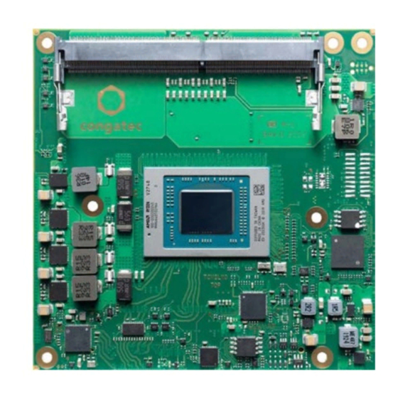
- Page 1 COM Express™ conga-TCV2 COM Express Type 6 Compact module based on AMD Ryzen Embedded V2000 SoC User’s Guide Revision 0.1 (Preliminary) Copyright © 2021 congatec GmbH TCV2m01 1/65...
- Page 2 Revision History Revision Date (yyyy-mm-dd) Author Changes 2021-11-22 • Preliminary release Copyright © 2021 congatec GmbH TCV2m01 2/65...
- Page 3 DECLINE ALL LIABILITY for damages, direct or indirect, that result from the use of this software. OEM/ CGUTL BIOS BIOS/UEFI modified by customer via the congatec System Utility (CGUTL) is subject to the same license as the BIOS/UEFI it is based on. You can find the specific details at https://www.congatec.com/en/licenses/.
- Page 4 The information contained within this user’s guide, including but not limited to any product specification, is subject to change without notice. congatec GmbH provides no warranty with regard to this user’s guide or any other information contained herein and hereby expressly disclaims any implied warranties of merchantability or fitness for any particular purpose with regard to any of the foregoing.
- Page 5 Copyright © 2021, congatec GmbH. All rights reserved. All text, pictures and graphics are protected by copyrights. No copying is permitted without written permission from congatec GmbH. congatec GmbH has made every attempt to ensure that the information in this document is accurate yet the information contained within is supplied “as-is”.
- Page 6 (c) arising from course of performance, course of dealing, or usage of trade. congatec GmbH shall in no event be liable to the end user for collateral or consequential damages of any kind. congatec shall not otherwise be liable for loss, damage or expense directly or indirectly arising from the use of the product or from any other cause.
- Page 7 GmbH technicians and engineers are committed to providing the best possible technical support for our customers so that our products can be easily used and implemented. We request that you first visit our website at www.congatec.com for the latest documentation, utilities and drivers, which have been made available to assist you.
-
Page 8: Table Of Contents
Feature List ................13 Additional Features ..............33 Supported Operating Systems ..........14 TPM ..................33 Mechanical Dimensions ............14 congatec Board Controller (cBC) ..........33 Supply Voltage Standard Power ..........15 6.2.1 Board Information ..............33 2.4.1 Electrical Characteristics ............15 6.2.2... - Page 9 BIOS Setup Description ............64 10.3 Updating the BIOS ..............65 10.4 Supported Flash Devices ............65 10.1 Navigating the BIOS Setup Menu ........... 64 10.2 BIOS Versions................64 Copyright © 2021 congatec GmbH TCV2m01 9/65...
- Page 10 Table 32 Thermal Protection Signal Descriptions ........60 Table 33 SMBus Signal Description ............60 Table 34 General Purpose Serial Interface Signal Descriptions ....60 Table 35 Module Type Definition Signal Description ......61 Copyright © 2021 congatec GmbH TCV2m01 10/65...
-
Page 11: Introduction
Simply unplug one module and replace it with another; no redesign is necessary. Copyright © 2021 congatec GmbH TCV2m01... -
Page 12: Options Information
Single or dual LVDS SoC TDP 45 W (35 W – 54 W) 45 W (35 W – 54 W) 15 W (10 W – 15 W) 15 W (10 W – 15 W) Copyright © 2021 congatec GmbH TCV2m01 12/65... -
Page 13: Specifications
2x UART (16C550 compatible) BIOS AMI Aptio V UEFI 2.x firmware ® 32 MB serial SPI flash with congatec Embedded BIOS features Power Management ACPI 5.0 compliant with battery support. S5e mode (see section 7.1.7 “Enhanced Soft-Off State”) Suspend to RAM (S3) -
Page 14: Supported Operating Systems
• Height of 11 mm (5 mm top-side, 2 mm PCB and 4 mm bottom-side) The overall height for heatspreader is shown below: Heatspreader Module PCB 4.00 13.00 7.00 5.00 or 8.00 2.00±10% All dimensions in millimeter 4.50 Carrier Board PCB Copyright © 2021 congatec GmbH TCV2m01 14/65... -
Page 15: Supply Voltage Standard Power
The input voltages shall rise from 10% of nominal to 90% of nominal at a minimum slope of 250V/s. The smooth turn-on requires that during the 10% to 90% portion of the rise time, the slope of the turn-on waveform must be positive. Copyright © 2021 congatec GmbH TCV2m01... -
Page 16: Power Consumption
Power Consumption The power consumption values were measured with the following setup: • conga-TCV2 module • modified congatec carrier board • conga-TCV2 cooling solution • Microsoft Windows 10 (64-bit) ® Note The SoC was stressed to its maximum workload with the AMD Validation Toolkit (AVT). -
Page 17: Supply Voltage Battery Power
3. Consider the self-discharge of the battery when calculating the lifetime of the CMOS battery. For more information, refer to application note AN9_RTC_Battery_Lifetime.pdf on congatec GmbH website at www.congatec.com/support/application-notes. 4. We recommend to always have a CMOS battery present when operating the conga-TCV2. -
Page 18: Environmental Specifications
Storage: 5% to 95% Caution The above operating temperatures must be strictly adhered to at all times. When using a congatec heatspreader, the maximum operating temperature refers to any measurable spot on the heatspreader’s surface. Humidity specifications are for non-condensing conditions. -
Page 19: Block Diagram
HD Audio SPI Flash 0 SPI0 SB-TSI MGMNT congatec SM Bus Board GPIOs GPIO Controller I2C Bus Generation LID/SLEEP/FAN LID# / SLEEP# / FAN UART 0-1 SER0/1 Optional - Not available by default Copyright © 2021 congatec GmbH TCV2m01 19/65... -
Page 20: Cooling Solutions
1. We recommend a maximum torque of 0.4 Nm for carrier board mounting screws and 0.5 Nm for module mounting screws. 2. The gap pad material used on congatec heatspreaders may contain silicon oil that can seep out over time depending on the environmental conditions it is subjected to. -
Page 21: Csa Dimensions
CSA Dimensions 38.65 25.5 A (2 : 1) 3.41 TYP M2.5 x 11 mm threaded standoff for threaded version ø2.7 x 11 mm non-threaded standoff for borehole version Copyright © 2021 congatec GmbH TCV2m01 21/65... -
Page 22: Csp Dimensions
CSP Dimensions 38.65 24.3 A (2 : 1) 3.41 TYP M2.5 x 11 mm threaded standoff for threaded version ø2.7 x 11 mm non-threaded standoff for borehole version Copyright © 2021 congatec GmbH TCV2m01 22/65... -
Page 23: Heatspreader Dimensions
Heatspreader Dimensions 38.65 M2.5 x 11 mm threaded standoff for threaded version ø2.7 x 11 mm non-threaded standoff for borehole version Copyright © 2021 congatec GmbH TCV2m01 23/65... -
Page 24: Connector Rows
The conga-TCV2 offers a x8 PEG port on the C–D connector. The default configuration of the PEG interface is 1 x8 link. The interface can be configured in the BIOS setup menu as a 2 x4 link. Note The PEG lanes can not be linked together with the PCI Express lanes in section 5.1.1 "PCI Express™". Copyright © 2021 congatec GmbH TCV2m01 24/65... -
Page 25: Display Interface
(assembly option). The LVDS interface supports: • single or dual channel LVDS (color depths of 18 bpp or 24 bpp) • integrated flat panel interface with clock frequency up to 112 MHz Copyright © 2021 congatec GmbH TCV2m01 25/65... -
Page 26: Sata
BIOS setup menu. The SATA interfaces support: • data transfer rates up to 6.0 Gb/s • AHCI mode Hot-plug detect Note The interfaces do not support legacy mode using I/O space. Copyright © 2021 congatec GmbH TCV2m01 26/65... -
Page 27: Usb
The USB ports are configured in the BIOS setup menu to operate by default in Gen 1 mode. Before you change the default setting to Gen 2, ensure the carrier board is designed for Gen 2 operation. For Gen 2 design considerations, contact congatec technical support center. -
Page 28: Lpc Bus
The SM bus is implemented through the congatec board controller and accessed through the congatec CGOS driver and API. 5.1.11 The SPI bus interface supports single and dual SPI interfaces with speeds up to 16 MHz. The conga-TCV2 discrete SPI TPM and the congatec BIOS flash are connected on the SPI interface. -
Page 29: Power Control
A sample screenshot is shown below: Note The module is kept in reset as long as the PWR_OK is driven by carrier board hardware. Copyright © 2021 congatec GmbH TCV2m01 29/65... - Page 30 0.8 V when the 12 V is applied to the module. Actively driving PWR_OK high is compliant to the COM Express specification but this can cause back driving. Therefore, congatec recommends driving the PWR_OK low to keep the module in reset and tri-state PWR_OK when the carrier board hardware is ready to boot.
- Page 31 This will help to determine if the rise is indeed monotonic and does not have any dips. For more information, see the “Power Supply Design Guide for Desktop Platform Form Factors” document at www.intel.com. Copyright © 2021 congatec GmbH TCV2m01...
-
Page 32: Power Management
(S3). For more information, see section 7.3 "ACPI Suspend Modes and Resume Events". S5e Power State The conga-TCV2 features a congatec proprietary Enhanced Soft-Off power state. See section 6.2.7 "Enhanced Soft-Off State" for more information. Copyright © 2021 congatec GmbH... -
Page 33: Additional Features
Board Controller (cBC) The conga-TCV2 is equipped with Microchip microcontroller. This onboard microcontroller plays an important role for most of the congatec embedded/industrial PC features. It fully isolates some of the embedded features such as system monitoring or the I²C bus from the x86 core architecture, which results in higher embedded feature performance and more reliability, even when the x86 processor is in a low power mode. -
Page 34: I 2 C Bus
OEM BIOS Customization The conga-TCV2 is equipped with congatec Embedded BIOS, which is based on American Megatrends Inc. Aptio UEFI firmware. The congatec Embedded BIOS allows system designers to modify the BIOS. For more information about customizing the congatec Embedded BIOS, refer to the congatec System Utility user’s guide CGUTLm1x.pdf on the congatec website at www.congatec.com or contact technical support. -
Page 35: Oem Default Settings
OEM POST Logo This feature allows system designers to replace the congatec POST logo displayed in the upper left corner of the screen during BIOS POST with their own BIOS POST logo. Use the congatec system utility CGUTIL 1.5.4 or later to replace/add the OEM POST logo. -
Page 36: Congatec Battery Management Interface
The architecture of the CGOS API driver provides the ability to write application software that runs unmodified on all congatec CPU modules. All the hardware related code is contained within the congatec embedded BIOS on the module. See section 1.1 of the CGOS API software developers guide, available on the congatec website. -
Page 37: Conga Tech Notes
• APIC extension for high core count system support • Cache-line Writeback (CLWB) • Processor register read at a user level • Quality of service monitoring • Improved prefetch throttling For more information about AMD Technology, visit http://www.amd.com. Copyright © 2021 congatec GmbH TCV2m01 37/65... -
Page 38: Thermal Management
If passive cooling is activated and the processor temperature is above the trip point the processor clock is throttled. See section 12 of the ACPI Specification 2.0 C for more information about passive cooling. Copyright © 2021 congatec GmbH TCV2m01... -
Page 39: Acpi Suspend Modes And Resume Events
In Device Manager look for the keyboard/mouse devices. Go to the Power Management tab and check ‘Allow this device to bring the computer out of standby’ RTC Alarm Activate and configure Resume On RTC Alarm in the Power setup menu. Only available in S5 Watchdog Power Button Event Wakes unconditionally from S3-S5 Copyright © 2021 congatec GmbH TCV2m01 39/65... -
Page 40: Signal Descriptions And Pinout Tables
The table below describes the terminology used in this section. The PU/PD column indicates if a pull-up or pull-down resistor has been used. If the field entry area in this column for the signal is empty, then no pull-up or pull-down resistor has been implemented by congatec. -
Page 41: A-B Connector Signal Descriptions
SATA3_RX+ GND (FIXED) GND (FIXED) SATA2_RX- SATA3_RX- eDP_TX3+ / LVDS_A_CK+ LVDS_B_CK+ BATLOW# eDP_TX3- / LVDS_A_CK- LVDS_B_CK- (S)ATA_ACT# HDA_SDIN2 eDP_ AUX+ / LVDS_I2C_CK eDP/LVDS_BKLT_CTRL HDA_SYNC HDA_SDIN1 eDP_AUX- / LVDS_I2C_DAT VCC_5V_SBY HDA_RST# HDA_SDIN0 GPI3 VCC_5V_SBY Copyright © 2021 congatec GmbH TCV2m01 41/65... - Page 42 B106 VCC_12V PCIE_TX5+ PCIE_RX5+ A107 VCC_12V B107 VCC_12V PCIE_TX5- PCIE_RX5- A108 VCC_12V B108 VCC_12V GPI0 GPO1 A109 VCC_12V B109 VCC_12V PCIE_TX4+ PCIE_RX4+ A110 GND (FIXED) B110 GND (FIXED) Note Not connected Not supported Copyright © 2021 congatec GmbH TCV2m01 42/65...
-
Page 43: Table 13 Connector C-D Pinout
PEG_TX8- DDI1_PAIR4+ RSVD GND (FIXED) GND (FIXED) DDI1_PAIR4- DDI1_PAIR0+ PEG_RX9+ PEG_TX9+ RSVD DDI1_PAIR0- PEG_RX9- PEG_TX9- RSVD RSVD RSVD RSVD DDI1_PAIR5+ DDI1_PAIR1+ DDI1_PAIR5- DDI1_PAIR1- PEG_RX10+ PEG_TX10+ GND (FIXED) GND (FIXED) PEG_RX10- PEG_TX10- DDI2_CTRLCLK_AUX+ DDI1_PAIR2+ Copyright © 2021 congatec GmbH TCV2m01 43/65... - Page 44 C107 VCC_12V D107 VCC_12V PEG_RX0- PEG_TX0- C108 VCC_12V D108 VCC_12V TYPE0# PEG_LANE_RV# C109 VCC_12V D109 VCC_12V PEG_RX1+ PEG_TX1+ C110 GND (FIXED) D110 GND (FIXED) Note Not connected Not supported congatec internal use only Copyright © 2021 congatec GmbH TCV2m01 44/65...
-
Page 45: Table 14 Pci Express Signal Descriptions (General Purpose)
O PCIE A PCI Express Gen3 compliant clock buffer chip must be used on PCIE_CLK_REF- and PCI Express Graphics Lanes the carrier board if the design involves more than one PCI Express device Copyright © 2021 congatec GmbH TCV2m01 45/65... -
Page 46: Table 15 Pci Express Signal Descriptions (X16 Graphics)
Note: Can also be used as PCI Express differential pairs 24 PEG_RX8- PEG_TX8+ O PCIE PEG_TX8- PEG_RX9+ PCI Express Graphics differential pairs 9 I PCIE Note: Can also be used as PCI Express differential pairs 25 PEG_RX9- PEG_TX9+ O PCIE PEG_TX9- Copyright © 2021 congatec GmbH TCV2m01 46/65... - Page 47 O PCIE PEG_TX15- D102 PEG_LANE_RV# D54 PCI Express Graphics lane reversal input strap. Pull low on the carrier board to Not supported reverse lane order. Note The conga-TCV2 supports only PEG ports 0-7. Copyright © 2021 congatec GmbH TCV2m01 47/65...
-
Page 48: Table 16 Ddi Signal Description
AUX pair is used for the DP AUX+/- signals. If pulled-high, the AUX pair contains the CTRLCLK and CTRLDATA signals. DDI3_PAIR0+ Multiplexed with DP3_LANE0+ and TMDS3_DATA2+ O DP Should be AC-coupled on the carrier DDI3_PAIR0- Multiplexed with DP3_LANE0- and TMDS3_DATA2- board. Copyright © 2021 congatec GmbH TCV2m01 48/65... -
Page 49: Table 17 Tmds Signal Descriptions
HDMI1_CTRLDATA TMDS I C Control Data I/OD 3.3 V PU 100 kΩ 2.2 kΩ to 3.3V pull-up should be implemented Multiplexed with DDI1_CTRLDATA_AUX- 3.3 V on the carrier board. Copyright © 2021 congatec GmbH TCV2m01 49/65... - Page 50 2.2 kΩ to 3.3V pull-up should be implemented Multiplexed with DDI3_CTRLDATA_AUX- 3.3 V on the carrier board. Note The conga-TCV2 does not natively support TMDS. For TMDS support, a DP++ to TMDS converter (e.g. PTN3360D) needs to be implemented.. Copyright © 2021 congatec GmbH TCV2m01 50/65...
-
Page 51: Table 18 Displayport Signal Descriptions
EDID access 3.3 V DP3_LANE3+ Uni-directional main link for the transport of isochronous streams and O DP Should be AC-coupled on the carrier board. DP3_LANE3- secondary data Multiplexed with DDI3_PAIR3+ and DDI3_PAIR3- Copyright © 2021 congatec GmbH TCV2m01 51/65... -
Page 52: Table 19 Embedded Displayport Signal Descriptions
Detection of hot plug / unplug and notification of the link layer I 3.3 V PD 100 kΩ Note The conga-TCV2 offers eDP interface as an assembly option. LVDS will not be supported if eDP is implemented. Copyright © 2021 congatec GmbH TCV2m01 52/65... -
Page 53: Table 20 Crt Signal Descriptions
DDC lines used for flat panel detection and control OD 3.3 V PU 2.2 kΩ 3.3 V LVDS_I2C_DAT DDC lines used for flat panel detection and control I/OD 3.3 V PU 2.2 kΩ 3.3 V Copyright © 2021 congatec GmbH TCV2m01 53/65... -
Page 54: Table 22 Sata Signal Descriptions
Differential USB 2.0 data pairs (backwards compatible to USB 1.1) I/O USB USB5- USB6+ Differential USB 2.0 data pairs (backwards compatible to USB 1.1) I/O USB USB6- USB7+ Differential USB 2.0 data pairs (backwards compatible to USB 1.1) I/O USB USB7- Copyright © 2021 congatec GmbH TCV2m01 54/65... - Page 55 Do not pull this line high on the carrier board. be present on the module. An open drain driver from a USB current 3.3 VSB monitor on the carrier board may drive this line low. Copyright © 2021 congatec GmbH TCV2m01 55/65...
-
Page 56: Table 24 Gigabit Ethernet Signal Descriptions
The GBE0_LINK# signal is a logic AND of the GBE0_LINK100# and GBE0_LINK1000# signals on the conga-TCV2 module. The LINK1000# output is active during 1 Gb and 2.5 Gb connection The ACT# output is active during LINK#, LINK100# and LINK1000# (all speed). The LEDs blink when an activity is detected. Copyright © 2021 congatec GmbH TCV2m01 56/65... -
Page 57: Table 25 High Definition Audio Link Signal Descriptions
Carrier shall pull to GND or left as no-connect. BIOS_DIS1# Selection strap to determine the BIOS boot device I 3.3 VSB PU 10 kΩ 3.3 VSB Carrier shall pull to GND or left as no-connect. Copyright © 2021 congatec GmbH TCV2m01 57/65... -
Page 58: Table 28 Miscellaneous Signal Descriptions
Active low, issued by module chipset and may result from a low SYS_RESET# input, a low PWR_OK input, a VCC_12V power input that falls below the minimum specification, a watchdog timeout, or may be initiated by the module software. Copyright © 2021 congatec GmbH TCV2m01 58/65... -
Page 59: Table 31 Rapid Shutdown Signal Descriptions
RAPID_SHUTDOWN Trigger for Rapid Shutdown. Must be driven to 5V though a <=50 ohm source I 3.3 V Not connected impedance for ≥ 20 μs Note The conga-TCV2 does not support Rapid Shutdown. Copyright © 2021 congatec GmbH TCV2m01 59/65... -
Page 60: Table 32 Thermal Protection Signal Descriptions
I 3.3 V PU 47 kΩ 3.3 V Note Pins are protected on the module by a series schotty diode. Therefore, pull-down resistor is required on the carrier board for proper logic level Copyright © 2021 congatec GmbH TCV2m01 60/65... -
Page 61: Table 35 Module Type Definition Signal Description
In R2.0 this pin is defined as a no-connect for Types 1-6. A carrier can detect a R1.0 module by the presence of 12 V on this pin. R2.0 module Types 1-6 will no-connect this pin. Type 10 modules shall pull this pin to ground through a 4.7 kΩ resistor. Copyright © 2021 congatec GmbH TCV2m01 61/65... -
Page 62: Bootstrap Signals
2. No external DC loads or external pull-up or pull-down resistors should change the configuration of the signals listed in the above table. External resistors may override the internal strap states and cause the COM Express™ module to malfunction and/or cause irreparable damage to the module. Copyright © 2021 congatec GmbH TCV2m01 62/65... -
Page 63: System Resources
System Resources Copyright © 2021 congatec GmbH TCV2m01 63/65... - Page 64 10.1 Navigating the BIOS Setup Menu The BIOS setup menu shows the features and options supported in the congatec BIOS. To access and navigate the BIOS setup menu, press the <DEL> or <F2> key during POST. The right frame displays the key legend. Above the key legend is an area reserved for text messages. These text messages explain the options and the possible impacts when changing the selected option in the left frame.
- Page 65 AMI AptioEFI firmware on an onboard flash ROM chip. You can update the firmware with the congatec System Utility. The utility has five versions— UEFI shell, DOS based command line , Win32 command line, Win32 GUI, and Linux version.
Need help?
Do you have a question about the COM Express conga-TCV2 and is the answer not in the manual?
Questions and answers