
Related Manuals for Congatec COM Express conga-TCA5


Summary of Contents for Congatec COM Express conga-TCA5
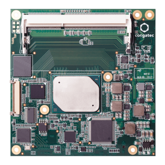
- Page 1 COM Express™ conga-TCA5 COM Express Type 6 Compact module based on the Intel Atom , Pentium and Celeron Apollo Lake SoC ® ™ ™ ® User's Guide Revision 1.9...
- Page 2 Combination” and table 17 “TMDS Signal Descriptions” • Updated section 3 “Block Diagram” and section 5.1.2 “Display Interfaces • Deleted section 5.1.2.1 “HDMI” and section 5.1.2.2 “DVI” • Added note to table 17 “TMDS Signal Descriptions” Copyright © 2017 congatec GmbH TA50m19 2/70...
- Page 3 Updated the note in section 5.1.2.3 "VGA" • Re-arranged section 6 "Additional Features" • Updated section 6.5 "congatec Battery Management Interface" 2021-11-16 • Deleted HDMI references from section 1.2 "Options Information", section 2.1 "Feature List", section 3 "Block Diagram and section 5.1.2 "Display Interfaces"...
- Page 4 DECLINE ALL LIABILITY for damages, direct or indirect, that result from the use of this software. OEM/ CGUTL BIOS BIOS/UEFI modified by customer via the congatec System Utility (CGUTL) is subject to the same license as the BIOS/UEFI it is based on. You can find the specific details at https://www.congatec.com/en/licenses/.
- Page 5 Copyright © 2017, congatec GmbH. All rights reserved. All text, pictures and graphics are protected by copyrights. No copying is permitted without written permission from congatec GmbH. congatec GmbH has made every attempt to ensure that the information in this document is accurate yet the information contained within is supplied “as-is”.
- Page 6 Trademarks Product names, logos, brands, and other trademarks featured or referred to within this user's guide, or the congatec website, are the property of their respective trademark holders. These trademark holders are not affiliated with congatec GmbH, our products, or our website.
- Page 7 (c) arising from course of performance, course of dealing, or usage of trade. congatec GmbH shall in no event be liable to the end user for collateral or consequential damages of any kind. congatec shall not otherwise be liable for loss, damage or expense directly or indirectly arising from the use of the product or from any other cause.
- Page 8 Serial ATA Display Data Channel System On Chip LVDS Low-Voltage Differential Signaling Gigabit Ethernet eMMC Embedded Multi-media Controller High Definition Audio congatec Board Controller Interface N.C. Not connected N.A. Not available To be determined Copyright © 2017 congatec GmbH TA50m19 8/70...
-
Page 9: Table Of Contents
Supported Operating Systems ..........16 Additional Features ..............34 Mechanical Dimensions ............16 Optional eMMC 5.0 ..............34 Supply Voltage Standard Power ..........17 congatec Board Controller (cBC) ..........34 2.4.1 Electrical Characteristics ............17 Board Information ..............34 2.4.2 Rise Time ................. - Page 10 9.1.1 LPC Bus ..................65 PCI Configuration Space Map ..........66 I²C Bus ..................67 SM Bus ..................67 congatec System Sensors ............68 BIOS Setup Description ............69 10.1 Navigating the BIOS Setup Menu ........... 69 10.2 BIOS Versions................69 10.3...
- Page 11 Table 33 Module Type Definition Signal Description ......63 Table 34 Power and GND Signal Descriptions ........64 Table 35 I/O Address Assignment ............65 Table 36 PCI Configuration Space Map ..........66 Copyright © 2017 congatec GmbH TA50m19 11/70...
-
Page 12: Introduction
This versatility allows the designer to create a dense and optimized package, which results in a more reliable product while simplifying system integration. Most importantly, COM Express™ Copyright © 2017 congatec GmbH TA50m19... -
Page 13: Options Information
1866 MT/s dual channel 1866 MT/s dual channel Single/dual 18/24 bpp Single/dual 18/24 bpp LVDS Optional VGA Default PCIe Lanes 3x PCIe lanes 3x PCIe lanes DP++ DP++ eMMC Optional Optional SD Card Max. TDP Copyright © 2017 congatec GmbH TA50m19 13/70... -
Page 14: Table 3 Industrial Variants
Single/dual 18/24 bpp Single/dual 18/24 bpp Optional VGA Default PCIe Lanes 3x PCIe lanes 3x PCIe lanes 3x PCIe lanes DP++ DP++ DP++ eMMC Optional Optional Optional SD Card Max. TDP 12 W 6.5 W Copyright © 2017 congatec GmbH TA50m19 14/70... -
Page 15: Specifications
C (fast mode, multi-master) BIOS AMI Aptio ® V UEFI 2.x firmware, 8 or 16 MB serial SPI with congatec Embedded BIOS features Storage Optional eMMC 5.0 onboard flash Power ACPI 4.0 compliant with battery support. Also supports Suspend to RAM (S3) and Intel AMT 10... -
Page 16: Supported Operating Systems
18 mm. If the 8 mm (height) carrier board connector is used then approximate overall height is 21 mm Heatspreader Module PCB 4.00 7.00 13.00 18.00 5.00 1.60 4.50 Carrier Board PCB Copyright © 2017 congatec GmbH TA50m19 16/70... -
Page 17: Supply Voltage Standard Power
The input voltages shall rise from 10% of nominal to 90% of nominal at a minimum slope of 250V/s. The smooth turn-on requires that during the 10% to 90% portion of the rise time, the slope of the turn-on waveform must be positive. Copyright © 2017 congatec GmbH TA50m19... -
Page 18: Power Consumption
Power Consumption The power consumption values were measured with the following setup: • Input voltage +12 V • conga-TCA5 COM • modified congatec carrier board • conga-TCA5 cooling solution • Microsoft Windows 10 (64 bit) Note The CPU was stressed to its maximum workload. -
Page 19: Supply Voltage Battery Power
3. Consider also the self-discharge of the battery when calculating the lifetime of the CMOS battery. For more information, refer to application note AN9_RTC_Battery_Lifetime.pdf on congatec GmbH website at www.congatec.com/support/application-notes. 4. We recommend to always have a CMOS battery present when operating the conga-TCA5. -
Page 20: Environmental Specifications
Storage: 5% to 95% Caution The above operating temperatures must be strictly adhered to at all times. When using a congatec heatspreader, the maximum operating temperature refers to any measurable spot on the heatspreader’s surface. Humidity specifications are for non-condensing conditions. -
Page 21: Block Diagram
Note: 3rd Gen congatec I2C Bus System Management Not available by default (assembly option) LID# / SLEEP# Controller LID# / SLEEP# Available only on product variant with PN: 048513 (Watchdog, EEProm...) FAN control Copyright © 2017 congatec GmbH TA50m19 21/70... -
Page 22: Cooling Solutions
1. We recommend a maximum torque of 0.4 Nm for carrier board mounting screws and 0.5 Nm for module mounting screws. 2. The gap pad material used on congatec heatspreaders may contain silicon oil that can seep out over time depending on the environmental conditions it is subjected to. -
Page 23: Csp Dimensions
4. Do not exceed the recommended maximum torque. Doing so may damage the module or the carrier board, or both. CSP Dimensions For Bare-die Variants 18.4 41.4 60° M2.5 x 8 mm threaded standoff for threaded version ø2.7 x 10 mm non-threaded standoff for borehole version Copyright © 2017 congatec GmbH TA50m19 23/70... - Page 24 For Lidded Variants 18.4 41.4 60° M2.5 x 8 mm threaded standoff for threaded version ø2.7 x 10 mm non-threaded standoff for borehole version Copyright © 2017 congatec GmbH TA50m19 24/70...
-
Page 25: Hsp Dimensions
HSP Dimensions For Bare-die Variants 18.4 41.4 60° M2.5 x 11 mm threaded standoff for threaded version ø2.7 x 11 mm non-threaded standoff for borehole version Copyright © 2017 congatec GmbH TA50m19 25/70... - Page 26 For Lidded Variants 18.4 41.4 60° M2.5 x 11 mm threaded standoff for threaded version ø2.7 x 11 mm non-threaded standoff for borehole version Copyright © 2017 congatec GmbH TA50m19 26/70...
-
Page 27: Connector Rows
• up to three independent displays (display combinations must be two DP++ and one LVDS/eDP) Note Requires a customized conga-TCA5 variant Assembly option combinations: 1 x DDI + 1 x eDP/LVDS + 1 x DDI/VGA Copyright © 2017 congatec GmbH TA50m19 27/70... -
Page 28: Displayport (Dp)
The conga-TCA5 offers an LVDS interface with optional eDP overlay on the A-B connector. The LVDS interface provides LVDS signals by default, but can optionally support eDP signals (assembly option). For more information, contact congatec technical center. The LVDS interface supports: •... -
Page 29: Vga
To pass the Electrical Fast Transient (EFT) test, you must add a schottky diode (1SS402 or equivalent) to all USB2.0 data lanes routed to a connector on your carrier board. The schottky diode must be placed before the common-mode choke as shown below. Copyright © 2017 congatec GmbH TA50m19... -
Page 30: Sata
Optionally, the UART ports can be routed from an LPC controller (Exar XR28V382) instead. Note The validated Intel HSUART driver, as well as the UART driver for the LPC controller is available on the congatec website at www.congatec.com. Copyright © 2017 congatec GmbH... -
Page 31: Expresscard
The conga-TCA5 offers a 4-bit SD interface for SD/MMC cards on the A-B connector. The SD signals are multiplexed with GPIO signals and controlled by the congatec Board controller. The SD card controller in the Storage Control Cluster of the SoC supports the SD interface with up to 832 Mbps data rate using 4 parallel data lines. -
Page 32: Power Control
A sample screenshot is shown below: Note The module is kept in reset as long as the PWR_OK is driven by carrier board hardware. Copyright © 2017 congatec GmbH TA50m19 32/70... -
Page 33: Power Management
Do this during the power supply qualification phase to ensure that the above mentioned problem does not occur in the application. For more information, see the “Power Supply Design Guide for Desktop Platform Form Factors” document at www.intel.com. 5.1.15 Power Management ACPI 5.0 compliant with battery support. Also supports Suspend to RAM (S3). Copyright © 2017 congatec GmbH TA50m19 33/70... -
Page 34: Additional Features
Board Controller (cBC) The conga-TCA5 is equipped with a microcontroller. This onboard microcontroller plays an important role for most of the congatec BIOS features. It fully isolates some of the embedded features such as system monitoring or the I²C bus from the x86 core architecture, which results in higher embedded feature performance and more reliability, even when the x86 processor is in a low power mode. -
Page 35: Fan Control
The conga-TCA5 is equipped with a multi stage watchdog solution that is triggered by software. The conga-TCA5 does not support external hardware triggering because the COM Express™ Specification does not provide support for external hardware triggering of the Watchdog. For more information, see the application note AN3_Watchdog.pdf on the congatec GmbH website at www.congatec.com. Note The conga-TCA5 module does not support the watchdog NMI mode. -
Page 36: Oem Bios Customization
OEM POST Logo This feature allows system designers to replace the congatec POST logo displayed in the upper left corner of the screen during BIOS POST with their own BIOS POST logo. Use the congatec system utility CGUTIL 1.5.4 or later to replace/add the OEM POST logo. -
Page 37: Oem Bios Code/Data
OEM BIOS Code/Data With the congatec embedded BIOS it is possible for system designers to add their own code to the BIOS POST process. The congatec Embedded BIOS first calls the OEM code before handing over control to the OS loader. -
Page 38: Api Support (Cgos)
The architecture of the CGOS API driver provides the ability to write application software that runs unmodified on all congatec CPU modules. All the hardware related code is contained within the congatec embedded BIOS on the module. See section 1.1 of the CGOS API software developers guide, which is available on the congatec website. -
Page 39: Conga Tech Notes
Intel VT-x) added hardware support in the processor to improve the virtualization performance and robustness. ® RTS Real-Time Hypervisor supports Intel VT and is verified on all current congatec x86 hardware. Note congatec supports RTS Hypervisor. Copyright © 2017 congatec GmbH... -
Page 40: Thermal Management
If passive cooling is activated and the processor temperature is above the trip point the processor clock is throttled. See section 12 of the ACPI Specification 2.0 C for more information about passive cooling. Copyright © 2017 congatec GmbH TA50m19... -
Page 41: Acpi Suspend Modes And Resume Events
In Device Manager look for the keyboard/mouse devices. Go to the Power Management tab and check ‘Allow this device to bring the computer out of standby’. RTC Alarm Activate and configure Resume On RTC Alarm in the Power setup menu. Only available in S5. Watchdog Power Button Event Wakes unconditionally from S3-S5. Copyright © 2017 congatec GmbH TA50m19 41/70... -
Page 42: Usb Port Mapping
USB 2.0 USB 2.0 USB 2.0 Port 7 Port 0 Port 1 Port 2 Port 4 Port 5 Port 6 Port 3 Port 0 Port 1 Port 2 Port 3 COM Express Connector Copyright © 2017 congatec GmbH TA50m19 42/70... -
Page 43: Signal Descriptions And Pinout Tables
Signal Descriptions and Pinout Tables The following section describes the signals found on COM Express™ Type 6 connectors used for congatec GmbH modules. The pinout of the modules complies with COM Express Type 6 Rev. 2.1. The table below describes the terminology used in this section. The PU/PD column indicates if a COM Express™ module pull-up or pull-down resistor has been used. -
Page 44: Connector Signal Descriptions
GND (FIXED) LVDS_A2- LVDS_B2- SATA2_TX+ * SATA3_TX+ * LVDS_VDD_EN LVDS_B3+ SATA2_TX- * SATA3_TX- * LVDS_A3+ LVDS_B3- SUS_S5# PWR_OK LVDS_A3- LVDS_BKLT_EN SATA2_RX+ * SATA3_RX+ * GND (FIXED) GND (FIXED) SATA2_RX- * SATA3_RX- * LVDS_A_CK+ LVDS_B_CK+ Copyright © 2017 congatec GmbH TA50m19 44/70... - Page 45 PCIE_TX5- * PCIE_RX5- * A108 VCC_12V B108 VCC_12V GPI0 GPO1 A109 VCC_12V B109 VCC_12V PCIE_TX4+ PCIE_RX4+ A110 GND (FIXED) B110 GND (FIXED) Note Not supported on conga-TCA5 Supported via an assembly option (customized variant) Copyright © 2017 congatec GmbH TA50m19 45/70...
-
Page 46: Table 13 Connector C-D Pinout
PEG_RX9+ * PEG_TX9+ * RSVD DDI1_PAIR0- PEG_RX9- * PEG_TX9- * RSVD RSVD RSVD RSVD DDI1_PAIR5+ * DDI1_PAIR1+ DDI1_PAIR5- * DDI1_PAIR1- PEG_RX10+ * PEG_TX10+ * GND (FIXED) GND (FIXED) PEG_RX10- * PEG_TX10- * DDI2_CTRLCLK_AUX+ DDI1_PAIR2+ Copyright © 2017 congatec GmbH TA50m19 46/70... - Page 47 VCC_12V PEG_RX0- * PEG_TX0- * C108 VCC_12V D108 VCC_12V TYPE0# * PEG_LANE_RV# * C109 VCC_12V D109 VCC_12V PEG_RX1+ * PEG_TX1+ * C110 GND (FIXED) D110 GND (FIXED) Note Not supported on the conga-TCA5 Copyright © 2017 congatec GmbH TA50m19 47/70...
-
Page 48: Table 14 Pci Express Signal Descriptions (General Purpose)
PCI Express Reference Clock output for all PCI Express O PCIE A PCI Express compliant clock buffer chip must be PCIE_CLK_REF- and PCI Express Graphics Lanes. used on the carrier board if more than one PCI Express device is designed in. Copyright © 2017 congatec GmbH TA50m19 48/70... -
Page 49: Table 15 Pci Express Signal Descriptions (X16 Graphics)
PCIE_RX[16-31] + and -. PEG_RX1+ PEG_RX1- PEG_RX2+ PEG_RX2- PEG_RX3+ PEG_RX3- PEG_RX4+ PEG_RX4- PEG_RX5+ PEG_RX5- PEG_RX6+ PEG_RX6- PEG_RX7+ PEG_RX7- PEG_RX8+ PEG_RX8- PEG_RX9+ PEG_RX9- PEG_RX10+ PEG_RX10- PEG_RX11+ PEG_RX11- PEG_RX12+ PEG_RX12- PEG_RX13+ PEG_RX13- PEG_RX14+ PEG_RX14- PEG_RX15+ C101 PEG_RX15- C102 Copyright © 2017 congatec GmbH TA50m19 49/70... - Page 50 D101 PEG_TX15- D102 PEG_LANE_RV# PCI Express Graphics lane reversal input strap. Pull low on the carrier board to reverse lane Not supported. order. Note PCI Express Graphics is not supported on conga-TCA5 modules Copyright © 2017 congatec GmbH TA50m19 50/70...
-
Page 51: Table 16 Ddi Signal Description
Multiplexed with DP2_LANE2+ and TMDS2_DATA0+. O PCIE DDI2_PAIR2- Multiplexed with DP2_LANE2- and TMDS2_DATA0-. DDI2_PAIR3+ Multiplexed with DP2_LANE3+ and TMDS2_CLK+. O PCIE DDI2_PAIR3- Multiplexed with DP2_LANE3- and TMDS2_CLK-. DDI2_HPD Multiplexed with DP2_HPD and HDMI2_HPD. I 3.3V PD 100k Copyright © 2017 congatec GmbH TA50m19 51/70... - Page 52 AUX-. This pin shall have a IM pull-down to logic ground on the module. If this input is floating, the AUX pair is used for the DP AUX+/- signals. If pulled-high, the AUX pair contains the CTRLCLK and CTRLDATA signals Copyright © 2017 congatec GmbH TA50m19 52/70...
-
Page 53: Table 17 Tmds Signal Descriptions
Multiplexed with DDI3_PAIR2+ and DDI3_PAIR2-. TMDS3_DATA1+ TMDS differential pair. O PCIE Not supported TMDS3_DATA1- Multiplexed with DDI3_PAIR1+ and DDI3_PAIR1-.. TMDS3_DATA2+ TMDS differential pair. O PCIE Not supported TMDS3_DATA2- Multiplexed with DDI3_PAIR0+ and DDI3_PAIR0-. Copyright © 2017 congatec GmbH TA50m19 53/70... -
Page 54: Table 18 Displayport (Dp) Signal Descriptions
Uni-directional main link for the transport of isochronous streams and secondary data. O PCIE DP2_LANE0- Multiplexed with DDI2_PAIR0+ and DDI1_PAIR0- DP2_HPD Detection of Hot Plug / Unplug and notification of the link layer. I 3.3V PD 100k Multiplexed with DDI2_HPD. Copyright © 2017 congatec GmbH TA50m19 54/70... -
Page 55: Table 19 Crt Signal Descriptions
O 3.3V VGA_I2C_CK DDC clock line (I²C port dedicated to identify VGA monitor capabilities) I/O OD 5V VGA_I2C_DAT B96 DDC data line. I/O OD 5V Note The optional VGA interface requires a customized variant. Copyright © 2017 congatec GmbH TA50m19 55/70... -
Page 56: Table 20 Lvds Signal Descriptions
O SATA Supports Serial ATA 3 specification, up to 6 Gbps SATA0_TX- SATA1_RX+ Serial ATA channel 1, Receive Input differential pair. I SATA Supports Serial ATA 3 specification, up to 6 Gbps SATA1_RX- Copyright © 2017 congatec GmbH TA50m19 56/70... -
Page 57: Table 22 Usb 2.0 Signal Descriptions
Do not pull this line high on the carrier board. shall be present on the module. An open drain driver from a USB 3.3VSB current monitor on the carrier board may drive this line low. Copyright © 2017 congatec GmbH TA50m19 57/70... -
Page 58: Table 23 Usb 3.0 Signal Descriptions
Additional transmit signal differential pairs for the Superspeed USB data path USB_SSTX2- USB_SSRX3+ Additional receive signal differential pairs for the Superspeed USB data path I USB_SSRX3- USB_SSTX3+ Additional transmit signal differential pairs for the Superspeed USB data path USB_SSTX3- Copyright © 2017 congatec GmbH TA50m19 58/70... -
Page 59: Table 24 Gigabit Ethernet Signal Descriptions
2k2 PD AC'97 codecs are not supported. from the codec(s). This serial input is single-pumped for a bit rate of 24 Mbps for AC/HDA_SDIN[2:1] signals are Intel High Definition Audio. not supported. ® Copyright © 2017 congatec GmbH TA50m19 59/70... -
Page 60: Table 26 Expresscard Support Pins Descriptions
I 3.3VSB PU 10k Carrier shall pull to GND or leave no-connect. 3.3VSB BIOS_DIS1# Selection strap to determine the BIOS boot device. I 3.3VSB PU 10k Carrier shall pull to GND or leave no-connect. 3.3VSB Copyright © 2017 congatec GmbH TA50m19 60/70... -
Page 61: Table 29 Miscellaneous Signal Descriptions
General purpose input pins. Pulled high internally on the module. I 3.3V PU 10K Pull-up only active in GPIO mode Shared with SD_DATA3. Bidirectional signal. 3.3V Table 31 Power and System Management Signal Descriptions Copyright © 2017 congatec GmbH TA50m19 61/70... - Page 62 Sleep button. Used by the ACPI operating system to bring the system to sleep state or to wake it I OD 3.3V PU 100k up again. 3.3VSB Note: For proper detection, assert a pulse width of at least 16 ms. Copyright © 2017 congatec GmbH TA50m19 62/70...
-
Page 63: Table 32 General Purpose Serial Interface Signal Descriptions
Types 1-6. A carrier can detect a R1.0 module by the presence of 12V on this pin. R2.0 module Types 1-6 will no-connect this pin. Type 10 modules shall pull this pin to ground through a 4.7k resistor. Copyright © 2017 congatec GmbH TA50m19... -
Page 64: Table 34 Power And Gnd Signal Descriptions
C76, C80, C84, C87, C90, C93, C96, C100, C103, C110, D1, D2, D5, D8, D11, D14, D21, D31, D41, D51, D60, D67, D70, D73, D76, D80, D84, D87, D90, D93, D96, D100, D103, D110 Copyright © 2017 congatec GmbH TA50m19 64/70... -
Page 65: System Resources
PCI bus (only specified I/O ranges are forwarded to the LPC bus). With the default settings in the congatec Embedded BIOS, the following I/O address ranges are forwarded to the LPC bus: 80h - 8Fh (via LPC Generic I/O Range 1) A00h - A1Fh (via LPC Generic I/O Range 4) Copyright ©... -
Page 66: Pci Configuration Space Map
Parts of these ranges are not available if a Super I/O is used on the carrier board. If a Super I/O is not implemented on the carrier board, then all these ranges are available for customer use. If you require additional LPC Bus resources other than those mentioned above, or more information about this subject, contact congatec technical support for assistance. PCI Configuration Space Map... -
Page 67: I²C Bus
Disabled by default in the BIOS Setup menu. I²C Bus No onboard resource is connected to the I²C bus. Address 16h is reserved for congatec Battery Management solutions. SM Bus The System Management (SM) bus signals are connected to the Intel Apollo Lake SoC and is not intended to be used by off-board non-system management devices. -
Page 68: Congatec System Sensors
– 5V standard voltage sensor – 5V standby voltage sensor • current sensor • fan monitor The sensors and monitors are accessible through CGOS interface, and also visible on the "Health Monitor"submenu in the BIOS Setup: Copyright © 2017 congatec GmbH TA50m19 68/70... -
Page 69: Bios Setup Description
Navigating the BIOS Setup Menu The BIOS setup menu shows the features and options supported in the congatec BIOS. To access and navigate the BIOS setup menu, press the <DEL> or <F2> key during POST. The right frame displays the key legend. Above the key legend is an area reserved for text messages. These text messages explain the options and the possible impacts when changing the selected option in the left frame. -
Page 70: Updating The Bios
AMI AptioEFI firmware on an onboard flash ROM chip. You can update the firmware with the congatec System Utility. The utility has five versions— UEFI shell, DOS based command line , Win32 command line, Win32 GUI, and Linux version.
Need help?
Do you have a question about the COM Express conga-TCA5 and is the answer not in the manual?
Questions and answers