
Subscribe to Our Youtube Channel
Related Manuals for ADLINK Technology LEC-BTS


Summary of Contents for ADLINK Technology LEC-BTS
- Page 1 LEC-BTS Technical Reference Low Energy Computer On Module with Intel® Atom™ E3800 Series and N2807 Celeron® Processors Manual Rev.: Revision Date: May 3, 2018 Part Number: 50-1Z173-1020 Leading EDGE COMPUTING...
-
Page 2: Preface
Audience This manual provides reference only for computer design engineers, including but not limited to hardware and software designers and applications engineers. ADLINK Technology, Inc. assumes you are qualified to design and implement prototype computer equipment. Preface... - Page 3 LEC-BTS Environmental Responsibility ADLINK is committed to fulfill its social responsibility to global environmen- tal preservation through compliance with the European Union's Restriction of Hazardous Substances (RoHS) directive and Waste Electrical and Elec- tronic Equipment (WEEE) directive. Environmental protection is a top prior- ity for ADLINK.
- Page 4 Important Safety Instructions For user safety, please read and follow all Instructions, WARNINGs, CAUTIONs, and NOTEs marked in this manual and on the associated equipment before handling/operating the equipment. Read these safety instructions carefully. Keep this manual for future reference. ...
-
Page 5: Table Of Contents
LEC-BTS Table of Contents Preface ..........................ii 1 Overview ......................... 1 Block Diagram ........................1 Major Components (ICs) ......................2 Connectors, Switches, and LEDs ..................3 Specifications ......................... 6 1.4.1 Physical Specifications ....................6 1.4.2 Mechanical Specifications .....................6 1.4.3 Electrical Specifications ....................7 1.4.4... - Page 6 4 Utilities ........................... 23 BIOS ........................... 23 4.1.1 Starting the BIOS Setup Utility ..................23 4.1.2 Main Menu ........................24 4.1.3 Advanced Menu ......................29 4.1.4 Security Menu ......................54 4.1.5 Boot ..........................55 4.1.6 Save & Exit ........................58 SEMA functions ........................
-
Page 7: Overview
LEC-BTS Overview This manual presents a general overview of the LEC-BTS. After reviewing this document you should understand the following perspectives of the LEC-BTS. Feature Overview Hardware Functions Interface Signal Definitions Utility Definitions Contact Information ... -
Page 8: Major Components (Ics)
Major Components (ICs) Table 1-1 lists the major integrated circuits on the LEC-BTS, including a brief description of each IC. Figures 1-2 and 1-3 show the locations of the major ICs. Table 1-1: Major Integrated Circuit Descriptions and Functions Chip Type Mfg. -
Page 9: Connectors, Switches, And Leds
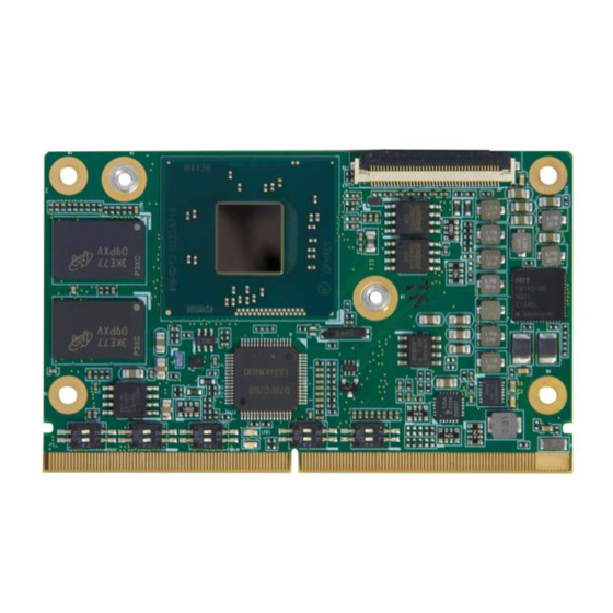
LEC-BTS Key: - GbE Controller - DDR3L SDRAM - DDR3L SDRAM S158 Figure 1-3: Component Locations (Bottom Side) Connectors, Switches, and LEDs Table 1-2 describes the connectors, switches, and LEDs shown in Figure 1-4. Table 1-2: Module Connector Description Board... - Page 10 Table 1-2: Module Connector Description (Continued) Board Reference Description Access SW1, SW2, SW3 Configurations: • Camera with 1 MIPI-CSI lane = SW1-SW3 switches all set to ON • Camera with 2 MIPI-CSI lanes = SW1 (both OFF); SW2 (both ON); SW3 (both ON) •...
- Page 11 LEC-BTS Key: - DB40 Bebug - SMARC LED1 - System Status LED2 - Power ON - CSI 1 Camera - CSI 2 Camera - CSI 3 Camera - BIOS Defaults - BIOS1-2 Select LED1 LED2 P156 GF1B GF1A Figure 1-4: Connector Locations (Top Side)
-
Page 12: Specifications
Specifications 1.4.1 Physical Specifications Table 1-3 lists the physical dimensions of the module. Table 1-3: Weight and Footprint Dimensions Overall height is measured from the upper board Item Dimension surface to the top of the highest permanent Weight 0.02 kg (0.05 lb) component (CN1 connector) on the upper board Height (overall) 2.50 mm (0.098 inches) -
Page 13: Electrical Specifications
LEC-BTS 1.4.3 Electrical Specifications Table 1-4 specifies the electrical characteristics of the module. Table 1-4: Electrical Specifications Parameter Value Voltage Input Standard Fixed 5-Volt Supply (+4.75V DC min to +5.25V DC max) 3.0V, 2.0V to 3.3V (battery) Power States C1-C6 processor power states ... -
Page 14: Thermal/Cooling Requirements
1.4.6 Thermal/Cooling Requirements The LEC-BTS is designed to operate at its maximum CPU speeds and requires a thermal solu- tion to cool the SoC. ADLINK offers a heat spreader (separate order number) for cooling. This facilitates future module upgrades without the need to re-design the custom heatsink. -
Page 15: Hardware
DDR3L memory (92) Thermal Sensor LM73 Getting Started Mount the LEC-BTS to the carrier as illustrated in Figure 2-1, which provides a profile view of the module mounted to the carrier with dimensions. Figure 2-1: SMARC module mounting dimensions (profile) Hardware... - Page 16 If you need to load the BIOS default values, they can be automatically loaded at boot time. The LEC-BTS boots from CD drives, USB sticks, hard disks, or µSD-Cards. Provided that any of these is connected and contains a valid operating system image, the display then shows the boot screen of your operating system.
-
Page 17: Interfaces
The main chips used in the LEC-BTS may provide more features or options than are listed for the LEC-BTS, but some of these features or options are not supported on the mod- ule and will not function as specified in the chip docu- mentation. -
Page 18: Hdmi (High-Definition Multimedia Interface)
PCI Express (PCIe) The CPU features four PCIe x1 ports, and the LEC-BTS module uses three of them for the PCIe interface and one of them for the Gigabit Ethernet interface. The PCIe interface supports the PCIe Base Specification 2.0 with a maximum signal rate of 5 GT/s and can be configured to sup- port PCIe edge cards or Express Cards. -
Page 19: I2C Bus
SDMMC pins on the SMARC connector. 3.15 GPIO The LEC-BTS provides 12 GPIO signals from the CMOS device on the module. The GPIO sig- nals can be utilized for General Purpose IOs as well as camera, HDA, PWM, TACH, and CAN interfaces. -
Page 20: Smarc Interface Signals
3.17 SMARC Interface Signals Table 3-2 provides the pin signals for the SMARC P-S connector. Refer to the SMARC specifica- tion at http://www.sget.org/standards/smarc.html for definitions of the SMARC signals. Table 3-2: SMARC P-S Connector (GF1) Signal Descriptions Pin # Primary (Top Side) Pin # Secondary (Bottom Side) Not connected... - Page 21 LEC-BTS Table 3-2: SMARC P-S Connector (GF1) Signal Descriptions (Continued) Pin # Primary (Top Side) Pin # Secondary (Bottom Side) GBE_LINK_ACT# (Link / Activity SDMMC_D0 (bidirectional, 8-bit data path; Indication LED Driven low on Link [10, may be used for 4- and 1-bit wide eMMC 100 or 1000 mbps] Blinks on Activity;...
- Page 22 Table 3-2: SMARC P-S Connector (GF1) Signal Descriptions (Continued) Pin # Primary (Top Side) Pin # Secondary (Bottom Side) SATA0_TX- (Differential SATA 0 transmit I2S2_LRCK (Left & Right audio data Pair; 0.1 uF 0402 capacitor on synchronization clock) module) I2S2_SDOUT (Digital audio output) SATA0_RX+ (Differential SATA 0 receive I2S2_SDIN (Digital audio input) data Pair;...
- Page 23 LEC-BTS Table 3-2: SMARC P-S Connector (GF1) Signal Descriptions (Continued) Pin # Primary (Top Side) Pin # Secondary (Bottom Side) USB2+ (Differential USB2 data pair) USB2- (Differential USB2 data pair) AFB_DIFF3+ (maps to SATA_TX1_P on the SOC) USB2_EN_OC# (Pulled low by Module AFB_DIFF3- (maps to SATA_TX1_N on the OD driver to disable USB2 power.
- Page 24 Table 3-2: SMARC P-S Connector (GF1) Signal Descriptions (Continued) Pin # Primary (Top Side) Pin # Secondary (Bottom Side) PCIE_A_TX+ (Differential PCIe Link A PCIE_B_TX+ (Differential PCIe Link B transmit data pair 0. Series coupling transmit data pair 0. Series coupling caps capacitors are on the Module.
- Page 25 LEC-BTS Table 3-2: SMARC P-S Connector (GF1) Signal Descriptions (Continued) Pin # Primary (Top Side) Pin # Secondary (Bottom Side) P117 GPIO9 (General Purpose IO) S118 Not connected P118 GPIO10 (General Purpose IO) S119 P119 GPIO11 (General Purpose IO) S120...
- Page 26 Table 3-2: SMARC P-S Connector (GF1) Signal Descriptions (Continued) Pin # Primary (Top Side) Pin # Secondary (Bottom Side) P140 Not connected S141 LCD_BKLT_PWM (Display backlight PWM control) P141 Not connected S142 Not connected P142 S143 P143 Not connected S144 RSVD / EDP_HPD (Reserved for future eDP Hot Plug Detect pin) P144...
- Page 27 LEC-BTS Table 3-2: SMARC P-S Connector (GF1) Signal Descriptions (Continued) Pin # Primary (Top Side) Pin # Secondary (Bottom Side) P153 VDD_IN (Module power input voltage - S154 CARRIER_PWR_ON (Carrier board circuits [apart from power management and power path circuits] are powered up until the...
-
Page 28: Debug (Db40)
3.18 Debug (DB40) Table 3-3 lists the pin signals of the CN1 connector, which provides 40 pins, 1 row, consecutive sequence with 0.02" (0.50mm) pitch. Table 3-3: Debug Interface Signals (CN1) Pin # Interface Signal RESVD (0R0 PD to GND) SMC_STATUS (Connect LED) SMC Debug BIOS_MODE (Not Used) -
Page 29: Utilities
LEC-BTS. BIOS The LEC-BTS features an AMI BIOS. The default settings provide a “ready to run” system, even without a BIOS setup backup battery. The BIOS is located in flash memory and can be easily updated with software under DOS. -
Page 30: Main Menu
4.1.2 Main Menu The Main Menu provides read-only information about your system and also allows you to change System Management settings and set the System Date and Time. Refer to the tables below for details of the submenus and settings. Figure 4-1: BIOS Setup Main Menu BIOS Information Table 4-2: Main Menu BIOS Information... - Page 31 LEC-BTS Memory Information Table 4-4: Main Menu Memory Information Feature Options Description Total Memory Info only Display total memory information GOP Information Table 4-5: Main Menu GOP Information Feature Options Description Intel(R) GOP Driver I[N/A] TXE Information Table 4-6: Main Menu TXE Information...
- Page 32 Main Menu > System Management > Temperatures Table 4-8: Main Menu > System Management > Temperature Feature Options Description Temperatures Info only Board Temperatures Info only Current Read only Display current board temperature Startup Read only Display board startup temperature ...
- Page 33 LEC-BTS Main Menu > System Management > Runtime Statistics Table 4-10: Main Menu > System Management > Runtime Statistics Feature Options Description Runtime Statistics Info only Total Runtime Read only The returned value specifies the total time in minutes the system is running in S0 state.
- Page 34 Main Menu > System Management > LVDS Backlight Table 4-13: Main Menu > System Management > LVDS Backlight Feature Options Description LVDS Backlight Info only LVDS Backlight Bright The value range starts at 0 and ends at 255. Main Menu > System Date and Time Table 4-14: Main Menu >...
-
Page 35: Advanced Menu
LEC-BTS 4.1.3 Advanced Menu This menu contains the settings for most of the user interfaces in the system. The “Advanced” menu provides configuration settings for CPU, Memory, Graphics, SATA, USB, SDIO, Network, Audio, PCIe Configuration, ACPI, Serial Console, Thermal, Security, and Miscellaneous. - Page 36 Advanced Menu > CPU Configuration Figure 4-3: BIOS Setup Advanced Menu > CPU Configuration Utilities...
- Page 37 LEC-BTS Advanced > CPU Configuration > Socket 0 CPU Information Table 4-15: Advanced > CPU Configuration > Socket 0 Information Feature Options Description CPU Brand Name Info only Display CPU brand name CPU Signature Info only Display CPU signature Microcode Patch...
- Page 38 Advanced > CPU Configuration > PPM Configuration Table 4-17: Advanced > CPU Configuration > CPU Thermal Configuration Feature Options Description CPU C state report • Disabled Enable/Disable CPU C state report to OS • Enabled Max CPU C state This option controls Max C state that the •...
- Page 39 LEC-BTS Advanced Menu > Graphics Figure 4-4: BIOS Setup Advanced Menu > Graphics Configuration Utilities...
- Page 40 Advanced > Graphics > Intel IGD Configuration Table 4-18: Advanced > Graphics Configuration Feature Options Description Integrated Graphics Device • Enabled Enabled: Enable Integrated Graphics • Disabled Device (IGD) when selected as the primary display; Disabled: Always disable IGD IGD Turbo Enable •...
- Page 41 LEC-BTS Advanced > Graphics > VBIOS - LCD Control Table 4-20: Advanced > Graphics > VBIOS > LCD control Feature Options Description Primary IGFX Boot Display • VBIOS Default Select the Video Device that will be activated • HDMI during POST. This has no effect if external •...
- Page 42 Table 4-22: Advanced > SATA Feature Options Description Serial-ATA Controller • Enabled Enable/Disable Serial ATA. • Disabled SATA Test Mode • Enabled Test Mode enable/disable • Disabled SATA Speed Support • Gen1 SATA speed support Gen1 or Gen2. • Gen2 SATA ODD Port •...
- Page 43 LEC-BTS Table 4-23: Advanced Menu > USB Feature Options Description Info only USB Module Version Info only USB Devices Info only Drives, keyboards, mouse, hubs Legacy USB Support • Enabled • Enables legacy USB support. • Disabled • Auto option disables legacy support if no USB •...
- Page 44 Advanced > USB > USB Host Controller Configuration Table 4-24: Advanced Chipset USB Configuration Feature Options Description USB Client Support • PCI mode Enable/Disable USB OTG Support • Disabled XHCI Mode • Enabled Mode of operation of xHCI controller. • Disabled •...
- Page 45 LEC-BTS Table 4-25: Advanced Menu > SDIO Feature Options Description SDIO Access Mode • Auto Auto Option: Access SD device in DMA • DMA mode if controller supports it, other wise • PIO in PIO mode. DMA Option: Access SD device in DMA mode.
- Page 46 Advanced Menu > Audio Configuration Figure 4-9: BIOS Setup Advanced Menu > Audio Configuration Table 4-27: Advanced Menu > Audio Configuration Feature Options Description LPE Audio Support • Enabled Select LPE Audio ACPI mode or PCI mode • Disabled Audio Controller •...
- Page 47 LEC-BTS Advanced Menu > PCI_PCIe Configuration Figure 4-10: BIOS Setup Advanced Menu > PCI_PCIe Configuration Advanced Menu > PCIe Configuration > PCIe Chipset Settings Table 4-28: Advanced Menu > PCIe Configuration > PCIe Chipset Settings Feature Options Description PCI Express Port x •...
- Page 48 Advanced Menu > PCIe Configuration > PCI Subsystem Settings Table 4-29: Advanced Menu > PCIe Configuration > PCI Subsystem Settings Feature Options Description PCI Latency Timer Value to be programmed into PCI 32 PCI Bus Clocks latency timer register PCI-X Latency Timer Value to be programmed into PCI-X 64 PCI Bus Clocks latency timer register...
- Page 49 LEC-BTS Advanced Menu > PCIe Configuration > PCI Subsystem Settings > PCI Express Settings Table 4-30: Advanced Menu > PCIe Configuration > PCI Subsystem Settings > PCIe Settings Feature Options Description Relaxed Ordering • Enabled Enables or Disables PCI Express device relaxed ordering.
- Page 50 Advanced Menu > PCIe Configuration > PCI Subsystem Settings > PCI Express GEN 2 Settings Table 4-31: Advanced Menu > PCIe Configuration > PCI Subsystem Settings > PCIe GEN 2 Settings Feature Options Description Completion Timeout • Default In device Functions that support •...
- Page 51 LEC-BTS Table 4-31: Advanced Menu > PCIe Configuration > PCI Subsystem Settings > PCIe GEN 2 Settings (Continued) Feature Options Description Target Link Speed • Auto If supported by hardware and set to • Force to 2.5 GT/s 'Force to 2.5 GT/s' for Downstream •...
- Page 52 Advanced Menu > Baytrail Features Figure 4-11: BIOS Setup Advanced Menu > Baytrail Features Table 4-32: Advanced > Baytrail Features Feature Options Description LPSS & SCC Devices Mode • ACPI mode LPSS & SCC Devices Mode Settings • PCI mode SCC Configuration Info only SCC eMMC Support...
- Page 53 LEC-BTS Table 4-32: Advanced > Baytrail Features (Continued) Feature Options Description LPSS HSUART #1 Support • Enabled LPSS HSUART #1 Support • Disabled Enable\Disable LPSS HSUART #2 Support • Enabled LPSS HSUART #2 Support • Disabled Enable\Disable LPSS SPISupport • Enabled LPSS SPISupport Enable\Disable •...
- Page 54 Table 4-33: Advanced > ACPI Feature Options Description Lock Legacy Resources • Enabled Enables or Disables Lock of Legacy Resources • Disabled Advanced Menu > Serial Port Console Redirection Figure 4-13: BIOS Setup Advanced Menu > Serial Port Console Redirection Table 4-34: Advanced Menu >...
- Page 55 LEC-BTS Advanced Menu > Serial Port Console Redirection > Console Redirection Settings Table 4-35: Advanced Menu > Serial Port Console Redirection > Console Redirection Settings Feature Options Description • COM0/COM1 Info only • Console Redirection Settings Terminal Type • VT100 VT100: ASCII char set.
- Page 56 Advanced Menu > Thermal Figure 4-14: BIOS Setup Advanced Menu > Thermal Table 4-36: Advanced Menu > Thermal Feature Options Description Critical Trip Point • Disabled This value controls the temperature of • 85 C the ACPI critical Trip Point - the point •...
- Page 57 LEC-BTS Advanced Menu > Security Figure 4-15: BIOS Setup Advanced Menu > Security Table 4-37: Advanced Menu > Security Feature Options Description • Enabled • Disabled TXE HMRFPO • Enabled • Disabled TXE Firmware Update • Enabled • Disabled TXE EOP Message •...
- Page 58 Advanced Menu > Miscellaneous Figure 4-16: BIOS Setup Advanced Menu > Miscellaneous Table 4-38: Advanced > Miscellaneous Feature Options Description LVDS I2C Master • BMC Controller Selects the master on the LVDS I2C • Dp2LVDS Controller Onboard Ethernet • Enabled If Disabled: The onboard Ethernet •...
-
Page 59: Security Menu
LEC-BTS Table 4-38: Advanced > Miscellaneous (Continued) Feature Options Description Max TOLUD • Dynamic Maximum Value of TOLUD • 2 GB • 2.25 GB • 2.5 GB • 2.75 GB • 3 GB 4.1.4 Security Menu The Security menu allows you to set User and Administrator system passwords and to retrieve secure boot information. -
Page 60: Boot
Security Menu > Secure Boot Table 4-40: Security Menu > Secure Boot Feature Options Description System Mode Setup Secure Boot Info only Secure Boot • Enabled Secure Boot can be enabled if: • Disabled 1. System running in User mode with enrolled Platform Key (PK) 2. - Page 61 LEC-BTS Boot Configuration If more than one drive is attached to the LEC-BTS, you can select from the “Boot Configuration” screen the boot order in which the drives are scanned for a bootable OS image. Table 4-41: Boot Configuration Feature...
- Page 62 Boot Configuration > CSM Parameters Table 4-42: Boot Configuration > CSM Parameters Feature Options Description Compatibility Support Module Info Configuration CSM Support • Enabled CSM Support • Disable CSM16 Module Version Info only GataA20 Active • Upon Request • Upon Request – GA20 can be disabled •...
-
Page 63: Save & Exit
LEC-BTS 4.1.6 Save & Exit Use the Save and Exit menu to save or discard BIOS setting changes, restore or save setting defaults, and retrieve certain override information. Figure 4-19: BIOS Setup Save and Exit Menu Table 4-43: Save and Exit... -
Page 64: Sema Functions
Board Specific SEMA functions Voltages The BMC of the LEC-BTS implements a Voltage Monitor and samples several Onboard Volt- ages. The Voltages can be read by calling the SEMA function, “Get Voltages”. The function returns a 16-bit value divided in Hi-Byte (MSB) and Lo-Byte (LSB). - Page 65 LEC-BTS Main Current The BMC of the LEC-BTS implements a Current Monitor. The current can be read by calling the SEMA function “Get Main Current”. The function returns four 16-bit values divided in Hi-Byte (MSB) and Lo-Byte (LSB). These four values represent the last four currents drawn by the board.
-
Page 66: Watchdog Timer
Watchdog Timer The LEC-BTS features three separate Watchdog Timers. One of them is integrated in the SoC and two are provided by the BMC (managed by the SEMA). The SoC Watchdog can be configured in the BIOS or by programming the Watchdog registers. -
Page 67: Appendix A Technical Support
LEC-BTS Appendix A Technical Support ADLINK Technology, Inc. provides a number of methods for contacting Technical Support listed in Table A-1 below. Requests for support through Ask an Expert are given the highest priorities, and usually will be addressed within one working day. - Page 68 Table A-1: Technical Support Contact Information (Continued) Method Contact Information Address: Hans-Thoma-Strasse 11 D-68163 Mannheim, Germany Tel: +49-621-43214-0 Fax: +49-621 43214-30 Email: emea@adlinktech.com Please visit the contact page using the web site link shown above or information on how to contact the ADLINK regional office near- est you.
Need help?
Do you have a question about the LEC-BTS and is the answer not in the manual?
Questions and answers