
Summary of Contents for Halton Safe Management 2.0
- Page 1 Halton Safe Management 2.0 (SM2) - Installation, commissioning, operating, and maintenance guide Enabling Wellbeing All rights reserved ©Halton...
-
Page 2: Table Of Contents
4.2.5 Installing a Halton Safe HSD unit ....................... 18 4.2.6 Connecting a Halton Safe HSL link unit to the Halton Safe Management 2.0 controller ....18 4.2.7 Connecting a Halton Safe HSL link unit to a Halton Safe HSP power unit ........18 4.2.8 Connecting a Halton Safe HSR unit to a Halton Safe HSL link unit ........... - Page 3 Halton Safe Management 2.0 (SM2) - Installation, commissioning, operating, and maintenance guide 4.3 Checks after installation ..........................19 5 Commissioning ..............................20 5.1 Before you start ............................20 5.1.1 Safety during commissioning ......................20 5.1.2 Commissioning process ........................20 5.1.3 Commissioning and maintenance information ................... 20 5.1.4 Checks before commissioning ......................
- Page 4 Halton Safe Management 2.0 (SM2) - Installation, commissioning, operating, and maintenance guide 7.3.1 Logging in as Service ......................... 50 7.3.2 Resetting an alarm ..........................51 7.3.3 Resetting all alarms ..........................52 7.3.4 Testing the system ..........................53 7.3.5 Modifying the test schedule ....................... 55 7.3.6 Viewing a test report ..........................
- Page 5 Halton Safe Management 2.0 (SM2) - Installation, commissioning, operating, and maintenance guide 10.6.1 Structure and components ....................... 86 10.6.2 Dimensions and weight ........................87 11 Technical reference data: Parameters ......................88 11.1 Halton Safe Management 2.0 BACnet parameter descriptions ..............88...
-
Page 6: Introduction
Halton disclaims any and all liability related to this document. Halton gives no explicit or implied warranties in terms of this document. Any permitted use of the information included herein is at your own risk. Halton may amend or replace the information included in this document at its sole discretion without further notice and liability. -
Page 7: Safety Notes
Halton Safe Management 2.0 (SM2) - Installation, commissioning, operating, and maintenance guide 1.4 Safety notes All information in this section is important and relevant for your safety. Pay special attention to these icons and the related safety texts when used later in context in this document. -
Page 8: Terminology
Halton Safe Management 2.0 (SM2) - Installation, commissioning, operating, and maintenance guide 1.5 Terminology Term Description Halton Safe Management 2.0 system Fire and smoke safety system Halton Safe Management 2.0 The main controller of the Halton Safe Management 2.0 system... -
Page 9: Product Description
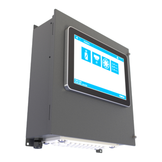
Figure 1. Halton Safe Management 2.0 controller Halton Safe Management 2.0 is a fire and smoke safety system that consists of a Halton Safe Management 2.0 controller combined with several Halton Safe HSL link units that manage Halton fire dampers and smoke detectors. -
Page 10: Operating Principle
2.2 Operating principle The Halton Safe Management 2.0 system can be modularly extended with up to 50 pieces of Halton Safe HSL link units to which the fire dampers and smoke detectors are connected. 1–4 fire dampers and 1–4 smoke detectors can be connected to each Halton Safe HSL link unit. - Page 11 Halton Safe Management 2.0 (SM2) - Installation, commissioning, operating, and maintenance guide Fire dampers (max. 4) Smoke detectors (max. 4) 230 VAC Total number of units (max. 4 x 50 = 200) 230 VAC OPTIONS Cloud Remote access Fire alarm...
-
Page 12: Structure And Components
Halton Safe Management 2.0 (SM2) - Installation, commissioning, operating, and maintenance guide 2.3 Structure and components Figure 3. Structure of Halton Safe Management 2.0 controller Part Details Controller case Painted metal, grey User interface Touch screen Label Product info All rights reserved ©Halton... -
Page 13: Dimensions And Weight
Halton Safe Management 2.0 (SM2) - Installation, commissioning, operating, and maintenance guide 2.4 Dimensions and weight Figure 4. Dimensions of Halton Safe Management 2.0 controller Weight: 4.1 kg 2.5 Further technical details For technical details on the product and its components, see Technical reference data. -
Page 14: Transport, Storage And Handling
3 Transport, storage and handling 3.1 Pre-packing and packing Prior to packing, Halton inspects all products fully for any damages or physical faults. Halton inspects all nameplates and identification tags against the purchase order and the Halton order confirmation to eliminate the possibility of any mistakes or issues. - Page 15 Halton Safe Management 2.0 (SM2) - Installation, commissioning, operating, and maintenance guide NOTICE NOTICE Do no use any part of the products for climbing or support. Protecting against moisture The pallets onto which the products are stored enable air circulation inside the plastic wrappings. It is a strict requirement that the products be stored in a dry indoor environment.
-
Page 16: Installation
Halton Safe Management 2.0 (SM2) - Installation, commissioning, operating, and maintenance guide 4 Installation 4.1 Before you start 4.1.1 Safety during installation WARNING ELECTRIC SHOCK HAZARD Before carrying out any electrical work, turn off the power to avoid injury from electrical current. -
Page 17: Installation Requirements
Halton Safe Management 2.0 (SM2) - Installation, commissioning, operating, and maintenance guide Note: Before connecting the system to power, you need to set the addresses of the Halton Safe HSL link units. For instructions, see Setting the address of a Halton Safe HSL link unit. -
Page 18: Installing A Halton Safe Hsl Link Unit
2. For detailed installation instructions, see the Calectro website. 4.2.6 Connecting a Halton Safe HSL link unit to the Halton Safe Management 2.0 controller Connect the wiring according to the connection or wiring diagrams. You can find the connection and wiring diagrams in Technical reference data. -
Page 19: Connecting A Halton Safe Hsp Power Unit To The Main Power Supply
NOTICE All electrical work must only be carried out by qualified personnel. Note: Do not connect a device that does not have its own fuse to the 24 V AC side of a Halton Safe HSP power unit. Connect the wires of the power supply cable to the connectors in the Halton Safe HSP unit. -
Page 20: Commissioning
Halton Safe HSL link unit addressing is defined during system commissioning. Each Halton Safe HSL link unit must have a unique address. The addresses are defined by using the DIP switches in the Halton Safe HSL link units. 5.1.4 Checks before commissioning Make sure you have the following: ▪... -
Page 21: Halton Safe Hsl Addresses
1, 2, 3, and 5 are set to ON. When the values are added together, you get the address of the Halton Safe HSL link unit in question: 32 + 16 + 8 + 2 = 58. This address belongs to Halton Safe HSL link unit number 48. -
Page 22: Logging In As Installer
2. On the keypad, type in password 01473, then select "Accept". 5.3.4 Configuring a Halton Safe HSL link unit Here you link a Halton Safe HSL link unit to the Halton Safe Management 2.0 controller. 1. Log in as Installer. For instructions, see Logging in as Installer. -
Page 23: Configuring A Fire Damper
Halton Safe Management 2.0 (SM2) - Installation, commissioning, operating, and maintenance guide 5.3.5 Configuring a fire damper Here you connect a fire damper to an alarm group (zone). You can also change the location (name) of the fire damper to make it easier to locate it. -
Page 24: Configuring A Smoke Detector Or An Alarm Device
Halton Safe Management 2.0 (SM2) - Installation, commissioning, operating, and maintenance guide Value Description The fire damper impacts all units. No impact Unit The fire damper impacts a link unit. Single The fire damper impacts a single fire damper. The fire damper is not closed with an external command except in a test situation and by an external fire alarm, if set accordingly. -
Page 25: Configuring A Fan
If you get errors when doing the task, see Troubleshooting. 5.3.7 Configuring a fan You can configure 1-3 fans for a Halton Safe Management 2.0 controller. By default, a fan is configured to stop in the following situations: ▪ An alarm group is being tested. - Page 26 Halton Safe Management 2.0 (SM2) - Installation, commissioning, operating, and maintenance guide 3. Remove the rule for fire damper action for alarm group (zone) "All". a. On row "All", select the "Dampers" column. b. In the selection window, select "-", then select "Change".
- Page 27 Halton Safe Management 2.0 (SM2) - Installation, commissioning, operating, and maintenance guide Value Description No impact Can start, when open The fan can start running when the fire damper is open. Need to be open, for start The fire damper needs to be open before the fan can start running.
-
Page 28: Configuring An Alarm Group (Zone)
Halton Safe Management 2.0 (SM2) - Installation, commissioning, operating, and maintenance guide Value Description No impact Fan stop The fan is stopped 7. To configure other fans, select one of the fan icons at the bottom of the view. 5.3.8 Configuring an alarm group (zone) 1. - Page 29 Halton Safe Management 2.0 (SM2) - Installation, commissioning, operating, and maintenance guide Value Description Normally open, closed by demand The damper is normally open, but closes when there is an alarm in the system. Normally closed, opened by demand The damper is normally closed, but opens when there is an alarm in the system.
-
Page 30: Configuring External Controls
2. Select the external zone control icon. The External zone control view opens. The "Connection" column shows the connections of the Halton Safe Management 2.0 controller for each external control. The external fire alarm shown at the lower part of the view is a general fire alarm that impacts all zones. - Page 31 Normally Closed (NC) alarm device 6. Make sure the connector type of the external fire system connected to the Halton Safe Management 2.0 system is correct. Select the "Connector" column on the row of the external fire alarm, then do as instructed in the previous step.
-
Page 32: Renaming A Unit
Halton Safe Management 2.0 (SM2) - Installation, commissioning, operating, and maintenance guide 5.3.10 Renaming a unit Here you change the location (name) of a unit, for example, to make it easier to locate it. 1. Log in as Installer. For instructions, see Logging in as Installer. -
Page 33: Setting The Type Of A Unit
If you get errors when doing the task, see Troubleshooting. 5.3.11 Setting the type of a unit Here you set the type of a unit, for example, a Halton Safe HSL link unit. 1. Log in as Installer. For instructions, see Logging in as Installer. - Page 34 Halton Safe Management 2.0 (SM2) - Installation, commissioning, operating, and maintenance guide 3. In the view that lists the units, on the row of the unit you want to configure, select the "Zone" column. 4. In the selection window, select the correct zone, then select "Change".
-
Page 35: Setting The Time And Date
Halton Safe Management 2.0 (SM2) - Installation, commissioning, operating, and maintenance guide If you get errors when doing the task, see Troubleshooting. 5.3.13 Setting the time and date Here you set the time and date of the system. You can also change the time zone or modify other clock-related settings. - Page 36 Halton Safe Management 2.0 (SM2) - Installation, commissioning, operating, and maintenance guide 4. In the schedule view, for a day of the week (Monday-Sunday), select the first empty slot. 5. In the selection window, select the alarm group (zone) and set the test time, then select "Change".
- Page 37 Halton Safe Management 2.0 (SM2) - Installation, commissioning, operating, and maintenance guide Value Description All units are tested. Unit A link unit is tested. Single A single fire damper is tested. A fire damper and a corresponding smoke detector on the same row are tested.
-
Page 38: Testing The System
Halton Safe Management 2.0 (SM2) - Installation, commissioning, operating, and maintenance guide 6. To copy the events of a day, do the following: a. In the schedule view, select "Copy events". b. In the selection window, select the days to copy from and to, then select "Copy". - Page 39 Halton Safe Management 2.0 (SM2) - Installation, commissioning, operating, and maintenance guide When the whole system is being tested, all the "Testing" toggle icons are green. 4. To test an alarm group (zone), in the Zone settings view, on the row of the zone, select the "Testing" toggle icon.
-
Page 40: Checks After Commissioning
Halton Safe Management 2.0 (SM2) - Installation, commissioning, operating, and maintenance guide 5. View the test report. For instructions, see Viewing a test report. 5.4 Checks after commissioning Make sure you have done the following: ▪ Document the test results and fill in the needed commissioning documents. -
Page 41: Operation
Halton Safe Management 2.0 (SM2) - Installation, commissioning, operating, and maintenance guide 6 Operation 6.1 User levels Halton Safe Management 2.0 has three user levels: ▪ Lookup ▪ Service ▪ Installer Lookup On this user level, you have basic user rights: ▪... - Page 42 Halton Safe Management 2.0 (SM2) - Installation, commissioning, operating, and maintenance guide Figure 7. Homepage (Service or Installer login required) Icons ▪ If an icon is grey, there are no units configured. ▪ If an icon is blue, there are units configured.
- Page 43 Halton Safe Management 2.0 (SM2) - Installation, commissioning, operating, and maintenance guide Figure 10. Fan icon Figure 11. Alarm list icon Figure 12. Zone settings icon Figure 13. Link unit icon Figure 14. External zone control icon All rights reserved ©Halton...
- Page 44 Halton Safe Management 2.0 (SM2) - Installation, commissioning, operating, and maintenance guide Figure 15. Homepage icon Views Figure 16. Dampers All rights reserved ©Halton...
- Page 45 Halton Safe Management 2.0 (SM2) - Installation, commissioning, operating, and maintenance guide Figure 17. Smoke Detectors Figure 18. Fan 1 All rights reserved ©Halton...
- Page 46 Halton Safe Management 2.0 (SM2) - Installation, commissioning, operating, and maintenance guide Figure 19. Alarm list Figure 20. Zone settings All rights reserved ©Halton...
-
Page 47: Step By Step Instructions
Halton Safe Management 2.0 (SM2) - Installation, commissioning, operating, and maintenance guide Figure 21. Link units Figure 22. External zone control 6.3 Step by step instructions 6.3.1 Switching between views 1. On the homepage, select an icon. 2. To return to the homepage, select the homepage icon at the bottom of the view. -
Page 48: Changing The Language Of The System
Halton Safe Management 2.0 (SM2) - Installation, commissioning, operating, and maintenance guide 6.3.2 Changing the language of the system 1. On the homepage, select "Change language". 2. In the selection window, select the language, then select "Change". 6.3.3 Changing the time and date Here you change the time and date of the system. - Page 49 Halton Safe Management 2.0 (SM2) - Installation, commissioning, operating, and maintenance guide 5. When the report is open, to print the report, select "Print Report". All rights reserved ©Halton...
-
Page 50: Maintenance
7.1.2 Checks before maintenance Make sure you have the following: ▪ A list of the ID numbers and locations of the Halton Safe Management 2.0 system components ▪ Access to the Halton Safe Management 2.0 system components ▪ The BMS event/alarm log of the most recent maintenance period 7.2 Maintenance schedule... -
Page 51: Resetting An Alarm
Halton Safe Management 2.0 (SM2) - Installation, commissioning, operating, and maintenance guide 2. On the keypad, type in password 20127, then select "Accept". 7.3.2 Resetting an alarm 1. Log in as Service. For instructions, see Logging in as Service. 2. Select the alarm list icon. -
Page 52: Resetting All Alarms
Halton Safe Management 2.0 (SM2) - Installation, commissioning, operating, and maintenance guide The system changes the status of the alarm to "Acknowledged". 4. Wait for a couple of minutes while the system opens the fire dampers. Once the fire dampers are open, the system continues working normally. -
Page 53: Testing The System
Halton Safe Management 2.0 (SM2) - Installation, commissioning, operating, and maintenance guide 3. Wait for a couple of minutes while the system opens the fire dampers. Once the fire dampers are open, the system continues working normally. 7.3.4 Testing the system Here you verify that the system is working as it should. - Page 54 Halton Safe Management 2.0 (SM2) - Installation, commissioning, operating, and maintenance guide When the whole system is being tested, all the "Testing" toggle icons are green. 4. To test an alarm group (zone), in the Zone settings view, on the row of the zone, select the "Testing" toggle icon.
-
Page 55: Modifying The Test Schedule
Halton Safe Management 2.0 (SM2) - Installation, commissioning, operating, and maintenance guide 5. View the test report. For instructions, see Viewing a test report. 7.3.5 Modifying the test schedule For instructions, see Setting up the test schedule. 7.3.6 Viewing a test report 1. - Page 56 Halton Safe Management 2.0 (SM2) - Installation, commissioning, operating, and maintenance guide 4. Fill in the date of the test and select the number of the test (0, 1, 2), then select "Show Report". All rights reserved ©Halton...
-
Page 57: Manually Controlling A Damper
Halton Safe Management 2.0 (SM2) - Installation, commissioning, operating, and maintenance guide 5. When the report is open, to print the report, select "Print Report". 7.3.7 Manually controlling a damper 1. Log in as Service. For instructions, see Logging in as Service. - Page 58 Halton Safe Management 2.0 (SM2) - Installation, commissioning, operating, and maintenance guide 4. In the selection window, select a status, then select "Change". Value Description Close The damper is closed. Open The damper is opened. After a while, you can see in the Dampers view that the status of the fire damper has changed.
-
Page 59: Changing The Time And Date
Halton Safe Management 2.0 (SM2) - Installation, commissioning, operating, and maintenance guide 5. When you no longer need to control the fire damper manually, remember to release the status of the fire damper. a. On the row of the fire damper, select the "Control" column. - Page 60 Halton Safe Management 2.0 (SM2) - Installation, commissioning, operating, and maintenance guide 4. From the upper table, select the link unit you want to update. 5. From the lower table, select the correct software version, then select "Add to send list".
-
Page 61: Replacing A Fuse
Halton Safe Management 2.0 (SM2) - Installation, commissioning, operating, and maintenance guide 7.3.10 Replacing a fuse 1. Disconnect the power cable of the Halton Safe Management 2.0 controller from the socket. 2. Replace the broken fuse. ▪ Halton Safe HSL, fuse type: SMD 2410 5 A F ▪... -
Page 62: End Of Life
Halton Safe Management 2.0 (SM2) - Installation, commissioning, operating, and maintenance guide 8 End of life 8.1 Removing the product from use 1. Disconnect the power cable of the Halton Safe Management 2.0 controller from the socket. 2. Disconnect the wiring. 3. Dismount the components of the system. -
Page 63: Troubleshooting And Repairs
Halton Safe Management 2.0 (SM2) - Installation, commissioning, operating, and maintenance guide 9 Troubleshooting and repairs 9.1 Troubleshooting Problem Possible cause Possible solution BMS bus communication does not Incorrect addressing or Make sure the link unit addressing is work router configured correct. -
Page 64: Spare Parts
Halton Safe Management 2.0 (SM2) - Installation, commissioning, operating, and maintenance guide 9.3 Spare parts For spare parts for your specific product, contact Halton. Provide the following information for easier service: ▪ Product ▪ Customer name/project ▪ Order confirmation number (purchase or sales order number) ▪... -
Page 65: Technical Reference Data
Halton Safe Management 2.0 (SM2) - Installation, commissioning, operating, and maintenance guide 10 Technical reference data 10.1 Connection diagrams and terminals 10.1.1 Connections: Halton Safe Management 2.0 controller Connection diagram Figure 23. Connection diagram: Halton Safe Management 2.0 controller All rights reserved ©Halton... - Page 66 Halton Safe Management 2.0 (SM2) - Installation, commissioning, operating, and maintenance guide Terminals Terminal Name Comment Relay 1 Fan control: 1 Relay 1 Relay 2 Fan control: 2 Relay 2 Relay 3 Fan control: 3 Relay 3 Relay 4 External fire alarm out...
- Page 67 Halton Safe Management 2.0 (SM2) - Installation, commissioning, operating, and maintenance guide Terminal Name Comment UI input 1 External alarm that closes user group: 1 UI input 2 External alarm that closes user group: 2 UI input 3 External alarm that closes user group: 3...
-
Page 68: Connections: Halton Safe Hsl
Halton Safe Management 2.0 (SM2) - Installation, commissioning, operating, and maintenance guide 10.1.2 Connections: Halton Safe HSL Connection diagram Figure 24. Connection diagram of Halton Safe HSL All rights reserved ©Halton... - Page 69 Halton Safe Management 2.0 (SM2) - Installation, commissioning, operating, and maintenance guide Terminals Terminal Actuator/sensor Comment Damper 1 Damper 1 Feedback from Smoke detector 1 Damper 2 Damper 2 Feedback from Smoke detector 2 S2, S6 Damper 1 S2, S6...
- Page 70 Halton Safe Management 2.0 (SM2) - Installation, commissioning, operating, and maintenance guide Terminal Actuator/sensor Comment Not in use Power Damper 1 Power Damper 1 Not in use Not in use Power Damper 2 Power Damper 2 Not in use Terminal...
-
Page 71: Connections: Halton Safe Hsp
Halton Safe Management 2.0 (SM2) - Installation, commissioning, operating, and maintenance guide Terminal Name Comment Internal bus, line B Internal bus, line A Not in use Not in use Not in use Internal use Internal use Input power 24 V AC Input power 24 V AC 10.1.3 Connections: Halton Safe HSP... -
Page 72: Connection Diagram: Halton Safe Hsr
Halton Safe Management 2.0 (SM2) - Installation, commissioning, operating, and maintenance guide Terminals Outlet power Terminal Comment G, Terminals for supply voltage connection + (24 V) G0, Terminals for supply voltage connection - (24 V) Inlet power Terminal Comment 230 V AC Line... -
Page 73: Connection Diagram: Halton Safe Hsd
Halton Safe Management 2.0 (SM2) - Installation, commissioning, operating, and maintenance guide 10.1.5 Connection diagram: Halton Safe HSD Figure 27. Connection diagram of Halton Safe HSD. R : Terminating resistor 2.2 kΩ. All rights reserved ©Halton... -
Page 74: Dip Switch Settings Of Halton Safe Hsl Link Units
Halton Safe Management 2.0 (SM2) - Installation, commissioning, operating, and maintenance guide 10.2 DIP switch settings of Halton Safe HSL link units DIP switch settings of Halton Safe HSL link units 1-20 (1 = ON, blank = OFF) HSL number... - Page 75 Halton Safe Management 2.0 (SM2) - Installation, commissioning, operating, and maintenance guide DIP switch settings of Halton Safe HSL link units 21-40 HSL number DIP 1 (32) DIP 2 (16) DIP 3 (8) DIP 4 (4) DIP 5 (2) DIP 6 (1)
- Page 76 Halton Safe Management 2.0 (SM2) - Installation, commissioning, operating, and maintenance guide DIP switch settings of Halton Safe HSL link units 41-50 HSL number DIP 1 (32) DIP 2 (16) DIP 3 (8) DIP 4 (4) DIP 5 (2) DIP 6 (1)
-
Page 77: Wiring Diagrams
Halton Safe Management 2.0 (SM2) - Installation, commissioning, operating, and maintenance guide 10.3 Wiring diagrams 10.3.1 Wiring diagram: Halton Safe Management 2.0 controller EXTERNAL BATTERY RELAY 1 FAN CONTROL :1 EXTERNAL BATTERY 12 VDC RELAY 2 FAN CONTROL :2 12 VDC... -
Page 78: Wiring Diagram: Halton Safe Hsl
Halton Safe Management 2.0 (SM2) - Installation, commissioning, operating, and maintenance guide 10.3.2 Wiring diagram: Halton Safe HSL Figure 29. Wiring diagram of Halton Safe HSL All rights reserved ©Halton... -
Page 79: Reports
Halton Safe Management 2.0 (SM2) - Installation, commissioning, operating, and maintenance guide 10.4 Reports 10.4.1 Commissioning report: Halton Safe Management 2.0 10.4.2 Commissioning report: Halton Safe HSL link unit tests All rights reserved ©Halton... - Page 80 Halton Safe Management 2.0 (SM2) - Installation, commissioning, operating, and maintenance guide All rights reserved ©Halton...
-
Page 81: Commissioning Report: Damper And Smoke Detector Tests
Halton Safe Management 2.0 (SM2) - Installation, commissioning, operating, and maintenance guide 10.4.3 Commissioning report: Damper and smoke detector tests All rights reserved ©Halton... - Page 82 Halton Safe Management 2.0 (SM2) - Installation, commissioning, operating, and maintenance guide All rights reserved ©Halton...
- Page 83 Halton Safe Management 2.0 (SM2) - Installation, commissioning, operating, and maintenance guide All rights reserved ©Halton...
- Page 84 Halton Safe Management 2.0 (SM2) - Installation, commissioning, operating, and maintenance guide All rights reserved ©Halton...
-
Page 85: Halton Safe Hsl
Figure 30. Structure of Halton Safe HSL Part Details I/O terminals Terminals for fire dampers and smoke detectors Bus connections Internal bus to Halton Safe Management 2.0 controller and Halton Safe HSL link units Indicators for bus communication 24 V fuse SMD 2410 5 A F... -
Page 86: Dimensions And Weight
Halton Safe Management 2.0 (SM2) - Installation, commissioning, operating, and maintenance guide 10.5.2 Dimensions and weight Figure 31. Dimensions of Halton Safe HSL Weight: 1.5 kg 10.6 Halton Safe HSP 10.6.1 Structure and components Figure 32. Structure of Halton Safe HSP... -
Page 87: Dimensions And Weight
Halton Safe Management 2.0 (SM2) - Installation, commissioning, operating, and maintenance guide Part Details 24 V AC terminals Power connections for Halton Safe HSL link units Transformer 260 VA Terminal for power supply 230 V AC 230 V AC fuse 10.6.2 Dimensions and weight... -
Page 88: Technical Reference Data: Parameters
Halton Safe Management 2.0 (SM2) - Installation, commissioning, operating, and maintenance guide 11 Technical reference data: Parameters 11.1 Halton Safe Management 2.0 BACnet parameter descriptions All rights reserved ©Halton...
Need help?
Do you have a question about the Safe Management 2.0 and is the answer not in the manual?
Questions and answers