Table of Contents
Advertisement
Quick Links
Z58-SN004
Special function: Additional adjustable tolerance window for preset-relay
incremental or absolute encoders
•
•
•
•
•
•
•
•
Z58-SN004-E_10-04
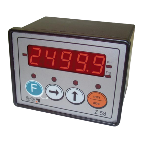
Universal Position Indicator for
lockable to inkremental- or
absolute encoders (FMAX, FEMAX, EMAX)
approved standard functions
(e.g. pulse scaling, multi-edge-counter,
Inch/mm-switch over)
three external inputs (+ 24 V)
serial interface RS-232
absolute-interface RS-422 (option)
analog input 0... 10 V or 0... 20 mA (option)
analog output 0... 10 V / 0 (4)...20 mA (option)
Optionally 2 shutter-relay-outputs (option)
Advertisement
Table of Contents

Related Manuals for ELGO Electronic Z58-SN004


Summary of Contents for ELGO Electronic Z58-SN004
- Page 1 Z58-SN004 Special function: Additional adjustable tolerance window for preset-relay Universal Position Indicator for incremental or absolute encoders lockable to inkremental- or • absolute encoders (FMAX, FEMAX, EMAX) approved standard functions • (e.g. pulse scaling, multi-edge-counter, Inch/mm-switch over) three external inputs (+ 24 V) •...
-
Page 2: Table Of Contents
1. GENERAL FEATURES 2. DISPLAY-WINDOWS, MONITOR-LEDS AND KEYPAD 3. OPERATION MODES 4. LIST OF PARAMETERS 5. FUNCTIONS OF PARAMETERS 6. FUNCTIONS OF THE KEYPAD AND OF EXTERNAL INPUTS 6.1 Reset 6.2 Absolute/Incremental mode 6.3 Additional tool-offset 6.4 Set to datum-value 6.5 How to activate the tolerance window? 7. -
Page 3: General Features
1. General features Power supply 24 VDC (standard) • 115/230 VAC (incremental systems only) • • Panel- or built-on housing available Cut out for panel 93 x 67 mm (w x h) • Install depth 73 mm (110 mm with D-SUB-Connector) •... -
Page 4: Display-Windows, Monitor-Leds And Keypad
2. Display-windows, Monitor-LEDs and keypad Sign Status Relays 1 (Option) lights up if counting lights up if activated value is negative Status Relays 2 (Option) lights up if activated Set to datum-value Keypad-LEDs Different monitoring functions Example with full configuration Tool offset * Entire/Relative measurement switch over* * Only in normal mode 3. -
Page 5: List Of Parameters
4. List of parameters To lock the programming-level of the menu, please press at the same time, for 3 seconds… Buttons F + Incr/Abs and it appears on Display Incr/Abs – Button Step up the Number of Parameter. With ▲ - and ►... -
Page 6: Functions Of Parameters
5. Functions of parameters P00 = Reserved for tests P01 = Switch over of counting direction P02 = Empty P03 = Selection of decimal point P04 = Activate or deactivate Power down memory here P05 = Select Keyboard interlock or enable here (parameter-level remains always active) P06 = Select multi-edge-counter here (x 1, x 2 x or x 4) P07 = Selection of measuring-system: The connected encoder system must be selected here! -
Page 7: Functions Of The Keypad And Of External Inputs
6. Functions of the keypad and of external inputs 6.1 Reset For setting the actual value to zero: Use the external input ST2/Pin6, and connect resp. close it for a short time to + 24 V to re- set the actual value. Please note: The external input is a statically input and is active, when it’s connected with + 24 V. -
Page 8: Teaching Procedure
7. Teaching procedure (only when using an ELGO FMAX absolute linear encoder) If an ELGO-FMAX encoder is connected, the following steps must be done, to calibrate and modulate the sensor with Z58: 1. Press for 3 sec., at the same time - in normal operation mode - Buttons - ►... -
Page 9: List Of Most Important Key-Functions
9. List of most important key-functions Normal mode: Datum value = at the same time Tool offset = Undo = Abs./Incr = switch over between “entire” and “relative” measurement Change to Programming mode = for 3 sec. at the same time Programming mode: Parameter step up =... -
Page 10: Serial Interface
10. Serial Interface Technology: Standard RS232 Data format: Baud rate = 9600 8 Data bits, 1 Stopbit, no parity Z58 answers only on request of the PC 10.1 Commands Readout the actual value: Command: STX ´i´ ETX Example: 02h 69h 03h Answer: e.g.. -
Page 11: Pin-Assignment
11. Pin-Assignment Connector ST5 Connector ST4 Connector ST2 Connector ST1 Connector ST3 Example rear with full configuration Inverted signals are marked with ’ Connector ST1 Connector ST3 (standard encoders): (absolute signals, relays, analog-output): 1: GND (output) 1: Screen/shield/PE 2: + 5 VDC/24 VDC (output) 2: GND (Encoder supply) 3: Channel A 3: + 24VDC (Encoder supply out) -
Page 12: Technical Specifications
12. Technical specifications 1) Position Indicator Z58.XXX.024 24 VDC - Version Power voltage 24 VDC +/- 20 % Consumption max. 70 mA (without measuring system) 2) Position Indicator Z58.XXX.230 resp. 115 (only incremental possible) 230 VAC or 115 VAC- Versions +/- 10 % 50 - 60 Hz Consumption max. -
Page 13: Type Designation
13. Type designation Z58 - XXX - XXX - X - XXXXXXX Position Indicator Universal single axis SN-Number 000 = Standard 001 = First special version 002 = Second special version etc. 054 = Replace type for Z54 Power supply voltage 024 = 24 VDC (+/- 20 %) 115 = 115 VAC - 50/60 Hz (+/- 10 %) only incremental possible 230 = 230 VAC - 50/60 Hz (+/- 10 %) only incremental possible... -
Page 14: Liability Exclusion / Guarantee
14. Liability exclusion / Guarantee We have checked the contents of this instruction manual carefully, to the best of our knowledge and belief for conformity with the described hardware and software. Nevertheless errors, mistakes or deviations can not be excluded, therefore we do not guarantee complete conformity.
Need help?
Do you have a question about the Z58-SN004 and is the answer not in the manual?
Questions and answers