
Related Manuals for WAGO 753-482


Summary of Contents for WAGO 753-482
- Page 1 Manual WAGO I/O System 750 753-482 2AI 4-20mA 12 Bit S.E. HART 2-Channel Analog Input; 4-20 mA; HART; Single-Ended (S.E.) Version 1.2.0...
- Page 2 We wish to point out that the software and hardware terms as well as the trademarks of companies used and/or mentioned in the present manual are generally protected by trademark or patent. WAGO is a registered trademark of WAGO Verwaltungsgesellschaft mbH. Manual Version 1.2.0...
-
Page 3: Table Of Contents
WAGO I/O System 750 Table of Contents 753-482 2AI 4-20mA 12 Bit S.E. HART Table of Contents Notes about this Documentation ............. 6 Validity of this Documentation..............6 Copyright ....................6 Symbols ....................7 Number Notation ..................9 Font Conventions ................... 9 Important Notes .................. - Page 4 Table of Contents WAGO I/O System 750 753-482 2AI 4-20mA 12 Bit S.E. HART 5.2.2 Removing the I/O Module ..............40 I/O Modules with Pluggable Wiring Level (Series 753) ......41 5.3.1 Coding ..................... 42 5.3.2 Plug Removal .................. 44 Connect Devices ..................
- Page 5 WAGO I/O System 750 Table of Contents 753-482 2AI 4-20mA 12 Bit S.E. HART List of Figures ....................97 List of Tables ....................99 Manual Version 1.2.0...
-
Page 6: Notes About This Documentation
This documentation is only applicable to the I/O module 753-482 (2AI 4-20mA 12 Bit S.E. HART). The I/O module 753-482 shall only be installed and operated according to the instructions in this manual and in the manual for the used fieldbus coupler or controller. -
Page 7: Symbols
WAGO I/O System 750 Notes about this Documentation 753-482 2AI 4-20mA 12 Bit S.E. HART Symbols Personal Injury! Indicates a high-risk, imminently hazardous situation which, if not avoided, will result in death or serious injury. Personal Injury Caused by Electric Current! Indicates a high-risk, imminently hazardous situation which, if not avoided, will result in death or serious injury. - Page 8 Notes about this Documentation WAGO I/O System 750 753-482 2AI 4-20mA 12 Bit S.E. HART Additional Information: Refers to additional information which is not an integral part of this documentation (e.g., the Internet). Manual Version 1.2.0...
-
Page 9: Number Notation
WAGO I/O System 750 Notes about this Documentation 753-482 2AI 4-20mA 12 Bit S.E. HART Number Notation Table 1: Number Notation Number Code Example Note Decimal Normal notation Hexadecimal 0x64 C notation Binary '100' In quotation marks, nibble separated '0110.0100' with dots (.) -
Page 10: Important Notes
2.1.1 Subject to Changes WAGO Kontakttechnik GmbH & Co. KG reserves the right to provide for any alterations or modifications. WAGO Kontakttechnik GmbH & Co. KG owns all rights arising from the granting of patents or from the legal protection of utility patents. -
Page 11: Technical Condition Of Specified Devices
These modules contain no parts that can be serviced or repaired by the user. The following actions will result in the exclusion of liability on the part of WAGO Kontakttechnik GmbH & Co. KG: •... -
Page 12: 2.1.4.1.2 Packaging
Important Notes WAGO I/O System 750 753-482 2AI 4-20mA 12 Bit S.E. HART Environmentally friendly disposal benefits health and protects the environment from harmful substances in electrical and electronic equipment. • Observe national and local regulations for the disposal of electrical and electronic equipment. -
Page 13: Safety Advice (Precautions)
WAGO I/O System 750 Important Notes 753-482 2AI 4-20mA 12 Bit S.E. HART Safety Advice (Precautions) For installing and operating purposes of the relevant device to your system the following safety precautions shall be observed: Do not work on devices while energized! All power sources to the device shall be switched off prior to performing any installation, repair or maintenance work. - Page 14 Important Notes WAGO I/O System 750 753-482 2AI 4-20mA 12 Bit S.E. HART Ensure proper contact with the DIN-rail! Proper electrical contact between the DIN-rail and device is necessary to maintain the EMC characteristics and function of the device. Replace defective or damaged devices! Replace defective or damaged device/module (e.g., in the event of deformed...
- Page 15 WAGO I/O System 750 Important Notes 753-482 2AI 4-20mA 12 Bit S.E. HART Avoid electrostatic discharge! The devices are equipped with electronic components that may be destroyed by electrostatic discharge when touched. Please observe the safety precautions against electrostatic discharge per DIN EN 61340-5-1/-3. When handling the devices, please ensure that environmental factors (personnel, work space and packaging) are properly grounded.
-
Page 16: Device Description
753-482 2AI 4-20mA 12 Bit S.E. HART Device Description The Analog Input Module 753-482 (2AI 4-20mA 12 Bit S.E. HART) processes analog signals with the norm value of 4 mA ... 20 mA. The I/O module also enables digital communication to be carried out with HART- enabled field devices (Highway Addressable Remote Transducer). - Page 17 The meaning of the LEDs is described in the “Display Elements” section. The I/O module 753-482 (2AI 4-20mA 12 Bit S.E. HART) receives the 24 V voltage supply for the field level from an upstream I/O module or from the fieldbus coupler/controller via blade-formed power jumper contacts.
-
Page 18: Table 4: Compatibility List
Device Description WAGO I/O System 750 753-482 2AI 4-20mA 12 Bit S.E. HART Table 4: Compatibility List Bus System Fieldbus Item No. Hard- Soft- Max. Function *) Coupler/ ware ware Number of Controller Version Version Modules 750-841 (1), (5) 750-842... -
Page 19: View
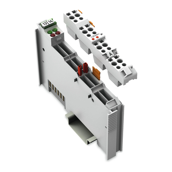
WAGO I/O System 750 Device Description 753-482 2AI 4-20mA 12 Bit S.E. HART View Depiction of the I/O module with 753-110 Plug! Information on this pluggable connection pertains to the 753-110 Plug, which is not included with the I/O module. -
Page 20: Connectors
Device Description WAGO I/O System 750 753-482 2AI 4-20mA 12 Bit S.E. HART Connectors 3.2.1 Data Contacts/Local Bus Communication between the fieldbus coupler/controller and the I/O modules as well as the system supply of the I/O modules is carried out via the local bus. The contacting for the local bus consists of 6 data contacts, which are available as self-cleaning gold spring contacts. -
Page 21: Power Jumper Contacts/Field Supply
The blade contacts are sharp-edged. Handle the I/O module carefully to prevent injury. Do not touch the blade contacts. The I/O module 753-482 has 2 self-cleaning power jumper contacts that supply and transmit power for the field side. The contacts on the left side of the I/O module are designed as blade contacts and those on the right side as spring contacts. - Page 22 Device Description WAGO I/O System 750 753-482 2AI 4-20mA 12 Bit S.E. HART Use supply modules for ground (earth)! The I/O module has no power jumper contacts for receiving and transmitting the earth potential. Use a supply module when an earth potential is needed for the subsequent I/O modules.
-
Page 23: Cage Clamp
WAGO I/O System 750 Device Description 753-482 2AI 4-20mA 12 Bit S.E. HART 3.2.3 CAGE CLAMP ® Connectors Depiction of the I/O module with 753-110 Plug! Information on this pluggable connection pertains to the 753-110 Plug, which is not included with the I/O module. -
Page 24: Display Elements
Device Description WAGO I/O System 750 753-482 2AI 4-20mA 12 Bit S.E. HART Display Elements Figure 5: Display Elements Table 8: Legend for Figure “Display Elements” Chan- Designation LED State Function Ready for operation: Green Power-On completed successfully; Function local bus communication... -
Page 25: Schematic Diagram
WAGO I/O System 750 Device Description 753-482 2AI 4-20mA 12 Bit S.E. HART Schematic Diagram Figure 6: Schematic Diagram Manual Version 1.2.0... -
Page 26: Technical Data
Device Description WAGO I/O System 750 753-482 2AI 4-20mA 12 Bit S.E. HART Technical Data 3.5.1 Device Table 9: Technical Data – Device Width 12 mm High (from upper edge of DIN 35 rail) 64 mm Length 100 mm Weight Approx. -
Page 27: Connection Type
WAGO I/O System 750 Device Description 753-482 2AI 4-20mA 12 Bit S.E. HART Table 12: Technical Data – Inputs Sensor connection 2-wire HART devices per channel 1 device (single-drop, no multi-drop) HART modems per channel 1 modem (no multiplex) 3.5.5 Connection Type Table 13: Technical Data –... -
Page 28: Approvals
Conformity Marking UL508 Korea Certification MSIP-REM-W43-AIM750 The following Ex approvals have been granted to 753-482 I/O modules: TÜV 07 ATEX 554086 X I M2 Ex d I Mb II 3 G Ex nA IIC T4 Gc II 3 D Ex tc IIIC T135°C Dc IECEx TUN 09.0001 X... -
Page 29: Standards And Guidelines
WAGO I/O System 750 Device Description 753-482 2AI 4-20mA 12 Bit S.E. HART Standards and Guidelines 753-482 I/O modules meet the following requirements on emission and immunity of interference: EMC CE-Immunity to interference EN 61000-6-2 EMC CE-Emission of interference EN 61000-6-4 Manual Version 1.2.0... -
Page 30: Process Image
Some fieldbus systems process status information on the input channel with the help of a status byte. This status byte can be displayed using the WAGO-I/O-CHECK commissioning tool but processing by the coupler/controller is optional; i.e., access to or evaluation of the status information depends on the respective fieldbus system. -
Page 31: Ai 4-20 Ma + 6-Byte Mailbox
The IEC application can be implemented in the connected programmable fieldbus controller (PFC) of the fieldbus node with the WAGO-I/O-PRO programming tool or, if a fieldbus coupler is connected, in the superimposed controller. -
Page 32: Table 18: Input Process Image
Process Image WAGO I/O System 750 753-482 2AI 4-20mA 12 Bit S.E. HART Table 18: Input Process Image Input Process Image Offset Designation of Bytes Remark Status byte Internal Use used internally MBX_RES Mailbox response data Analog input data Channel 1... -
Page 33: Ai 4-20 Ma, 1 Hart Variable Per Channel
WAGO I/O System 750 Process Image 753-482 2AI 4-20mA 12 Bit S.E. HART 4.1.1 2 AI 4-20 mA, 1 HART Variable per Channel With the PROFIBUS DP/V1 Fieldbus Coupler 750-333 or Fieldbus Controller 750-833, when one HART dynamic variable per channel is incorporated (optionally PV, SV, TV, QV), the PROFIBUS telegram has a size of 12 bytes. -
Page 34: Ai 4-20 Ma, 3 Hart Variables Per Channel
Process Image WAGO I/O System 750 753-482 2AI 4-20mA 12 Bit S.E. HART Table 23: PROFIBUS Telegram, 2 HART Variables per Channel PROFIBUS Telegram (2 Variables per Channel) Offset Designation of Bytes Remark Analog input data Channel 1 HV0_0 1st HART variable Channel 1... -
Page 35: Ai 4-20 Ma, 4 Hart Variables Per Channel
WAGO I/O System 750 Process Image 753-482 2AI 4-20mA 12 Bit S.E. HART Table 24: PROFIBUS Telegram, 3 HART Variables per Channel PROFIBUS Telegram (3 Variables per Channel) Offset Designation of Bytes Remark Analog input data Channel 1 HV0_0 1st HART variable Channel 1... -
Page 36: Table 25: Profibus Telegram, 4 Hart Variables Per Channel
Process Image WAGO I/O System 750 753-482 2AI 4-20mA 12 Bit S.E. HART Table 25: PROFIBUS Telegram, 4 HART Variables per Channel PROFIBUS Telegram (4 Variables per Channel) Offset Designation of Bytes Remark Analog input data Channel 1 Primary variable Channel 1... -
Page 37: Ai 4-20 Ma + Acyclic Profibus Services
Parameterizing the I/O Modules”/“Analog I/O Modules”/“2 AI Modules”. You will find these manuals on the Internet at: www.wago.com → Services → Downloads → Additional documentation and information on automation products → WAGO-I/O-SYSTEM 750 → Fieldbus Coupler and Programmable Fieldbus Controller The status bytes provide status information on the input channels. -
Page 38: Mounting
Always plug a bus end module (750-600) onto the end of the fieldbus node! You must always use a bus end module at all fieldbus nodes with WAGO I/O System 750 fieldbus couplers or controllers to guarantee proper data transfer. -
Page 39: Inserting And Removing Devices
WAGO I/O System 750 Mounting 753-482 2AI 4-20mA 12 Bit S.E. HART Inserting and Removing Devices Do not work when devices are energized! High voltage can cause electric shock or burns. Switch off all power to the device prior to performing any installation, repair or maintenance work. -
Page 40: Removing The I/O Module
Mounting WAGO I/O System 750 753-482 2AI 4-20mA 12 Bit S.E. HART 5.2.2 Removing the I/O Module Note Remove pluggable wiring! Before removing a 753 Series I/O Module from the node, you must first remove the plug (pluggable wiring) from the I/O module (see section “Plug Removal”)! -
Page 41: I/O Modules With Pluggable Wiring Level (Series 753)
WAGO I/O System 750 Mounting 753-482 2AI 4-20mA 12 Bit S.E. HART I/O Modules with Pluggable Wiring Level (Series 753) For wiring, a plug is plugged into the bottom of the module of all 753 Series I/O modules. The plug can be completely removed together with the wiring, simplifying replacement of defective modules from the assembly. -
Page 42: Coding
Mounting WAGO I/O System 750 753-482 2AI 4-20mA 12 Bit S.E. HART Figure 12: Attachment of Cable Binders 5.3.1 Coding Coding using small plastic pins and sockets facilitates mating of the I/O module with the appropriate plug. Insert the pin into the socket. -
Page 43: Figure 15: Plugging The Plug Into Place
WAGO I/O System 750 Mounting 753-482 2AI 4-20mA 12 Bit S.E. HART Figure 15: Plugging the Plug into Place When the plug is removed the sockets remain in the I/O module. The coded plug can only fit in the corresponding coded I/O module (see figures below). -
Page 44: Plug Removal
Mounting WAGO I/O System 750 753-482 2AI 4-20mA 12 Bit S.E. HART 5.3.2 Plug Removal Remove the plug from the I/O module by pulling the orange pull tab on the plug toward the top of the I/O module. Figure 17: Pulling the Pull Tab The plug detaches from the I/O module. -
Page 45: Connect Devices
Do not connect more than one conductor at one single connection! If more than one conductor must be routed to one connection, these must be connected in an up-circuit wiring assembly, for example using WAGO feed- through terminals. For opening the CAGE CLAMP ®... -
Page 46: Connection Examples
753-614, which is required to connect passive 3-conductor HART sensors as well as active HART sensors, and of the HART I/O module 753-482.. Figure 21: Connection Views and Circuit Diagrams of I/O Modules 753-614 and 753-482 Manual Version 1.2.0... -
Page 47: Connecting Passive Hart Sensors
WAGO I/O System 750 Connect Devices 753-482 2AI 4-20mA 12 Bit S.E. HART 6.2.1 Connecting Passive HART Sensors 6.2.1.1 Connecting a 2-Conductor HART Sensor One or two passive 2-conductor HART sensors can be connected directly to the HART+ and HART- connections. The passive sensors are supplied with 24 VDC directly from the I/O module. -
Page 48: Connecting A 3-Conductor Hart Sensor
753-614) must be connected upstream for the 0 V potential. The HART+ and HART- sensors are connected to the HART+ and HART- terminal points of the HART module 753-482. The passive sensors are supplied with 24 VDC directly from the I/O module. -
Page 49: Connecting An Active 24 Vdc Hart Sensor
WAGO I/O System 750 Connect Devices 753-482 2AI 4-20mA 12 Bit S.E. HART 6.2.2.1 Connecting an Active 24 VDC HART Sensor Figure 24: Connecting an Active 24 VDC HART Sensor 6.2.2.2 Connecting an active 230 VAC HART Sensor Figure 25: Connecting an Active 230 VAC HART Sensor Manual Version 1.2.0... -
Page 50: Function Description
WAGO as a free download. FDT tool routing to the DTM of the connected HART device is possible in default operating mode for connecting the I/O module to various WAGO ETHERNET controllers with the help of the 759-359 ModbusTCP/HART Gateway DTM. - Page 51 WAGO I/O System 750 Function Description 753-482 2AI 4-20mA 12 Bit S.E. HART Additional Information about HART Technology You will find more detailed information on HART technology on the HART Communication Foundation website (HCF user organization) at: www.hartcomm.org Manual Version 1.2.0...
-
Page 52: Operating Modes
2-channel analog input module for 4 mA … 20 mA signals with HART functionality. In this default operating mode the I/O module can be connected to all WAGO couplers and controllers listed in the table “Compatibility List”. In this case, HART communication is enabled by a 6-byte mailbox, which is incorporated with the analog values in the cyclic process image. -
Page 53: Setting Up Using Wago-I/O-Check
8.1.1 Setting Up using WAGO-I/O-CHECK It is only necessary to set the parameters of the HART I/O module using WAGO- I/O-CHECK when the default operating mode (2AI + 6-byte mailbox) has been changed to the “PROFIBUS operating mode” (2 AI + acyclic PROFIBUS services) and is then to be changed back to the default mode. -
Page 54: Figure 26: Wago-I/O-Check Context Menu „Settings
Operating Modes WAGO I/O System 750 753-482 2AI 4-20mA 12 Bit S.E. HART In this window under Connection select “Serial ports (COM, USB, Bluetooth, ...)” and under Port “COM1: Communications port”. Then confirm this selection by clicking [OK]. Switch on the supply voltage to your coupler/controller. -
Page 55: Figure 28: Wago-I/O-Check Message For Successfully Parameterizing
753-482 2AI 4-20mA 12 Bit S.E. HART Figure 28: WAGO-I/O-CHECK Message for Successfully Parameterizing Additional Information about WAGO-I/O-CHECK You will find a detailed description of the functions and use of the commissioning tool in the 759-302 WAGO-I/O-CHECK manual on the Internet under: www.wago.com Manual Version 1.2.0... -
Page 56: Setting Up Via Gsd
GSD files. Additional Information for Download the GSD Files The GSD files can be downloaded free of charge from the WAGO website at: www.wago.com → Support → Additional documentation and information on automation products →... -
Page 57: Figure 29: Gsd Configuration
WAGO I/O System 750 Operating Modes 753-482 2AI 4-20mA 12 Bit S.E. HART Figure 29: GSD Configuration To open the parameterization dialog to the selected module, click on the button with three points [...] in the “UsrPrm” (User Parameter) column. -
Page 58: Figure 30: Parameterization Dialog For Selecting 75X-482 2Ai/4-20 Ma/Se
Operating Modes WAGO I/O System 750 753-482 2AI 4-20mA 12 Bit S.E. HART 75x-482 2AI/4-20 mA/SE Figure 30: Parameterization dialog for selecting 75x-482 2AI/4-20 mA/SE Manual Version 1.2.0... -
Page 59: Table 31: General Parameter Data
WAGO I/O System 750 Operating Modes 753-482 2AI 4-20mA 12 Bit S.E. HART Parameters for all Operating Modes Table 31: General Parameter Data Parameter Value Description Terminal is • Plugged • I/O module is physically plugged in physically • Unplugged •... -
Page 60: Fdt/Dtm Concept
Operating Modes WAGO I/O System 750 753-482 2AI 4-20mA 12 Bit S.E. HART Selection Parameters for 75x-482 2AI/(1, 2, 3)x2 HV) Table 32: Parameter Data for the HART Variables Parameter Value Description 1×2 HV: 1 HART variable Channel 1 / 2;... -
Page 61: Figure 31: Fdt/Dtm Communication Principle
WAGO provides a simple and convenient FDT frame application in the form of the “759 370 WAGOframe FDT Frame Application” software. Additional Information about WAGOframe Please read the “759 370 WAGOframe FDT Frame Application”... -
Page 62: Hart On Profibus
Operating Modes WAGO I/O System 750 753-482 2AI 4-20mA 12 Bit S.E. HART Additional Information about the Download of the HARTGatewayDTMs The gateway DTMs for PROFIBUS (759-360 Profibus/HARTGatewayDTM) and MODBUS TCP (759-359 ModbusTCP/HARTGatewayDTM) are available for downloading free of charge from the Internet at: www.wago.com... -
Page 63: Commissioning
With PLC Library on All Compatible 75x-xxx Fieldbus Couplers/Controllers With the default parameter settings “2 AI + 6-Byte Mailbox”, the HART I/O module can be used with all WAGO fieldbus couplers/controllers 75x-xxx of the WAGO-I/O-SYSTEM with HART functionality, which are listed in the Section “Compatibility List”. -
Page 64: Communication On 75X-Xxx Via Plc Library
You can read a detailed description with a clear application example for the “WagoLibHART_0x.lib“ library with WAGO-I/O-PRO CAA in the respective application note that describes the HARD application using this library. You can download this application note from the WAGO homepage at: www.wago.com Enter the search term “WagoLibHART”. -
Page 65: Startup On The 75X-Xxx Via Plc Library
PROFIBUS system, the operating mode must be parameterized again for the default setting Launch WAGO-I/O-CHECK and set the operating mode to “2 AI + 6-byte mailbox”. Proceed as described in the Section “Operating Modes” > … > “Setting via WAGO-I/O-CHECK”. -
Page 66: Fdt/Dtm With The Ethernet Controller 750-841
Figure 34: WAGO-I/O-PRO Project with Integrated “WagoLibHART_0x.lib” Library More information about WAGO-I/O-PRO CAA Detailed descriptions of the functions and use of the WAGO-I/O-PRO CAA IEC 61131-3 programming tool are available in the WAGO-I/O-PRO CAA (759-333) manual on the Internet at: www.wago.com FDT/DTM with the ETHERNET Controller 750-841 In the default mode “2AI + 6-byte mailbox”, when the HART I/O module is... -
Page 67: Communication On 750-841 Via Fdt/Dtm
You can download this boot project and more detailed information relating to it on the WAGO website at: www.wago.com → Support → Additional documentation and information on automation products → Application Notes, under the number: “A116101”. The device driver “ModbusTCP/HARTGatewayDTM 759-359” is available for the convenient FDT/DTM frame application “WAGOframe”, which makes it possible... -
Page 68: Commissioning 750-841 Via Fdt/Dtm
If this should already have been changed; e.g., if the module has been used in a PROFIBUS system, the operating mode must be re- parameterized for the default setting. To do this, open WAGO-I/O-CHECK, and set the operating mode to Manual Version 1.2.0... -
Page 69: Figure 36: Ftp Access On A Fieldbus Controller
WAGO I/O System 750 Commissioning 753-482 2AI 4-20mA 12 Bit S.E. HART “2 AI + 6-byte mailbox”. For this purpose, proceed as described in the section “Operating Modes” > … > “Setting Up using WAGO-I/O-CHECK”. Restriction of Settings for PROFIBUS Operating Mode! This changeover and operation with other than a PROFIBUS Coupler 750-333 or Controller 750-833 is not yet possible at the present time for “PROFIBUS... - Page 70 Move the mouse to “Network” in the tree structure and click on Add... in the context menu (right mouse button). Select “WAGO Modbus TCP” in the dialog which opens and confirm the selection by clicking [OK]. The entry “MODBUS TCP_DTM*” will now be added to the tree structure.
-
Page 71: With Hart Dynamic Variables On Profibus Dp/V1 750-333 And 750-833
WAGO I/O System 750 Commissioning 753-482 2AI 4-20mA 12 Bit S.E. HART Now move the mouse to “<ModbusCommChannel:-> 075x-08xx DTM*” in the tree structure and click on [Add...] in the context menu (right mouse button). Select the HART DTM for your HART field device in the dialog which opens and confirm the selection by clicking [OK]. -
Page 72: Table 36: Operating Mode For Profibus Dp/V1
Because of the process data capacity of the HART I/O module, please be sure to take into account the corresponding maximum number of modules that can be connected when using a WAGO PROFIBUS DP/V1 Coupler 750-333 or Controller 750-833. You can find this number in the table “Compatibility List”. -
Page 73: Communication On The 750-333, -833 With Dynamic Variables
9.3.1 Communication on the 750-333, -833 with Dynamic Variables The use of the HART I/O module with a WAGO PROFIBUS DP/V1 Coupler 750- 333 or Controller 750-833 is described briefly below. Figure 37: System Overview with a PROFIBUS Fieldbus Coupler/Controller The WAGO fieldbus node with PROFIBUS DP/V1 coupler/controller serves as a data gatherer/distributor for the superimposed controller. -
Page 74: Table 37: Software Required For The Commissioning On
(SIMATIC Manager,…) environment A PROFIBUS Coupler 750-333 or Controller 750-833 is operated on a PROFIBUS master; e.g., on a 750-870 WAGO IPC, an S7 or another PROFIBUS master station. In this case, WAGO-I/O-PRO CAA (Item No.: 759-333), the “SIMATIC Manager”... -
Page 75: Fdt/Dtm With The Profibus Dp/V1 750-333, 750-833
WAGO I/O System 750 Commissioning 753-482 2AI 4-20mA 12 Bit S.E. HART Now expand the device catalog and using “Drag&Drop” add the remaining I/O modules that you have plugged into your fieldbus node on the coupler/controller. In doing so, you will find a total of five entries for the HART I/O Module corresponding to the operating modes. -
Page 76: Communication On 750-333, -833 Via Fdt/Dtm
Because of the process data capacity of the HART I/O module, please be sure to take into account the corresponding maximum number of modules that can be connected when using a WAGO PROFIBUS DP/V1 Coupler (750-333) or Controller (750-833). You can find this number in the list of the table “Compatibility List”. -
Page 77: Commissioning On A 750-333, -833 Via Fdt/Dtm
“Operating Modes“ > … > “Setting Up via GSD”. Alternatively you can also open WAGO-I/O-CHECK if available. In this case, proceed as described in the section “Operating Modes Parameters” > … > “Setting Up using WAGO-I/O-CHECK”. -
Page 78: Figure 40: Dialog Window "Device List
Commissioning WAGO I/O System 750 753-482 2AI 4-20mA 12 Bit S.E. HART click on Add... in the context menu (right mouse button). Select the device type name for your PROFIBUS master in the dialog which opens and confirm the selection by clicking [OK]. -
Page 79: Figure 41: Dialog Window 750-333 Configuration, Register Device Information
WAGO I/O System 750 Commissioning 753-482 2AI 4-20mA 12 Bit S.E. HART coupler/controller, for the “DP slave address” in the new view. Confirm your entry by clicking [Close]. Use the mouse to select the communications DTM in the tree structure and right click on Configuration in the context menu. -
Page 80: Figure 42: Dialog Window 750-333 Configuration, Register Module
Commissioning WAGO I/O System 750 753-482 2AI 4-20mA 12 Bit S.E. HART Figure 42: Dialog Window 750-333 Configuration, Register Module Configuration Select the register Parameterization and open a dialog view in which you can make additional parameter changes. Confirm the changes made here by clicking [Apply]. -
Page 81: Figure 43: Dialog Window 750-333 Configuration, Register Parameterization
WAGO I/O System 750 Commissioning 753-482 2AI 4-20mA 12 Bit S.E. HART Figure 43: Dialog Window 750-333 Configuration, Register Parameterization When configuration is completed, close the configuration dialog window. Use the mouse to select the communications DTM in the tree structure and right click on Offline Parameterization in the context menu. -
Page 82: Figure 44: Dialog Window Dtm Parameters
Commissioning WAGO I/O System 750 753-482 2AI 4-20mA 12 Bit S.E. HART Figure 44: Dialog Window DTM Parameters Select the desired module from the left side of the tree structure; the displayed module number corresponds to the slot in the structure – module 01 is the bus coupler. -
Page 83: Figure 45: Dialog Window Detail: Setting For Channel 1
WAGO I/O System 750 Commissioning 753-482 2AI 4-20mA 12 Bit S.E. HART Figure 45: Dialog Window Detail: Setting for Channel 1 Proceed in the same manner for all additional modules. When parameter settings are complete, confirm by clicking [OK]. Move the mouse to the entry for the PROFIBUS/HART communications DTM in the tree structure, select it by clicking with the left mouse button, and then click Set up connection on the Device menu. -
Page 84: Figure 47: Dialog Window Device List, Update
Commissioning WAGO I/O System 750 753-482 2AI 4-20mA 12 Bit S.E. HART Depending on the entry “<M01_Ch01>...HART DTM*” or “<M01_Ch01>...HART DTM*” will be added in the tree structure. If a HART device is connected to both channels, carry out these steps for the first channel and then again in a similar manner for the second channel. -
Page 85: Use In Hazardous Environments
Use in Hazardous Environments 753-482 2AI 4-20mA 12 Bit S.E. HART Use in Hazardous Environments The WAGO I/O SYSTEM 750 (electrical equipment) is designed for use in Zone 2 hazardous areas and shall be used in accordance with the marking and installation regulations. -
Page 86: Marking Configuration Examples
Use in Hazardous Environments WAGO I/O System 750 753-482 2AI 4-20mA 12 Bit S.E. HART 10.1 Marking Configuration Examples 10.1.1 Marking for Europe According to ATEX and IECEx Figure 48: Marking Example According to ATEX and IECEx Figure 49: Text Detail – Marking Example According to ATEX and IECEx Manual Version 1.2.0... -
Page 87: Table 39: Description Of Marking Example According To Atex And Iecex
WAGO I/O System 750 Use in Hazardous Environments 753-482 2AI 4-20mA 12 Bit S.E. HART Table 39: Description of Marking Example According to ATEX and IECEx Marking Description TUEV 07 ATEX 554086 X Approving authority resp. certificate numbers IECEx TUN 09.0001 X... -
Page 88: Figure 50: Marking Example For Approved Ex I I/O Module According To
Use in Hazardous Environments WAGO I/O System 750 753-482 2AI 4-20mA 12 Bit S.E. HART Figure 50: Marking Example for Approved Ex i I/O Module According to ATEX and IECEx Figure 51: Text Detail – Marking Example for Approved Ex i I/O Module According to ATEX and... -
Page 89: Table 40: Description Of Marking Example For Approved Ex I I/O Module According To Atex And Iecex
WAGO I/O System 750 Use in Hazardous Environments 753-482 2AI 4-20mA 12 Bit S.E. HART Table 40: Description of Marking Example for Approved Ex i I/O Module According to ATEX and IECEx Marking Description TUEV 12 ATEX 106032 X Approving authority resp. certificate numbers... -
Page 90: Marking For The United States Of America (Nec) And Canada (Cec)
Use in Hazardous Environments WAGO I/O System 750 753-482 2AI 4-20mA 12 Bit S.E. HART 10.1.2 Marking for the United States of America (NEC) and Canada (CEC) Figure 52: Marking Example According to NEC Figure 53: Text Detail – Marking Example According to NEC 500... -
Page 91: Figure 54: Text Detail - Marking Example For Approved Ex I I/O Module
WAGO I/O System 750 Use in Hazardous Environments 753-482 2AI 4-20mA 12 Bit S.E. HART Figure 54: Text Detail – Marking Example for Approved Ex i I/O Module According to NEC 505 Table 42: Description of Marking Example for Approved Ex i I/O Module According to NEC 505... -
Page 92: Figure 56: Text Detail - Marking Example For Approved Ex I I/O Modules
Use in Hazardous Environments WAGO I/O System 750 753-482 2AI 4-20mA 12 Bit S.E. HART Figure 56: Text Detail – Marking Example for Approved Ex i I/O Modules According to CEC 18 attachment J Table 44: Description of Marking Example for Approved Ex i I/O Modules According to CEC 18... -
Page 93: Installation Regulations
WAGO I/O System 750 Use in Hazardous Environments 753-482 2AI 4-20mA 12 Bit S.E. HART 10.2 Installation Regulations For the installation and operation of electrical equipment in hazardous areas, the valid national and international rules and regulations which are applicable at the installation location must be carefully followed. - Page 94 Use in Hazardous Environments WAGO I/O System 750 753-482 2AI 4-20mA 12 Bit S.E. HART Explosive atmosphere occurring simultaneously with assembly, installation or repair work must be ruled out. Among other things, these include the following activities • Insertion and removal of components •...
-
Page 95: Special Notes Regarding Ansi/Isa Ex
WAGO I/O System 750 Use in Hazardous Environments 753-482 2AI 4-20mA 12 Bit S.E. HART 10.2.2 Special Notes Regarding ANSI/ISA Ex For ANSI/ISA Ex acc. to UL File E198726, the following additional requirements apply: • Use in Class I, Division 2, Group A, B, C, D or non-hazardous areas only •... -
Page 96: Appendix: Information For Hart Library
“Device Specific Commands.” Additional information for downloading the library The library can be downloaded from the WAGO Internet site at www.wago.com → Support → Additional documentation and information on automation products → WAGO Software → WAGO-I/O-PRO / CODESYS → (right column, “Additional Information”:) Libraries →... - Page 97 Figure 24: Connecting an Active 24 VDC HART Sensor ........49 Figure 25: Connecting an Active 230 VAC HART Sensor ........49 Figure 26: WAGO-I/O-CHECK context menu „Settings“ ........54 Figure 27: WAGO-I/O-CHECK Dialog Window “Settings for 0750-0482” ....54 Figure 28: WAGO-I/O-CHECK Message for Successfully Parameterizing ..55 Figure 29: GSD Configuration ................57 Figure 30: Parameterization dialog for selecting 75x-482 2AI/4-20 mA/SE ..58...
- Page 98 List of Figures WAGO I/O System 750 753-482 2AI 4-20mA 12 Bit S.E. HART Figure 44: Dialog Window DTM Parameters ............82 Figure 45: Dialog Window Detail: Setting for Channel 1 ........83 Figure 46: Channel Selection Dialog Window .............83 Figure 47: Dialog Window Device List, Update ...........84 Figure 48: Marking Example According to ATEX and IECEx ......86...
- Page 99 WAGO I/O System 750 List of Tables 753-482 2AI 4-20mA 12 Bit S.E. HART List of Tables Table 1: Number Notation ................... 9 Table 2: Font Conventions .................. 9 Table 3: Types of Application ................16 Table 4: Compatibility List ..................18 Table 5: Legend for Figure “View”...
- Page 100 100 List of Tables WAGO I/O System 750 753-482 2AI 4-20mA 12 Bit S.E. HART Table 43: Description of Marking Example for Approved Ex i I/O Modules According to NEC 506 ................91 Table 44: Description of Marking Example for Approved Ex i I/O Modules According to CEC 18 attachment J ............92...
- Page 101 WAGO I/O System 750 List of Tables 101 753-482 2AI 4-20mA 12 Bit S.E. HART Manual Version 1.2.0...
- Page 102 WAGO Kontakttechnik GmbH & Co. KG Postfach 2880 • D - 32385 Minden Hansastraße 27 • D - 32423 Minden Phone: +49 571 887 – 0 Fax: +49 571 887 – 844169 E-Mail: info@wago.com Internet: www.wago.com...
Need help?
Do you have a question about the 753-482 and is the answer not in the manual?
Questions and answers