Table of Contents
Advertisement
Advertisement
Table of Contents
Troubleshooting

Related Manuals for Suzuki SMD16


Summary of Contents for Suzuki SMD16
- Page 1 Multi-Function Display OPERATOR’S MANUAL (Elemental Chlorine Free) The paper used in this manual is elemental chlorine free. A: DEC. 07, 2018 Pub. No. OME-45060-A (201812) SMD12/SMD16 00019546410 Part No. 34916-98L20 Dec, 2018 Eng. Printed in Japan 300 TAKATSUKA, MINAMI, HAMAMATSU, JAPAN...
- Page 2 How to discard a used battery Some SUZUKI products have a battery(ies). To see if your product has a battery, see the chapter on Maintenance. Follow the instructions below if a battery is used. Tape the + and - terminals of battery before disposal to prevent fire, heat generation caused by short circuit.
- Page 3 SAFETY INSTRUCTIONS Read these safety instructions before you operate the equipment. WARNING Indicates a condition that can cause death or serious injury if not avoided. Indicates a condition that can cause minor or moderate CAUTION injury if not avoided. Warning, Caution Prohibitive Action Mandatory Action WARNING...
- Page 4 SAFETY INSTRUCTIONS CAUTION WARNING The fish finder picture is not Keep units other than the radar refreshed when the picture antenna away from rain and advance setting is “OFF”. water. Do not use high-pressure cleaners Fire or electrical shock can occur if to clean this equipment.
- Page 5 Safety Labels malfunction. A safety label is attached to the display unit. Do not remove the label. If the label is missing or damaged, contact a SUZUKI agent or dealer about replacement. Name: Warning Label (1) WARNING Type: 86-003-1011-3 To avoid electrical shock, do not remove cover.
-
Page 6: Table Of Contents
TABLE OF CONTENTS FOREWORD ......................... xiv SYSTEM CONFIGURATION ..................xvi SYSTEM INTRODUCTION ..................1-1 1.1 Controls ........................1-2 1.2 Remote Control Units (option) ................... 1-5 1.2.1 Remote Control MCU-002 ................1-5 1.2.2 Remote Control Unit MCU-004..............1-6 1.2.3 Control Unit MCU-005 ................... 1-7 1.2.4 Remote Control Unit group settings .............. - Page 7 TABLE OF CONTENTS 2.3 Troll Mode .......................2-14 2.3.1 How to Use the Troll..................2-14 2.3.2 How to display and operate from the slide-out menu........2-14 2.3.3 How to cancel the troll mode................2-15 2.4 QR Code ........................2-16 2.4.1 How to create QR Code ................2-16 2.4.2 How to view QR Code logs ................2-17 2.4.3...
- Page 8 TABLE OF CONTENTS 3.12 Plotter Menu ......................3-24 3.13 NAVpilot Series Auto Pilot ..................3-25 3.13.1 How to enable use of the NAVpilot.............. 3-25 3.13.2 How to show the NAVpilot control box in the data area ......3-26 3.13.3 How to make an automated turn with the NAVpilot ........3-26 3.13.4 How to change the NAVpilot settings ............
- Page 9 TABLE OF CONTENTS 5.13 How to Go to a Point ....................5-14 5.13.1 How to go to an on-screen point ..............5-14 5.13.2 How to go to a position selected on screen ..........5-15 5.13.3 How to go to a point selected from the points list.........5-16 5.13.4 How to use the NAVpilot to steer to a point ..........5-16 5.13.5 How to display the point information for the active goto point......5-17 5.14 How to Restart or Cancel Navigation to a Point............5-17...
- Page 10 TABLE OF CONTENTS 6.14 Laylines ........................6-17 6.14.1 How to enable/disable the layline feature............ 6-17 6.14.2 How to show layline data in the data area........... 6-17 6.14.3 How to change the polar wind file..............6-18 6.15 Routes Menu ......................6-18 RADAR ........................7-1 7.1 How to Transmit, Set the Radar in Stand-by .............
- Page 11 TABLE OF CONTENTS 7.28 ARPA Operation.......................7-32 7.28.1 How to show or hide the ARPA display............7-32 7.28.2 How to manually acquire a target..............7-33 7.28.3 How to automatically acquire a target ............7-33 7.28.4 How to automatically acquire targets by Doppler.........7-33 7.28.5 How to display target data................7-34 7.28.6 How to stop tracking targets.................7-34 7.28.7 ARPA list ......................7-35 7.28.8 How to clear lost targets................7-36...
- Page 12 TABLE OF CONTENTS MULTI BEAM SONAR FURUNO DFF-3D.............9-1 9.1 Display Screens Overview..................9-1 9.2 Multi-Sounder Display Operations................9-4 9.2.1 How to switch between TX and STBY............9-4 9.2.2 How to switch between single beam and triple beam presentations ..... 9-4 9.2.3 How to set the TX beam angle ..............
- Page 13 TABLE OF CONTENTS 11.5 Tracking Active Waypoint, MOB ................11-7 11.6 Touch Control on the Camera Display ..............11-8 11.7 FUSION-Link......................11-9 11.7.1 How to access the FUSION screen and controls.........11-9 11.7.2 FUSION settings ..................11-11 12. SIRIUS/XM SATELLITE WEATHER RECEIVER (BBWX3) OPERATIONS ..12-1 12.1 Marine Weather Display Introduction ...............12-1 12.2 NavCenter Weather ....................12-2 12.2.1 How to set up for NavCenter weather ............12-2...
- Page 14 TABLE OF CONTENTS 14. OTHER FUNCTIONS ...................14-1 14.1 General Menu......................14-1 14.2 Units Menu ......................14-3 14.3 Initial Setup Menu....................14-4 14.4 Facsimile Receiver FURUNO FAX-30..............14-10 14.5 How to Manage Your Charts ................. 14-11 14.5.1 How to view your charts ................14-11 14.5.2 How to hide unnecessary charts on the chart catalog list ......
-
Page 15: Foreword
Congratulations on your choice of the Multi-Function Display SMD12/16. We are confident you will see why the SUZUKI name has become synonymous with quality and reliability. This equipment is designed and constructed to meet the rigorous demands of the marine environ- ment. - Page 16 FOREWORD ™ • ACCU-FISH provides at-a-glance estimation of length and depth of individual fish. • Bottom discrimination display helps identify probable bottom composition with graphics and col- ors. ™ ™ • RezBoost raises echo resolution to see fish echoes clearly. (Requires RezBoost capable transducer.
-
Page 17: System Configuration
Use an after-market PoE hub. The NETGEAR GS108PE is confirmed as compatible. Compatibility tests are limited to general use as part of this configuration and in no way indicates overall capability. Further, SUZUKI cannot guarantee the functionality of any after-market hub. All optional items are manufactured by FURUNO ELECTRIC CO.,LTD. -
Page 18: System Introduction
For example, "Tap [Settings] - [General]". • The colors mentioned in this manual are the default colors. Your colors may be dif- ferent. • Most of the screenshots in this manual are taken from the SMD12. Layouts may be slightly different on the SMD16. -
Page 19: Controls
1. SYSTEM INTRODUCTION Controls The SMD12 and SMD16 are operated by a power switch on the front panel and a mi- croSD card slot, which is used for chart data, is on the rear panel. The power switch is also used to adjust brilliance. - Page 20 1. SYSTEM INTRODUCTION Operation with a finger Operation with a finger Function Short tap • Select a menu item. • Select an object or position to display the cor- responding pop-up menu. Long tap • Edit display icon (on home screen). Drag •...
- Page 21 1. SYSTEM INTRODUCTION • The front panel is made of glass. If the front panel is damaged, do not try to repair it yourself. Unauthorized repair will void the warranty. Contact your dealer about re- pair or replacement. • The touch screen can be locked to prevent operation of the equipment. See the pro- cedure below.
-
Page 22: Remote Control Units (Option)
1. SYSTEM INTRODUCTION Remote Control Units (option) The Remote Control Units MCU-002/MCU-004/MCU-005 let you operate the system without touching the screen. When the power is applied and a Remote Control Unit is connected, an orange cursor (selection cursor) marks current selection in menus. Note: When you switch the steering mode with the STBY•AUTO key on the Remote Control Unit, a beep sounds and then one of the messages shown below appears. -
Page 23: Remote Control Unit Mcu-004
1. SYSTEM INTRODUCTION 1.2.2 Remote Control Unit MCU-004 Function STBY•AUTO Switches the steering mode of the FURUNO NAVpilot series Autopilot between the STBY and AUTO modes. HOME/BRILL • Short push: Opens the home screen. • Long push: Opens the Brilliance/Power win- dow. -
Page 24: Control Unit Mcu-005
1. SYSTEM INTRODUCTION 1.2.3 Control Unit MCU-005 Key Name Description Power lamp When the power is on, the lamp is lit. EVENT key Inscribes an event mark at your current position. GAIN/TX key Short press: • Adjusts the radar gain/AC SEA/AC RAIN or adjust the Fish Finder/Multi-beam Sounder gain. - Page 25 1. SYSTEM INTRODUCTION Key Name Description CURSOR key and cursor CURSOR key short press: • Opens pop up menus. • Activates/confirms the item selected by the cursor. Cursorpad CURSOR key long press: • Edit display icon (on home screen). Cursorpad operation: •...
-
Page 26: Remote Control Unit Group Settings
Sensor List ([Initial Setup][Sensor List]). 1. From the Home page, select [Settings][Initial Setup]. 2. Tap the item [Remote Controller Configuration] twice. SMD12 MCU1-SMD12_FB_LEFT SMD12 SMD12 SMD16 SMD16 MCU2-SMD16_MB_LEFT SMD12 SMD12 SMD16 SMD16... - Page 27 1. SYSTEM INTRODUCTION Based on the menu settings shown on the previous page, the installed configura- tion should look similar to the following image. (A) SMD12_FB_LEFT (B) SMD12_FB_RIGHT FLYBRIDGE MCU1 (A) and (B) can be controlled STBY STBY HOME • •...
-
Page 28: How To Turn The Power On Or Off
1. SYSTEM INTRODUCTION How to Turn the Power On or Off The Power switch ( ) on the front panel controls the power. Power switch When you turn on the power, the equipment beeps twice and the start-up screen ap- pears. -
Page 29: How To Adjust The Brilliance Of The Display And Power Switch And Hue
1. SYSTEM INTRODUCTION How to Adjust the Brilliance of the Display and Power Switch and Hue With the power applied, press to show the [Power & Brilliance] window. Adjust the display brilliance. Hue options Tap the power switch, tap the slider bar, or drag the slider icon (circle) to adjust the brilliance of both the display and the power indicator. -
Page 30: Home Screen And Displays
Lists Lists Catalog Home screen Home screen Lists Display icons Page icons Functions Functions SUZUKI Engine Plotter Radar Sounder Weather Camera Multi Sounder Side Scan Cross Section 3D History The Sensor icons show the sensors connected in the system and their status, in the following colors. -
Page 31: How To Select The Display
1. SYSTEM INTRODUCTION The Functions section provides the following features: [MOB]: Enters a MOB mark (to mark man overboard location on the plotter and radar displays). See section 1.17. [Settings]: Menus (general, plotter, radar, sounder, etc.) for customization of the sys- tem. -
Page 32: How To Select The Display From The Quick Page
1. SYSTEM INTRODUCTION 1.6.2 How to select the display from the quick page The quick page, which carries all the display icons set for large size on the home screen, lets you change the display from the current display. To show the quick page, swipe the top of the screen downward. Tap desired display icon to change the display. -
Page 33: How To Edit The Display Icons
1. SYSTEM INTRODUCTION How to Edit the Display Icons The default home screen arrangement provides seven displays (icons) in configura- tions according to the equipment that you have in your network. If the arrangement does not meet your requirements, you can change the display icons to suit your needs. -
Page 34: How To Edit The Display Icon
1. SYSTEM INTRODUCTION 1.7.2 How to edit the display icon Long tap the display icon to edit to show the editing icons on the display icon. Tap the applicable editing icon. Refer to the figure and instructions below. Edit icon content Remove icon Long Change icon size... -
Page 35: Hidden Functions
1. SYSTEM INTRODUCTION Hidden Functions This equipment has five functions that are normally hidden from view: quick page, slide-out menu, pop-up menu, [Layers] menu, and data area (navdata). Swipe or tap the screen at the locations shown below to access the hidden functions. A function window is automatically erased from the screen when it is not operated within the time specified with [User Interface Auto-Hide] in the [General] - [Settings] menu. - Page 36 1. SYSTEM INTRODUCTION The pop-up menu provide a subset of functions that are relevant to the object or lo- cation tapped. Unavailable functions are grayed out. The [Layers] menu controls the items that are displayed on the top layer of the active display.
-
Page 37: Data Area
1. SYSTEM INTRODUCTION Data Area The data area at the left side of the screen shows various navigation data, in movable and editable data boxes. You can select the data to display, select format (analog or digital) for data and change the order of the data. Data availability depends on your system configuration. -
Page 38: How To Change The Contents Of The Data Box
1. SYSTEM INTRODUCTION 1.9.2 How to change the contents of the data box Tap the data box to change, and the [Modify NavData] pop-up menu appears. Tap the data to use, on the pop-up menu. Tap item to change Tap the item 1.9.3 How to add data to the data area... -
Page 39: How To Delete The Data Box
1. SYSTEM INTRODUCTION 2. On the pop-up menu, tap the data to add. For example, tap [Cursor].The added data appears at the bottom of the data area. 1.9.4 How to delete the data box Tap the data box to delete, then tap [Remove] on the [Modify NavData] pop-up menu. 1.9.5 How to change the display method for data in the data box Tap the data box for which to switch the indication, and the [Modify NavData] menu... - Page 40 1. SYSTEM INTRODUCTION 1.9.7 How to use the data box as the display for the FURUNO SC-33 ™ When a FURUNO SC-33 Satellite Compass is connected to the same network, you can use a box in the data area as a dedicated SC-33 display. Note: This function requires PGN 130578 Vessel Speed Components to be output from the SC-33.
-
Page 41: Microsd Cards
(The microSD card drive on the SMD12/SMD16 is for chart cards only). Set and remove the card as shown below. Se- cure Digital Extended Capacity (SDXC) cards can also be used. - Page 42 The tables below list the cards that have been verified for use with this equipment. Note 1: The cards were verified using basic functions. All functions were not verified. SUZUKI does not guarantee card operations. Note 2: Cards other than those listed below have not been verified.
-
Page 43: Plotter Introduction
1. SYSTEM INTRODUCTION 1.11 Plotter Introduction The plotter provides a small world map in raster format. A vector chart for the US coastline (with Alaska and Hawaii) is provided also. The plotter section has functions to enter points, and create and plan routes. The plotter receives position data fed from the built in GPS receiver. -
Page 44: Radar Introduction
1. SYSTEM INTRODUCTION 1.12 Radar Introduction A radar system operates in the microwave part of the radio frequency (RF) range. The radar detects the position and movement of objects. Objects are shown on the radar display at their measured distances and bearings in intensities according to echo strength. -
Page 45: Sounder (Fish Finder) Introduction
1. SYSTEM INTRODUCTION 1.13 Sounder (Fish Finder) Introduction The sounder display provides a picture of the echoes found by the fish finder. Echoes are scrolled across the screen from the right position to the left position. The echoes at the right position are the current echoes. These echoes can be from separate fish, a school of fish, or the bottom. -
Page 46: Settings Menu
1. SYSTEM INTRODUCTION 1.14 Settings Menu The [Settings] menu provides the options for customizing your system. The [Settings] menu, as well as all other items on the home screen, is automatically closed, and the previous operation display restored, when no operation is detected for approx. one minute. - Page 47 1. SYSTEM INTRODUCTION show the keyboard. (The keyboard displayed depends on the item selected. Some items provide only the numeric keyboard.) Enter data, then tap [] to con- firm. Close window Title Cursor (light blue) S M D 1 2 Erase line Delete selected...
- Page 48 1. SYSTEM INTRODUCTION • Color selection: A menu item that requires selection of color shows the current color selection to the right of the name of the menu item. Tap the menu item to show the color options. Tap color option desired. Current selection is highlight- ed with a light blue square.
-
Page 49: Function Gesture
1. SYSTEM INTRODUCTION 1.15 Function Gesture The function gesture controls what occurs when you tap the screen with two fingers. Select the function as below. 1. Open the home screen, then select [Settings] - [General]. 2. Tap [Function Gesture]. None Screen Capture Event Home... -
Page 50: Language
1. SYSTEM INTRODUCTION 1.16 Language The default interface language is English (United States). To change the language, do as follows: 1. Open the home screen, then tap [Settings] - [General]. 2. Tap [Language]. 3. Tap the language to use. The message "APPLICATION HAS TO RESTART NOW! DO YOU WANT TO RESTART APPLICATION?"... -
Page 51: Man Overboard (Mob)
1. SYSTEM INTRODUCTION 1.17 Man Overboard (MOB) The MOB function is used to mark the location of man overboard, from the plotter and radar displays. At the moment the MOB function is activated, the MOB mark is put at the current position, on both the plotter and radar displays. How to mark the MOB position Tap [MOB] on the home screen. -
Page 52: Wireless Lan Settings
1. SYSTEM INTRODUCTION 1.18 Wireless LAN Settings You can connect to the internet with the wireless LAN signal to download weather in- ™ formation (see chapter 11) and to connect to an iOS or Android device. To download weather information, connect the existing LAN network. To connect to an iOS or An- ™... - Page 53 1. SYSTEM INTRODUCTION 5. Turn on [Wireless] to see the available WLAN networks at the bottom of the screen. XXXX XXXX XXXX XXXX 6. Tap the network to use. CANCEL FORGET CONNECT 7. Tap [Connect] to show the network key input window. 8.
-
Page 54: How To Create The Local Wireless Network
1. SYSTEM INTRODUCTION 1.18.2 How to create the local wireless network Note 1: Do the procedure with [Local Network] in [Wireless LAN Settings] turned off. Note 2: It may not be possible to connect to a local network if the network is unstable. In this case, turn [Wireless] off and on. -
Page 55: How To Create And Login To Your My Timezero ™ Account
1. SYSTEM INTRODUCTION ™ 1.19 How to Create and Login to Your My TimeZero Account ™ You will need to create a My TimeZero account to access the cloud and My Friends (social network) functions. Prepare a PC or mobile device to complete the registration. 1. - Page 56 1. SYSTEM INTRODUCTION 5. Click [Get started!] to finish. Your name Your e-mail address 6. From a PC or mobile device, follow the link provided in the e-mail to log into your account. Leave the Multi-Function Display as is. 7. Tap [Go to Log in page] on this equipment. 8.
- Page 57 1. SYSTEM INTRODUCTION This page is intentionally left blank. 1-40...
-
Page 58: Engine Display
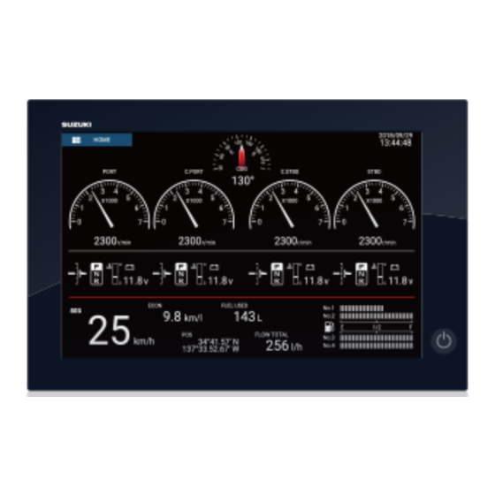
ENGINE DISPLAY Engine Display Overview With connection of outboard motor and appropriate sensors, this equipment provides two types of specialized displays: Engine display: This display provides engine information. Analog and digital displays engine speed, highway display, NAVpilot data, etc. can be shown. The display can be programmed to a full screen or 3-way split screen. -
Page 59: Engine Display
2. ENGINE DISPLAY 2.2.1 Engine display examples This section provides examples of the available engine displays, with their default con- figurations. Your displays may be different depending on your system configuration. Full screen Single engine display Dual engines display... - Page 60 2. ENGINE DISPLAY Triple engines display Quad engines display...
- Page 61 2. ENGINE DISPLAY Used Used Full 1 display Full 2 display Historical Graphs display...
- Page 62 2. ENGINE DISPLAY 3-way split screen Single engine display Dual engines display Quad engines display Triple engines display Navigation display Historical Graphs display Wind display Environment Numerical display...
- Page 63 2. ENGINE DISPLAY Numeric display Highway display NAVpilot display Tank display The tank item shows fuel level in both analog and digital formats. The analog indicator rises or lowers with fuel level and the color changes according to the percentage of fuel remaining.
-
Page 64: How To Switch Between Engine Displays
2. ENGINE DISPLAY 2.2.2 How to switch between Engine displays 3-way split screen The default display screens in the 3-way split screen are [Engines], [Navigation], [Historical Graphs], [Environment Numerical], [Wind], [Numeric], [Highway], [NAVPilot], and [Tank]. The availability of a display depends on your system configu- ration. -
Page 65: How To Edit The Engine Display
2. ENGINE DISPLAY 2.2.3 How to edit the Engine display The Engine displays are fully customizable. You can edit the displays as follows: • Remove the item from the display • Add the item to the display • Rearrange the item in the display •... - Page 66 2. ENGINE DISPLAY How to edit, remove the item in the Engine display 1. Tap the item to process to show the [Edit Instrument] pop-up menu. 2. Do one of the following depending on your objective: • Bring to front: If two items are occupying the same location, you can select one to bring to the front.
- Page 67 2. ENGINE DISPLAY • Change the graph’s plotting period and range: Tap [Plot Period] to change the time over which the graph’s data is plotted (x axis). Tap [Plot Range Value] to change the range for the data display in the graph (y axis). Note: Depending on the range and period selected, some data may be dis- played with steep peaks and troughs when converted into graph format.
- Page 68 2. ENGINE DISPLAY How to add the item to the Engine display 1. Prepare the display for editing as shown in "How to prepare for editing" on page 2- 2. Tap an unoccupied position on the display to show the [Add Instrument] pop-up menu.
-
Page 69: Fuel Management System
2. ENGINE DISPLAY How to add the Engine display Ten full size and six split screen Engine displays are preset in this equipment. If the displays do not meet your requirements, you may add custom displays as necessary. A maximum of ten each of full screen and split screen displays is available. 1. -
Page 70: Sc-33 Data Display
2. ENGINE DISPLAY How to manually enter fuel tank capacity 1. From the home screen, tap [Settings][Initial Setup]. 2. At [Total Fuel Capacity], enter your vessel’s total fuel capacity. 3. Set the flipswitch of [Manual Fuel Management] to [ON]. 4. Tap [OK] to finish. Fuel management from the Slide-out menu You can check remaining fuel and update fuel amount from the [Slide-out] menu. -
Page 71: Troll Mode
2. ENGINE DISPLAY Troll Mode 2.3.1 How to Use the Troll 1. Shift into forward or reverse gear and make sure that the throttle is fully closed (in-gear idle speed). 2. Confirmation screen to draw your attention will be displayed. 3. -
Page 72: How To Cancel The Troll Mode
2. ENGINE DISPLAY 4. Adjust the trolling speed from following display. • When you tap the [+] button, the engine speed increases by 50 r/min. • When tap the [-] button, the engine speed decreases by 50 r/min. Notes on the adjustment •... -
Page 73: Qr Code
2. ENGINE DISPLAY QR Code Acquire the engine information, then record and readout the data with SUZUKI Diag- nostic System Mobile. Acquire the engine information, then, convert to QR code and record the data. Created QR code (ex. Port engine) 2.4.1... -
Page 74: How To View Qr Code Logs
2. ENGINE DISPLAY 2.4.2 How to view QR Code logs Standard operation 1. Open the home screen, then tap the [Settings] - [Engine Setup]. 2. Swipe the Sub menus screen. 3. Tap the [View QR Code Logs]. 4. Tap selected Log. Quick operation 1. -
Page 75: Reset Data
2. ENGINE DISPLAY Reset Data [ENG TRIP TIME], [ENG TRIP DIST], [ECON AV], [FUEL USED] can be reset. Another data except above can be also reset. Standard operation 1. Open the home screen, then tap the [Settings] - [Engine Setup]. 2. - Page 76 2. ENGINE DISPLAY 5. Tap the [Insert Code]. Show the keyboard. (The keyboard displayed depends on the item selected. Some items provide only the numeric keyboard.) Enter data, then tap [] to confirm. Keyboard 6. Tap the [OK]. 2-19...
-
Page 77: Engine Alarms
2. ENGINE DISPLAY Engine Alarms Alarm Icon Status bar Caution Message (ex. Check Engine 2-3 (PORT)) If an alarm occurs, the display will display the caution message and the caution alarm icon immediately. The caution message clears when any of the Status bar are pressed on the display. -
Page 78: List Of Caution Message
Cannot switch to troll mode. Read Owner's Manual and then, re-operate to get into troll mode. The current ECM and BCM does not applicable to the troll mode system. Consult with your Suzuki Marine Dealer. 2-21... -
Page 79: Czone
2. ENGINE DISPLAY CZone The Multi-Function Display can control Power Products’ CZone equipment connected in the network. CZone is a shipboard power management system. This equipment controls [CZone Control], [CZone Modes] and [CZone Monitoring]. • CZone Control: Controls the power of individual CZone equipment. •... -
Page 80: Czone Control
2. ENGINE DISPLAY 2.8.2 CZone control Display and operations from the Engine display 1. On the home screen, tap the Engine display icon. If there is no Engine display icon, see section 1.7.1 for how to add the icon. 2. Tap the display screen, to show the following pop-up menu. 3. - Page 81 2. ENGINE DISPLAY You can customize the CZone Control, CZone Modes and CZone monitoring screens. See section 2.2.3. Customized screen (example) Display and operations from the slide-out menu 1. Open the slide-out menu. 2. Tap [CZone Control] to show the following menu. 3.
-
Page 82: Czone Modes
2. ENGINE DISPLAY 2.8.3 CZone modes Display and operations from the Engine display 1. On the home screen, tap the Engine display icon. If there is no Engine display icon, see section 1.7.1 for how to add the icon. 2. Tap the screen to show the following pop-up menu. 3. - Page 83 2. ENGINE DISPLAY You can customize the CZone Control, CZone Modes and CZone monitoring screens. See section 2.2.3. Customized screen (example) 4. Tap the X button on the title bar to close the menu. Display and operations from the data area 1.
- Page 84 2. ENGINE DISPLAY 3. Tap the display mode to add. The selected item appears at the bottom of the data area. Tide Height Speed Direction Next Tide Time 4. Tap the added item to control corresponding CZone device. Display and operations from the slide-out menu 1.
-
Page 85: Czone Monitoring
2. ENGINE DISPLAY 2.8.4 CZone monitoring Display on the Engine display 1. On the home screen, tap the Engine display icon. If there is no Engine display icon, see section 1.7.1 for how to add the icon. 2. Tap the screen to show the following pop-up menu. 3. - Page 86 2. ENGINE DISPLAY You can customize the CZone Control, CZone Modes and CZone monitoring screens. See section 2.2.3. Customized screen (example) 4. Tap the X button on the title bar to close the menu. Display and operations from the data area 1.
- Page 87 2. ENGINE DISPLAY This page is intentionally left blank. 2-30...
-
Page 88: Plotter
PLOTTER This chapter shows you how to do the following: • Use and prepare the plotter display • Set plotter related alarms • Control the track Chart Type A world map in raster chart format is included in your unit. A vector chart for the US coastline (Alaska and Hawaii included) is provided also. -
Page 89: Display Range
3. PLOTTER Display Range You can change the display range to change the amount of information shown. The selected range appears in the box at the bottom left-hand corner of the screen. Range area Range area Display range How to zoom in or out the display range Method 1: Pinch the plotter display. -
Page 90: Orientation Mode
3. PLOTTER Orientation Mode The chart can be shown in head-up or north-up orientation. Tap the orientation mode switch, [HU] or [NU], whichever is shown, at the bottom left corner to change the ori- entation mode. North Up: North is at the top of the screen. When your heading changes, the boat icon moves according to heading. -
Page 91: The Boat Icon
3. PLOTTER The Boat Icon 3.5.1 Description The boat icon (red) marks current position and moves according to your vessel’s movement. Heading line Turn direction indicator COG vector • The heading line is a straight line that runs from your position and shows the cur- rent heading. -
Page 92: Cog Vector Length
3. PLOTTER 3.5.3 COG vector length The COG vector shows estimated course and speed of your ship. The tip of the vector is the estimated position of your ship at the end of the selected predictor time or dis- tance (set on the menu). You can increase the length of the predictor to find the esti- mated position of your ship in the future on the current course and speed. -
Page 93: Boat Icon Orientation
3. PLOTTER 3.5.4 Boat icon orientation You can select the orientation of the boat icon to heading or COG. 1. Open the home screen, then tap [Settings] - [Ship & Track]. 2. Tap [Vessel Icon Orientation]. 3. Tap [Heading] or [COG]. 4. -
Page 94: Chart Information
3. PLOTTER Detailed information Tap an object to show the pop-up menu. Tap [Chart Object info] on the pop-up menu to show detailed information. 3.6.2 Chart information Tap a location on the chart not occupied by a chart object, then tap [Chart Info] on the pop-up menu. -
Page 95: How To Find The Range And Bearing Between Two Locations
3. PLOTTER How to Find the Range and Bearing Between Two Locations The [Distance] item in the slide-out menu measures the range and bearing between any two locations on your chart. Range and bearing between the two locations are dig- itally indicated on the screen. -
Page 96: Multiple Plotter Displays
3. PLOTTER Multiple Plotter Displays Three plotter displays can be shown on one screen. With three plotter displays, you can see the conditions around your ship on both short and long ranges. Also, you can see how your ship moves toward your destination from more than one angle. For ex- ample, you can show one display in 3D and the other two in 2D. -
Page 97: Cartographic Text And Objects On Vector Charts
3. PLOTTER Cartographic Text and Objects on Vector Charts This section shows you how to show or hide the cartographic objects and text infor- mation that appear on the vector charts. 3.9.1 Control visibility of text and object information in vector charts The [Settings] - [Vector Chart] menu controls the visibility of text and object informa- tion, for example, buoy names and light description. -
Page 98: Control Visibility Of Cartographic Objects In S-52 Charts
3. PLOTTER [Display Light Description]: Show or hide the light descriptions. [Display Light Sectors]: Show or hide light sectors for fixed beacons. [Display Routes]: Show or hide routes. [Display Routes Bearings]: Show or hide route bearings. [Display Soundings]: Show or hide depth soundings. [Display Soundings in Red]: Spot soundings whose depths are lower than the value selected on the [Shallower than...] menu are shown in red. - Page 99 3. PLOTTER Note: The following menu items except [Reset Default Settings] are unavailable when you select the mode other than [Custom] [Unknown Object]: Show or hide unknown objects that appear on the chart. [Chart Data Coverage]: Show or hide the geographic names and geographic objects. [Water and Seabed Features]: Show or hide the water and seabed presentation.
-
Page 100: Alarms
3. PLOTTER 3.10 Alarms The various plotter alarms alert you (with audiovisual alarms) when the conditions specified are met. These alarms are: • Anchor watch alarm • Speed alarm • Depth alarm • XTE alarm • Sea surface temperature alarm •... -
Page 101: Xte Alarm
3. PLOTTER 3.10.1 XTE alarm The XTE alarm tells you when your ship goes off course by more than the limit set (XTE alarm boundaries). Starting point Go to point Alarm setting Intended :Alarm area course 1. Turn on [XTE Alarm] in the [Alarm] menu. 2. -
Page 102: Speed Alarm
3. PLOTTER [Over] or [Under] The [Over] or [Under] alarm sounds when the temperature is over or under the set value, respectively. 1) Tap [Temperature Alarm Value] to display the software keyboard. 2) Set the value, then tap []. Go to step 3. [Within] or [Out of] The [Within] or [Out of] alarm sounds when the temperature is within or out of the temperature range set, respectively. -
Page 103: Anchor Watch Alarm
3. PLOTTER 3.10.5 Anchor watch alarm The anchor watch alarm tells you that your ship has moved a distance greater than the set value when the ship must not be moving. Alarm : Alarm area setting Your ship's position where you start the anchor watch alarm. -
Page 104: Alarms List
3. PLOTTER 3.10.8 Alarms list When an alarm is violated, you can see the name of the offending alarm on the [Alarms] list. The list stores both warning and system messages. Open the home screen, then tap [Lists] followed by [Alarms]. Active alarms are flashing and have a red vertical bar at the let margin. -
Page 105: Track Recording Interval
3. PLOTTER 3.11.3 Track recording interval Tracks are recorded at specified time or distance intervals to the internal memory of this unit. A shorter interval gives a smoother, clearly reconstructed track, however the overall distance/time that can be recorded is shorter. When the positioning data source is set to SC-30, or the internal GPS antenna, the following occurs: •... -
Page 106: Track Color
3. PLOTTER 3.11.4 Track color Track can be displayed in a single color or multiple colors. For multiple colors, you can display the track according to one of the conditions shown below. - Depth - SST Range - SST Variation - Speed - Bottom Discrimination - Depth Variation... - Page 107 3. PLOTTER 18.01 to 18.20 18.21 to 18.40 Yellow 18.41 to 18.60 Green [Speed]: Change the color of the track with speed. [Bottom Discrimination]: Change the color of the track with bottom sediment. [Depth Variation]: Change the color of the track with depth variation. The depth at the start of track recording becomes the reference depth.
-
Page 108: Track Thickness
3. PLOTTER [Depth Variation]: Set the color for each depth variation. Tap [Step 2.0 ft], then set each color. Do the same for [Step 20.0 ft], and [Step 200.0 ft]. 9. Tap X on the title bar to close the menu. On the screen 1. -
Page 109: How To Create A Route With Track Currently Being Recorded (Track Back)
3. PLOTTER 3.11.7 How to create a route with track currently being recorded (track back) You can create a route with track that is currently being recorded. This method can be useful for retracing track; for example, when you need to retrieve crab pots or the like. The route is saved to the routes list. -
Page 110: How To Delete Tracks
3. PLOTTER 3.11.8 How to delete tracks If the screen becomes full of track, you can not know which is the newer track. Delete the track you do not need. How to delete a specific part of a track You can delete a track partially. Tap the part of a track to delete. Tap [Del From Here] or [Delete Up to Here]. -
Page 111: Plotter Menu
3. PLOTTER 3.12 Plotter Menu This section describes the [Plotter] menu items, which are in the [Settings] - [Plotter] menu. [Grid Interval]: Set the distance between grid lines. The options are [Off] (no lines), [Very Small], [Small], [Medium], [Large], and [Very Large]. [Show Scale Slider]: Show or hide the scale slider. -
Page 112: Navpilot Series Auto Pilot
3. PLOTTER [Range Link]: Activate or deactivate matching the overlay with radar ranges. [Echo Color]: Tap the color for the radar echo. Depth Shading Values [Depth Shading Transparency]: Set the degree of transparency for the depth shad- ing overlay. For the menu items shown in the table, see the mentioned section. Menu item Reference [3D Display]... -
Page 113: How To Show The Navpilot Control Box In The Data Area
3. PLOTTER 3.13.2 How to show the NAVpilot control box in the data area 1. Tap [DATA] or [ROUTE] on the data area to select where to show the NAVpilot control box. 2. Tap a data box or an unoccupied area to select where to show the NAVpilot con- trol box. -
Page 114: Activecaptain
3. PLOTTER 3.14 ActiveCaptain ActiveCaptain is a community-based sailing website that contains user-generated in- formation about marinas, anchorages, marine hazards and local points of interest for sailing grounds around the world. On the Multi-Function Display you can show or hide information about the above-mentioned data. -
Page 115: How To Show Or Hide Activecaptain Items
3. PLOTTER 3.14.4 How to show or hide ActiveCaptain items Open the [Settings]-[ActiveCaptain] menu, then show or hide items in the [Only Show AC Point of Interest...], [Local Knowledge to Show...] and [Only Show Marinas With...] sections. AC Points of Interests... Only Show Marinas With... -
Page 116: My Friends (Social Network)
When the My Friends display is active, the vessels that you have registered (see paragraph 3.15.1) are marked with a symbol, as shown in the figure below. Tap the symbol to show detailed information about the vessel. Suzuki N 34°26.400’ E 135°07.104’... - Page 117 3. PLOTTER This page is intentionally left blank. 3-30...
-
Page 118: D Display, Overlays
3D DISPLAY, OVERLAYS 3D Display The 3D display has native 3D chart design that allows full time 3D presentation. This true 3D environment gives you all of the information you require with no restrictions on the information you can see. You can plan your routes, enter points, etc. like on the 2D chart. -
Page 119: How To Activate The 3D Display
4. 3D DISPLAY, OVERLAYS 4.1.1 How to activate the 3D display 1. To switch between the 2D and 3D displays, tap the 2D/3D switch at the bottom left corner on the screen or drag upward as shown below. The icon is filled in white when the 3D display is active. -
Page 120: How To Make The 3D View Clearer
4. 3D DISPLAY, OVERLAYS 4.1.2 How to make the 3D view clearer In the 3D display, some topographical features are easier to see if you use the 3D ex- aggeration feature. This feature expands both objects on the chart and the underwater vertically so that you can easily see the shape of the objects and position. -
Page 121: Overlays
4. 3D DISPLAY, OVERLAYS Overlays Five overlays are available for the plotter display: depth shading, satellite, radar, tide information, and tidal current. 4.2.1 Depth shading overlay The depth shading overlay shows the depths in different color (the default settings are red (shallow), yellow (medium) and blue (deep)). - Page 122 4. 3D DISPLAY, OVERLAYS Depth shading settings The depth shading settings are in the [Plotter] menu. [Auto Depth Shading Color Scale]: Turn automatic depth shading color scale selec- tion on or off. [Minimum Value]: Set the minimum depth range for which to show depth shading, with the software keyboard.
-
Page 123: Satellite Photo Overlay
4. 3D DISPLAY, OVERLAYS 4.2.2 Satellite photo overlay You can put the satellite photo for your area on the 2D and 3D displays. Open the [Layers] menu then turn [Satellite Photo] on or off. High resolution satellite images for the USA coastline are not provided standard, but are available at no cost (except shipping and handling). - Page 124 4. 3D DISPLAY, OVERLAYS How to switch between stand-by and TX; match overlay and radar ranges Tap the [TX] icon at the bottom right corner to set the radar in transmit or stand-by state. The icon is filled in white when the radar is transmitting; blue in stand-by. To match overlay and radar ranges, open the home screen, tap [Settings] - [Plotter], then turn on [Range Link].
-
Page 125: Tide Info Overlay
4. 3D DISPLAY, OVERLAYS 4.2.4 Tide info overlay Your system carries worldwide tide information, shown with tide icons, which you can overlay on the plotter display. The tide icon ( ) appears at the locations of tidal record- ing stations. How to display the tide info overlay Open the [Layers] menu, then tap [Tide Heights]. - Page 126 4. 3D DISPLAY, OVERLAYS How to display the tide graph • Display tide graph for a tide station: Tap a tide icon then tap the pop-up window. • Display tide graph for the tide station nearest the selected position: Tap the desired position on the chart, then tap [Info].
-
Page 127: Tidal Current Overlay
4. 3D DISPLAY, OVERLAYS 4.2.5 Tidal current overlay The tidal current overlay is made from the tidal current data received from NOAA sat- ellites, available in North America. How to display the tidal current overlay Open the [Layers] menu, then turn [Tidal Currents] on. Arrows of more than one color and size appear on the screen and are pointing in different directions. - Page 128 4. 3D DISPLAY, OVERLAYS How to display the tidal current graph Tap a tidal current icon to display the pop-up window. Tap the pop-up window to show the [Current] graph window Clock icon Time scale Tidal current speed at the selected time How to read the tidal current graph •...
- Page 129 4. 3D DISPLAY, OVERLAYS This page is intentionally left blank. 4-12...
-
Page 130: Points, Event Marks
POINTS, EVENT MARKS About Points, Event Marks In navigation terminology, a point is any location you mark on the chart plotter, radar, sounder or weather display. A point can be a fishing spot, reference point or other im- portant location. You can use a point you have entered to set as a destination. This unit has 30,000 points (including event marks, MOB marks) into which you can enter position information. -
Page 131: How To Enter A Point, Event Mark
5. POINTS, EVENT MARKS How to Enter a Point, Event Mark 5.2.1 How to enter a point (plotter and radar displays only) Method 1: Directly on-screen 1. Tap the position on the screen where to put a point. Range 2. Tap [New Point] on the pop-up menu. Bearing The default point symbol is put at the position selected. - Page 132 5. POINTS, EVENT MARKS 3. Edit the point referring to section 5.7.4. 4. Tap X on the title bar to close the menu. Method 4: Input from external equipment External equipment (fish finder, etc.) can output points to this equipment. TLL data (NMEA 0183 format) from the external equipment is output to this equipment via an NMEA data converter (IF-NMEA2K2, option).
-
Page 133: How To Display Point, Event Mark Information
5. POINTS, EVENT MARKS How to Display Point, Event Mark Information Tap a point or event mark to display its information. The information shown depends on the display in use and the object tapped. Point, event mark information (Plotter and radar displays) Event mark information (Sounder display) -
Page 134: Event Mark Comment
5. POINTS, EVENT MARKS Event Mark Comment You can automatically attach a comment to an event mark. The comment is saved to the points list, and the default comment is [None] (no comment). To apply a comment, do as follows: 1. - Page 135 5. POINTS, EVENT MARKS 2. Tap [Default Point Symbol], [Default Point Color], or [Icons Set]. [Default Point Symbol] Icons Set [Default Point Color] [Icons Set] 3. Tap required option. To change the point size, operate the slider bar (or software keyboard) for [Points Size].
-
Page 136: Default Event Mark Settings
5. POINTS, EVENT MARKS 5.5.2 Default event mark settings 1. Open the home screen, then tap [Settings] - [Points]. 2. Tap [Default Event1 Symbol], [Default Event1 Color], or [Icons Set]. [Default Event1 Symbol] Icons Set [Default Event1 Color] 3. Tap required option. To change the point size, operate the slider bar (or software keyboard) for [Points Size]. -
Page 137: Points List
5. POINTS, EVENT MARKS Points List You can check and edit all created points in the points list. The following point data is saved for each point. • Name • Location (latitude/longitude) • Color • Icon • Comment • Distance from own ship. 5.7.1 How to show the points list 1. -
Page 138: How To View And Edit Point Details
5. POINTS, EVENT MARKS The search options appear. For searches by name, an alphabet appears. If a point starts with a particular let- ter, the letter is highlighted, as shown in the example below. Points which start with a particular letter have the first letter highlighted in the search options. - Page 139 5. POINTS, EVENT MARKS 5.7.5 How to edit a point on the screen 1. Tap the point to edit to show the pop-up menu. Point editing tools 2. To change the name of the point, tap [Name] to display the software keyboard. Change the name as follows: 1) Tap the character to edit.
-
Page 140: How To Move A Point
5. POINTS, EVENT MARKS 3. To change the position, tap [Edit Pos] to display the software keyboard. Set the position referring to the instructions in step 2. Switch latitude and longitude coordinates. Position display format Select position display format from pull-down menu. 4. -
Page 141: How To Delete A Point
5. POINTS, EVENT MARKS 5.8.2 How to move a point from the points list 1. Open the home screen, then tap [Lists] 2. Tap [Points] to open the points list. 3. Tap the point to move to show the editing window. You can also edit the position of a point from the screen. -
Page 142: How To Move A Point To The Screen Center
5. POINTS, EVENT MARKS 5.10 How to Move a Point to the Screen Center You can easily place a point at the center of the plotter display from the points list. 1. Open the home screen, then tap [Lists]. 2. Tap [Points] to open the points list. 3. -
Page 143: How To Go To A Point
5. POINTS, EVENT MARKS 5.13 How to Go to a Point Tap the point (including MOB mark) to go to among the three methods shown below. • Select the point on the screen • Select a position on the screen •... -
Page 144: How To Go To A Position Selected On Screen
5. POINTS, EVENT MARKS The following occurs: • The go to point is highlighted. • A thick red dashed line and a yellow line appear. The thick red dashed line is the course to follow to get to the point. The yellow line is the shortest course from the current position to the go to point. -
Page 145: How To Go To A Point Selected From The Points List
5. POINTS, EVENT MARKS 5.13.3 How to go to a point selected from the points list 1. Open the home screen, then tap [Lists]. 2. Tap [Points] to open the points list. 3. Tap [Name], [Icon], [Color] or [Range] at the top of the list to sort the list. 4. -
Page 146: How To Display The Point Information For The Active Goto Point
5. POINTS, EVENT MARKS 5.13.5 How to display the point information for the active goto point 1. Tap the line between own ship and the goto point to show the pop-up menu. 2. Tap [Detail] to show the [Route Detail] window. 3. -
Page 147: Boundary Lines
5. POINTS, EVENT MARKS 5.15 Boundary Lines Boundary lines imported into the equipment can be shown on the display and edited as necessary. A maximum of 100 boundary lines can be shown. For how to import boundary lines, see section 10.3. Note 1: Boundary lines cannot be created on this equipment. -
Page 148: How To Delete Boundary Lines
5. POINTS, EVENT MARKS 99/100 5.15.4 How to delete boundary lines How to delete an on-screen boundary line Tap a boundary line to show the pop-up menu. Tap [Delete] to delete the line from the screen. How to delete all boundary lines 1. - Page 149 5. POINTS, EVENT MARKS 2. To change the name, tap [Name]. The software keyboard appears. Confirm entry Erase line Confirm entry Delete selected Cursor character Alphabet keyboard Close keyboard Switch to numeric Shift cursor Switch to alphabet keyboard without saving keyboard Alphabet keyboard Numeric keyboard...
-
Page 150: Routes
ROUTES What is a Route? A route is a series of route points leading to a final destination. When you follow a route, the equipment automatically switches route points and provides pertinent navi- gation data. The equipment can store a maximum of 500 routes with a maximum of 200 points per route. -
Page 151: How To Create A Route
6. ROUTES How to Create a Route 6.2.1 How to create a new route from the plotter screen 1. Tap a location on the screen for the 1st point in the route to display the pop-up menu. 2. Tap [New Route]. The flag mark appears on the selected position and the route information box appears (at the top of the screen). -
Page 152: How To Create A New Route With Points
6. ROUTES 6.2.2 How to create a new route with points You can create a route with points (including event marks) you have previously en- tered. 1. Tap a point to display the pop-up menu. 2. Tap [New Route]. The flag mark as below appears on the point. The flag mark ap- pears on the selected position and the route information box appears (at the top of the screen). -
Page 153: How To Edit A Route
6. ROUTES 6.2.3 How to create a route from the points list 1. Open the points list. 2. Tap the point to be the first point in the route then tap [Add to Route]. Repeat to add all required points. The route is drawn on the plotter screen. 3. -
Page 154: How To Delete A Point (Incl. Route Point) On A Route
6. ROUTES 3. Move the route point to the new position by dragging the route point or tapping the new position. 4. Tap [End Move] at the top right-hand corner of the screen. 6.3.3 How to delete a point (incl. route point) on a route You can delete a point on a route. -
Page 155: Routes List
6. ROUTES Routes List The created routes are stored in the routes list, where you can edit or see the route data. The list stores the following route data for each route: • Name of route • Length of route •... - Page 156 6. ROUTES 4. From the [EDITION] section, you can edit the name, from point, to point, color and comment for the route. 5. To find details about the route, tap [Detail]. Route speed Departure date adjustment button adjustment button [Route Speed] button: Change the route speed to use to follow the route. [Departure Date] button: Change the date of departure.
-
Page 157: How To Find Number Of Routes Created
6. ROUTES How to Find Number of Routes Created Open the home screen, then tap [Settings] - [General]. Find [Routes] in the [DATA US- AGE] section. In the example below, 3 routes out of 200 have been created. 99/100 How to Find a Route on the Chart You can easily find the location of a route from the routes list. -
Page 158: How To Show Or Hide All Routes
6. ROUTES How to Show or Hide All Routes All routes (including the route information box) can be shown or hidden. Open the [Layers] menu, the turn [Routes] on or off as required. Note 1: An active route cannot be hidden from the screen unless route following is stopped. -
Page 159: How To Follow A Route
6. ROUTES 6.10 How to Follow a Route Before you follow a route, make sure that the path to the route is clear. Make sure to zoom your chart to check for hazards that do not appear on a smaller scale. 6.10.1 How to follow an on-screen route 1. -
Page 160: How To Follow A Route Selected From The Routes List
6. ROUTES 6.10.2 How to follow a route selected from the routes list 1. Open the home screen, then tap [Lists] - [Routes]. 2. Tap the route to follow then tap [Goto]. 3. Tap the close button to finish. The following occurs: •... -
Page 161: How To Show The Detailed Information About A Route
6. ROUTES 6.10.4 How to show the detailed information about a route Tap a route leg of the route, then Tap [Detail] to show the [Route Detail] window. 6.11 Operations When You Follow a Route 6.11.1 How to restart navigation When you follow a route, you can re- Line 2 start the navigation to the next route... -
Page 162: Waypoint Switching Mode
6. ROUTES 6.11.5 Waypoint switching mode When you arrive to a route point, your unit automatically changes to the next route point according to the waypoint switching mode selected on the menu. [Cross Line]: Change the waypoint when the ship moves through an imaginary cross line (vertical line) that passes through the center of the destination point. -
Page 163: Xte Lines
6. ROUTES 6.11.7 XTE lines The color of the XTE line is red for the port side, green for the starboard side. You can show or hide these lines and set their distance from own ship as follows. 1. Open the home screen, then tap [Settings] - [Routes]. 2. -
Page 164: 11Steering A Route With The Navpilot
6. ROUTES 6.11.11 Steering a route with the NAVpilot The NAVpilot can be used to steer a route, from the NAVpilot control box in the data area. The figure belows shows the NAVpilot control box. See paragraph 5.13.4 for de- tails. -
Page 165: Sar Operations
6. ROUTES 6.13 SAR Operations The SAR (Search And Rescue) feature facilitates search and rescue, and MOB (Man Over Board) operations. This feature requires several installation menu changes and requires a qualified technician to make the necessary menu changes. To active this feature, contact your local dealer. -
Page 166: Laylines
6. ROUTES 6.14 Laylines A layline is the best course for route, calculated using wind speed and direction, head- ing, own ship speed and tidal currents. Note 1: Appropriate sensors for these data are required to use the layline feature. Laylines Laylines 6.14.1... -
Page 167: How To Change The Polar Wind File
6. ROUTES 6.14.3 How to change the polar wind file Your Multi-Function Display comes with a pre-installed polar wind file. This file con- tains data for sailboats, helping to improve sailing performance, by applying the data ™ to the laylines. Polar files can be downloaded from the MyTimeZero cloud service and imported to the Multi-Function Display. - Page 168 6. ROUTES [Navigate with Autopilot]: A message asks if you want to navigate with the autopilot, after setting a destination. Requires NAVpilot. Not shown otherwise. [Autopilot Step]: Controls the amount of course change set with the preset adjust- ment buttons in the NAVpilot display. Requires NAVpilot. Not shown otherwise. Preset adjustment buttons Note: The turn/menu button ( ) appears only when a NAVpilot-300 is connect-...
- Page 169 6. ROUTES This page is intentionally left blank. 6-20...
-
Page 170: Radar
RADAR This chapter provides the information necessary for radar operation, which requires a radar sensor. Note: To change the radar source, go to the Home screen, tap [Settings] - [Radar] - [Radar Source], then tap desired radar source. How to Transmit, Set the Radar in Stand-by Tap the [TX] icon at the bottom right corner of the screen to put the radar in transmit or stand-by state. -
Page 171: How To Adjust The Gain
7. RADAR How to Adjust the Gain You can adjust the gain (sensitivity) of the radar receiver. The correct setting shows some background noise on the screen. If you do not use enough gain, weak echoes are erased. If you use more gain than necessary, the background noise hides both weak and strong targets. - Page 172 7. RADAR Method 2: Radar Control data box in data area The gain can be adjusted from the data area, with the [Radar Control] box in the [RA- DAR] data box. On the box, tap the [M/A] part of the [Gain] flipswitch to switch between manual and automatic adjustment.
-
Page 173: How To Reduce The Sea Clutter
7. RADAR How to Reduce the Sea Clutter The reflected echoes from waves appear at the central part of the screen and have the name "sea clutter". The sea clut- ter increases in width as the height of waves and the height of the antenna above the water increase. -
Page 174: Range Scale
7. RADAR Range Scale The range setting controls the size of the area (in nautical miles, kilometers or statute miles) that appears on your screen. The range appears at the bottom right-hand cor- ner of the screen. How to zoom in or out the range scale The range scale can be selected two ways, as shown below. -
Page 175: How To Measure The Range And Bearing From Your Ship To A Target
7. RADAR Head-up Heading line A display without azimuth stabilization in which the line that connects the center with the top of the screen indicates your heading. Targets are shown at their measured distances and in their directions relative to your heading. North-up Targets are shown at their measured distances Heading line... -
Page 176: How To Set The Number Of The Range Rings To Show
7. RADAR 7.8.2 How to set the number of the range rings to show 1. Open the home screen, then tap [Settings] - [Radar]. 2. Tap [Rings Interval]. 3. Tap a number. [Automatic] automatically selects the number of rings according to the range scale. -
Page 177: How To Measure The Range And Bearing To An Object
7. RADAR Head-up mode Heading line North (“0”) Boat icon Bearing scale True: Bearing scale rotates according to Relative: Bearing scale is fixed and “0” is at the top of the screen. the movement of your ship. North-up mode Heading line Boat icon... -
Page 178: How To Measure The Range With The Vrm
7. RADAR 7.8.5 How to measure the range with the VRM The VRM is a dashed ring so that you can identify the VRM from the fixed range rings. Method 1: From the data area Open the data area. Tap the VRM indication in the [EBL/VRM] box. Drag the VRM or slider to set the VRM. - Page 179 7. RADAR Method 2: From the pop-up menu Tap the screen to show the pop-up menu, then tap [VRM]. Drag the VRM or slider to set the VRM. Tap [End VRM] to anchor the VRM and finish. The range to the VRM appears to the left of the slider bar.
-
Page 180: How To Measure The Bearing With The Ebl
7. RADAR 7.8.6 How to measure the bearing with the EBL Method 1: From the data area Open the data area. Tap the EBL indication in the [EBL/VRM] data box. Drag the EBL or slider to set the EBL. Tap [End EBL] to anchor the EBL and finish. The bearing of the EBL appears to the left of the slider bar and in the [EBL/VRM] data box. -
Page 181: How To Select The Ebl Reference
7. RADAR Method 2: From the pop-up menu Tap the screen to show the pop-up menu, then tap [EBL]. Drag the EBL or slider to set the EBL. Tap [End EBL] to anchor the EBL and finish. The range to the EBL ap- pears to the left of the slider bar. -
Page 182: How To Measure The Range And Bearing Between Two Targets
7. RADAR How to Measure the Range and Bearing Between Two Targets You can measure the range and bearing between any two targets with the ruler. 1. Open the slide-out menu then tap [Distance] to display the ruler, which has two drag-able circles connected with a line. -
Page 183: Heading Line
7. RADAR 7.11 Heading Line The heading line indicates your heading in all orientation modes. This line connects between your position to the out- er edge of the radar display. The line is at zero degrees on the bearing scale in the head-up mode. The orientation of the line changes in the north-up mode with the movement of your ship. -
Page 184: Echo Average
7. RADAR 7.13 Echo Average The sea clutter reduction circuit can remove wanted echoes. If this occurs, use the echo average feature. Echo average reduces the brilliance of targets within sea clutter to allow you to better discriminate targets from sea clutter. Note 1: Echo average requires heading and position data. -
Page 185: How To Activate Or Deactivate The Guard Zone
7. RADAR 4. Tap [Resize]. Drag icons appear at the corners of the guard zone. 5. Drag the icons to adjust the guard zone. Note: To create a 360 degree zone about own ship, set all four drag icons in the same direction. -
Page 186: Echo Trail
7. RADAR 3. Tap [Watchman]. 4. Tap a watchman rest interval. 5. Tap the close button to finish. 6. On the radar display, tap the screen to show the pop-up menu. Turn [Watchman] on to activate the watchman function. 7.16 Echo Trail Echo trails show the movements of radar targets relative or true to your ship in imitation afterglow, in a color different from the echo color. -
Page 187: How To Select The Echo Trail Mode (Reference)
7. RADAR 7.16.4 How to select the echo trail mode (reference) Trail movement can be set for relative or true. The relative trails show the relative movements between targets and your ship. True motion trails show the movements of targets according to the targets over-the-ground speeds and courses. True trails re- quire position and heading information. -
Page 188: How To Select Echo Trail Shading
7. RADAR 7.16.6 How to select echo trail shading The afterglow of the target trails can be shown in a single tone or gradual shading. Target Target [Single] trail [Multi] trail 1. At the home screen, select [Settings]. 2. Select the [Radar] menu. 3. -
Page 189: Echo Color
7. RADAR 7.19 Echo Color Echo color is available in colors of green, yellow or multicolor. [Multicolor] displays echoes in colors of red, yellow and green, corresponding to signal levels of strong, me- dium and weak. 1. Open the home screen, then tap [Settings] - [Radar]. 2. -
Page 190: Dual-Range Display
7. RADAR 7.21 Dual-Range Display The dual-range display scans and displays two different radar ranges at the same time, with a single antenna. There is no time delay between the two pictures and, with the magnetron radar, you have separate control of each picture. (The solid state radar has some restrictions. -
Page 191: Bird Mode
7. RADAR The no.1 screen is independent of the no.2 screen when the no.2 screen is in stand- by. However, when the no.2 screen goes to transmit state, so does the no.1 screen. No.2 No.1 screen screen No.1 No.2 No.1 No.1 screen screen... -
Page 192: Target Analyzer
7. RADAR [Rough]: Suitable in rough weather conditions where sea clutter is strong. Applies high sea clutter reduction. Weak bird echoes may be suppressed in this setting. To select the bird mode setting, tap the display to open the pop-up. Select [Bird Mode] and desired setting option, [Calm], [Moderate], [Rough], or [Off]. - Page 193 7. RADAR is only able to sense the motion directly along the radial, either towards or away from the radar, because the transverse component has no effect on the phase of the return- ing electromagnetic wave. Radial Transverse component Total velocity Radial component Radar measures the...
-
Page 194: How To Activate Or Deactivate The Target Analyzer
7. RADAR 7.23.1 How to activate or deactivate the target analyzer Turn [Target Analyzer] on or off from the pop-up menu. 7.23.2 How to emphasize rain clutter or target echoes You can emphasize rain clutter or target echoes when the target analyzer is active. Open the [Radar] menu, then set [Target Analyzer Mode] to [Rain] or [Target] as ap- propriate. -
Page 195: Connecting With Furuno Far-2Xx7/Far-15Xx Series Marine Radars
7. RADAR 7.25 Connecting With FURUNO FAR-2xx7/FAR-15xx Series Marine Radars Your Multi-Function Display can connect with the FURUNO FAR-2xx7 series and FU- RUNO FAR-15xx series Marine Radars. The following radar type and software version restrictions apply: • FAR-15xx series: Non IMO-types only with software version 01.19, or later. •... -
Page 196: Radar Menu
7. RADAR 7.26 Radar Menu This section provides the descriptions for the radar menu items not mentioned earlier. Radar Initial Setup [Antenna Rotation]: Starts or stop antenna rotation. For the serviceman. See the in- stallation manual. [Antenna Heading Align]: Compensates for error in positioning of the antenna unit at installation. - Page 197 7. RADAR [Auto Tuning]: Activate or deactivate auto tuning for the connected radar. Not avail- able (grayed out) with the radar sensor FURUNO DRS4D-NXT,DRS6A-NXT. [Tuning Source]: For dual range display, select the range to use as the manual tuning source. Not available (grayed out) with the radar sensor FURUNO DRS4DL/ DRS4DL+, DRS4D-NXT,DRS6A-NXT.
-
Page 198: How To Interpret The Radar Display
7. RADAR 7.27 How to Interpret the Radar Display 7.27.1 False echoes Echo signals can appear on the screen at positions where there is no target or disap- pear where there are targets. You can identify false targets when you understand why the false echoes appear. - Page 199 7. RADAR Sector blanking Funnels, stacks, masts, or derricks in the path of the antenna stop the radar beam. If the angle opposite the antenna is more than one or two degrees, a sector or shadow sector appears on the screen. Targets are not displayed within the sector. Wharf and its echo Radar position Wharf and its echo...
-
Page 200: Search And Rescue Transponder (Sart)
7. RADAR 7.27.2 Search and rescue transponder (SART) A ship in distress uses a radar-SART to show a series of dots on the radar display of nearby ships to indicate distress. A SART transmits when it receives a radar pulse from any X-Band (3 cm) radar within a range of approximately 8 nm. -
Page 201: Arpa Operation
7. RADAR 7.28 ARPA Operation The ARPA (Automatic Radar Plotting Aid) shows the movement of a maximum of 30 radar targets. The targets can be acquired manually or automatically. All 30 targets can be acquired manually when the ARPA acquisition area is not active. If the ARPA acquisition area is active, that total is equally divided between manual and auto acqui- sition. -
Page 202: How To Manually Acquire A Target
7. RADAR 7.28.2 How to manually acquire a target You can manually acquire a target from both the radar display and the radar display overlay. Up to 30 targets can be acquired manually. Tap the target to acquire to show the pop-up menu, then tap [Acquire]. -
Page 203: How To Display Target Data
7. RADAR This feature, when active, runs in the background immediately after the start of trans- mission. Targets are acquired in order of distance from own ship, from nearest to fur- thest. Once a target is acquired, tracking continues regardless of subsequent Doppler behavior, even if the target becomes stationary. -
Page 204: Arpa List
7. RADAR 7.28.7 ARPA list The ARPA list displays data for all ARPA targets being tracked. How to show the ARPA list To show the list, go the Home screen, then tap [Lists] - [ARPA]. The color bars at the left side of the list denote ARPA symbol status, green for tracking or lost target, red for dangerous target. -
Page 205: How To Clear Lost Targets
7. RADAR 7.28.8 How to clear lost targets Tracking of a target cannot be continued when the echo from that target becomes lost. A lost target can be tracked after it is reacquired. Lost targets can be erased individu- ally or collectively. Individual target Tap the target to display the pop-up menu, then tap [Clear] to remove the target from the screen. - Page 206 7. RADAR 7.28.10 CPA graphic display The CPA graphic display shows the CPA between own vessel and the selected ARPA (or AIS) target with a line, called the "CPA line." You can use the CPA line to see the CPA between your vessel and ARPA targets. Whenever you change your vessel’s course and speed, you can see the new positional relationship between your vessel and ARPA targets.
- Page 207 7. RADAR This page is intentionally left blank. 7-38...
-
Page 208: Fish Finder (Sounder)
FISH FINDER (SOUNDER) This chapter describes the functions of the built-in fish finder. Note: To change the fish finder source, go to the Home screen, tap [Settings] - [Sounder] - [Sounder Source], then tap desired fish finder source. How the Fish Finder Operates The fish finder calculates the distance between its transducer and underwater objects like fish, lake bottom or seabed. -
Page 209: How To Select A Display
8. FISH FINDER (SOUNDER) How to Select a Display Your fish finder has six display modes. These modes are single frequency, dual fre- quency, bottom zoom, bottom lock, A-scope, and bottom discrimination. 8.3.1 Single frequency display The single frequency display shows either the low-fre- quency or high-frequency picture on all the screen. -
Page 210: Dual Frequency Display
8. FISH FINDER (SOUNDER) 8.3.2 Dual frequency display The dual frequency display provides both low and high frequency pictures, the low fre- quency on the left half (default). Use the dual frequency display to compare the same picture with two different sounding frequencies. High frequency frequency... -
Page 211: A-Scope Display (Display Only)
8. FISH FINDER (SOUNDER) Bottom zoom display The bottom zoom display expands the bottom and the fish near the bottom according to the zoom range selected on [Zoom Range Span] in the [Settings] - [Sounder] menu. This display helps you find the density of the bottom. A short echo tail normally indi- cates a soft bottom (sand bottom, etc.). -
Page 212: Bottom Discrimination Display
1. Open the home screen, then tap [Settings] - [Sounder]. 2. Tap [Fish Finder Source]. 3. Tap [SMD12], [SMD16], [BBDS1] or [DFF1-UHD] as applicable. 4. Tap the close button to finish. 5. To activate or deactivate the bottom discrimination display, turn [Bottom] on or off... -
Page 213: Automatic Fish Finder Operation
8. FISH FINDER (SOUNDER) Automatic Fish Finder Operation Your fish finder can be adjusted automatically to let you do other tasks. 8.4.1 How the automatic fish finder operates The automatic fish finder function automatically adjusts the gain, clutter, TVG, echo offset and range. -
Page 214: How To Shift The Range
8. FISH FINDER (SOUNDER) 8.5.3 How to shift the range The basic range and range shift functions let you select the depth you can see on the screen. This function is not available when [Auto Range] is active. 1. Open the home screen, then tap [Settings] - [Sounder]. 2. -
Page 215: How To Reduce The Clutter
8. FISH FINDER (SOUNDER) Adjusting the gain from the data area 1. Tap the data area at the location where you want to display the gain controls. The [Add NavData] menu appears. 2. Tap [Sounder Gain Control] or [Multi-Sounder Gain Control] as appropriate. The selected controls appear in the data area. -
Page 216: How To Reduce Interference
8. FISH FINDER (SOUNDER) How to Reduce Interference Interference from other fish finders and electrical equipment appears on the screen as shown in the illustration. When these types of interference appear on the screen, use the interference rejector to reduce the interference. Turn off the interference rejector when there is no interference, so that you do not erase weak echoes. -
Page 217: Echo History Display
The menu item on the FURUNO DFF-3D is "[TVG]". The TVG setting method changes with the fish finder connected. Fish finder TVG setting method Internal sounder (For SMD12, SMD16), The higher the setting the greater FURUNO DFF1, DFF1-UHD, BBDS1, the distance gain. -
Page 218: Fish Finder Alarms
8. FISH FINDER (SOUNDER) 8.11 Fish Finder Alarms Two types of fish alarms release audio and visual alarms to tell you that echoes from fish are in the area you selected. These alarms are [Fish Alarm] and [Fish Alarm for Bottom Lock]. -
Page 219: How To Activate Or Deactivate An Alarm
8. FISH FINDER (SOUNDER) 8.11.2 How to activate or deactivate an alarm Fish alarm 1. Open the home screen, then tap [Settings] - [Sounder]. 2. Turn [Fish Alarm] on or off. The fish alarm can also be activated or deactivated with [Fish Alarm] on the pop-up menu. -
Page 220: Accu-Fish
8. FISH FINDER (SOUNDER) ™ 8.12 ACCU-FISH ™ ™ The ACCU-FISH feature, which requires an ACCU-FISH capable transducer or Bottom Discrimination Sounder FURUNO BBDS1 or Network Fish Finder FURUNO DFF1-UHD, calculates the length of each fish and shows a fish symbol and depth val- ue or fish length. -
Page 221: Fish Size Correction
8. FISH FINDER (SOUNDER) 5. Tap [Solid], [Striped] or [Off] (turn off fish symbol). Solid Solid Striped Striped (small) (large) (small) (large) 154 ft 237 ft 154 ft 237 ft Depth (or Fish Size) Fish size Solid Striped Large fish symbol (more than 51 cm (20.08 inch)) Small fish symbol (10 to 50 cm (3.9. -
Page 222: How To Display The Fish Information
520-5PSD, 520-5MSD, 520-PLD, 525-5PWD, 525T-PWD, 525T-BSD, 525T-LTD/12, 525T-LTD/20, 525STID-MSD, 525STID-PWD, SS60-SLTD/12, SS60-SLTD/20 1 kW 50/200-1T, 526TID-HDD ™ To use RezBoost , set the fish finder source (with [Fish Finder Source] on the [Sounder] menu) to [SMD12], [SMD16] as appropriate. 8-15... -
Page 223: White Edge
8. FISH FINDER (SOUNDER) ™ How to set RezBoost Tap the sounder display to show the pop-up menu, then scroll the menu to show [Rez- Boost]. Tap [RezBoost], then tap [Enhanced]* or [Standard]. *Not available if the transducer is manually selected or a non-compliant transducer is used. -
Page 224: Temperature Graph
8. FISH FINDER (SOUNDER) 8.15 Temperature Graph With connection of a water temperature sensor, you can plot sea surface temperature over time. Open the pop-up menu and turn on [Temperature]. The temperature graph runs across the screen from right to left, the latest temperature at the right edge. The temperature scale is at the left edge of the display. -
Page 225: Sounder Menu
8. FISH FINDER (SOUNDER) 8.16 Sounder Menu This section describes the fish finder functions not described in previous sections. Open the home screen, then tap [Settings] - [Sounder]. ACCU-FISH Info ACCU-FISH Symbols ACCU-FISH Size Correction [Day Background Color]: Select the background color for use during daylight hours. The options are [White], [Light Blue], [Black] and [Dark Blue]. - Page 226 8. FISH FINDER (SOUNDER) [Transmit Rate Manual]: Change the TX pulse repetition rate in 21 levels (21 is high- est power.). Use 20 in normal use. Lower the TX rate in shallow waters to prevent the second reflection echo. [Sounder Transmit]: Turn on or off the sounder transmission. Sounder initial setup [Zero Line Rejection]: Turn the zero line (transmission line) on or off.
- Page 227 8. FISH FINDER (SOUNDER) [External KP]: Turn on to sync with external keying pulse. (For external sounder) [Bottom Level HF (LF)]: The default bottom level setting (0) determines that two strong echoes received in sequence are bottom echoes. If the depth indication is not stable in the default setting, adjust the bottom level here.
-
Page 228: Interpreting The Display
8. FISH FINDER (SOUNDER) 8.17 Interpreting the Display Zero line The zero line (transmission line) shows the position of the transducer. The line disap- pears from the screen when the range is shifted. Zero line Range shifted Bottom echoes The strongest echoes are from the bottom, and are normally shown in reddish-brown or red. - Page 229 8. FISH FINDER (SOUNDER) Nature of a bottom The nature of a bottom is known from the intensity and length of the bottom tail. To find the nature of a bottom, use a long pulse length and normal gain. For the hard and rough bottom, the bottom echo is reddish-brown with a long tail.
- Page 230 8. FISH FINDER (SOUNDER) Density of a school of fish If two schools appear with the same color at different depths, the one in deeper water is denser because the ultrasonic wave attenuates as it propagates and the school of fish in deep water tends to be displayed in a weaker color.
- Page 231 8. FISH FINDER (SOUNDER) Surface noise When the sea is rough or the ship moves over a wake, surface noise can appear at the top of the screen. Surface noise Air bubbles in the water When the sea is rough or the ship makes a quick Ultrasonic wave turn, there can be blank spots in the bottom echo blocked by air bubbles...
-
Page 232: Multi Beam Sonar Furuno Dff-3D
MULTI BEAM SONAR FURUNO DFF-3D This chapter describes the display screens (modes) available with the Multi Beam So- nar FURUNO DFF-3D, which displays images of the underwater and the ocean floor with high precision. Four display screens are provided, multi-sounder, side scan, cross section, and 3D sounder history. - Page 233 9. MULTI BEAM SONAR FURUNO DFF-3D Home Depth scale Depth scale Port Port Downward Downward Starboard Starboard Bottom Bottom echo echo 21.0 Depth Frequency Frequency Triple beam display Side scan display From the Home screen, tap the [Side Scan] icon to show the side scan display. The side scan display shows the echoes received from the port and starboard direc- tions.
- Page 234 9. MULTI BEAM SONAR FURUNO DFF-3D Cross section display OwnShip OwnShip PORT STBD From the Home screen, tap the [Cross Section] icon to show the School of cross section display. fish The cross section display, shows Seabed seabed and underwater conditions. This multi beam sonar uses a 120°...
-
Page 235: Multi-Sounder Display Operations
9. MULTI BEAM SONAR FURUNO DFF-3D Multi-Sounder Display Operations This section covers the functions available with the multi-sounder display. For the menu items shared with the conventional fish finder, see chapter 8. To show the menu for this function, tap the screen to show the pop up menu; or from the [Home] screen, tap [Settings][Multi-Beam Sonar]. - Page 236 9. MULTI BEAM SONAR FURUNO DFF-3D 9.2.6 Availability of points and event marks registration, and go to a point For operation, see chapter 5. The table below shows function availability according to latitude/longitude, heading data presence or absence. If there is no latitude/longitude data, none of the functions below are available.
-
Page 237: Side Scan Display Operations
9. MULTI BEAM SONAR FURUNO DFF-3D Side Scan Display Operations This section covers the functions available with the side scan display. For the menu items shared with the conventional fish finder, see chapter 8. To show the menu for this function, tap the screen to show the pop up menu; or from the [Home] screen, tap [Settings][Multi-Beam Sonar]. -
Page 238: Cross Section Display Operations
9. MULTI BEAM SONAR FURUNO DFF-3D Latitude/Longitude / Heading data: YES Item Starboard Port Point registration Go to point Event mark registration Latitude/Longitude: YES, Heading data: NO Item Starboard Port Point registration Go to point Event mark registration Cross Section Display Operations This section covers the functions available with the cross section display. -
Page 239: How To Smooth Echoes (Distance)
9. MULTI BEAM SONAR FURUNO DFF-3D 9.4.4 How to smooth echoes (distance) If echoes are "disconnected" because of an undulating seabed, change the setting to [Low], [Medium] or [High] as necessary. Smoothing is done in the range direction to smooth the echo presentation. 1. -
Page 240: How To Show Or Hide The Scale Box
9. MULTI BEAM SONAR FURUNO DFF-3D 9.4.7 How to show or hide the scale box The scale box, shown at the bottom-left corner on the display, shows depth and TX frequency. You can show the box as follows. 1. Tap the cross section display to show the pop-up menu. 2. -
Page 241: 3D Sounder History Display Operations
9. MULTI BEAM SONAR FURUNO DFF-3D 3D Sounder History Display Operations This section covers the functions available with the 3D sounder history display. The 3D sounder history is able to display up to 1024 past transmissions. For the menu items shared with the conventional fish finder, see chapter 8. To show the menu for this function, tap the screen to show the pop up menu;... -
Page 242: How To Stop Advancement Of The Display
9. MULTI BEAM SONAR FURUNO DFF-3D 9.5.4 How to stop advancement of the display You can stop advancement of the history display to observe the distribution of sea floor topography and school of fish. 1. Tap the 3D sounder history display to show the pop-up menu. 2. -
Page 243: How To Use Terrain Shading
9. MULTI BEAM SONAR FURUNO DFF-3D 9.5.8 How to use terrain shading The thickness of the shading for the seabed terrain can be adjusted. 1. Select [Settings] on the home screen. 2. Select [Multibeam Sonar] - [3D Sounder History]. 3. Select [Terrain Shading]. Drag the slider bar to adjust. The default setting is 50. - Page 244 9. MULTI BEAM SONAR FURUNO DFF-3D How to set color shading Open the menu, select Multi Beam to show the menu for setting color shading. Seabed Color Classic Hue Fish Color Classic Hue Fish Monochrome Color Gray Hue Seabed Monochrome Color Gray Hue Auto Seabed Shading Auto Seabed Shading...
- Page 245 9. MULTI BEAM SONAR FURUNO DFF-3D Menu item Description Setting options [Auto Seabed Shading] Use automatic or manual seabed shading. [ON], [OFF] Tap [A] to switch between automatic and manual depth/color shading scale setting mode. Manual mode Auto mode [Minimum Value] Use the software keyboard to set the shal- 0 to 1200 (m) lowest depth to use.
- Page 246 9. MULTI BEAM SONAR FURUNO DFF-3D Menu item Description Setting options For setting single tone or single color. [Gray Hue] [Seabed Monochrome [Brown Hue] Color] [Auto Fish Shading] Use automatic or manual fish shading. [ON], [OFF] Tap [A] to switch between automatic and manual depth/color shading scale setting mode.
-
Page 247: How To Show Or Hide The Scale Box
9. MULTI BEAM SONAR FURUNO DFF-3D 9.5.10 How to show or hide the scale box The scale box, shown at the bottom left corner on the display, shows depth and TX frequency. You can show the box as follows. 1. Tap the 3D sounder history display to show the pop-up menu. 2. -
Page 248: 10. File Operations
Further, with a My Time Zero * account, you can save settings data to the cloud. The card slot at the back of the SMD12/SMD16 is exclusively for use with chart cards. * Only boundary line data can be imported. Boundary lines can be created with TIMEZERO Marine Software. -
Page 249: How To Export Points And Routes
10. FILE OPERATIONS 3. Tap [SMD], [CSV] or [GPX]. [SMD]: For Multi-Function Display [CSV]: Cannot be used. [GPX]: For use with PC plotter Note: When exporting data in GPX format, it is recommended to make a note of the data contained in the file. GPX files names do not indicate their contents. 4. -
Page 250: How To Import Points, Routes, And Boundary Lines
10. FILE OPERATIONS 10.3 How to Import Points, Routes, and Boundary Lines You can import points, routes and boundary lines to the internal memory of this unit, using a microSD card or USB flash memory. 1. Put a microSD card in either slot on the SD Card Unit. 2. -
Page 251: How To Export, Import Track
10. FILE OPERATIONS 10.4 How to Export, Import Track How to export track This unit saves up to 30,000 points of track data. If [Automatic Track Deleting] is OFF, new track points are not saved when the capacity for track points is reached. You can export all tracks to a microSD card or USB flash memory. -
Page 252: How To Backup The Equipment Settings
10. FILE OPERATIONS How to import tracks You can import the tracks stored on a media to the internal memory of this unit. Note: Imported track is transfered to each Multi-Function Display. Track cannot be shared among units in the network. 1. -
Page 253: How To Load The Equipment Settings
10. FILE OPERATIONS 10.6 How to Load the Equipment Settings You can load saved settings data from an appropriate media to this unit, and share them with the Multi-Function Display in the network. 1. Put a microSD card in either slot on the SD Card Unit. 2. -
Page 254: How To Retrieve Settings/Data From The Cloud
10. FILE OPERATIONS 10.7.2 How to retrieve settings/data from the cloud Do as follows to retrieve settings data from the cloud. 1. Open the home screen, then tap [Settings][General]. ™ 2. Tap [Login] at the SOCIAL NETWORK section and login to your TimeZero count. - Page 255 10. FILE OPERATIONS This page is intentionally left blank. 10-8...
-
Page 256: 11. Camera/Video/Fusion-Link
11. CAMERA/VIDEO/FUSION-Link The camera/video function allows you to use your unit to play back images from a vid- eo player, on-board camera, network camera, DVD player and other compatible de- vices. The image from a network camera can be seen by all Multi-Function Displays in the network, however it cannot be seen on the Multi-Function Displays. -
Page 257: Video Signal Type
11. CAMERA/VIDEO/FUSION-Link 11.2 Video Signal Type There are five types of video signals which can be connected to this equipment. • Analog signal: Images from surveillance cameras, on-board cameras and video playback. • Digital signal (IP): Images from a network camera. Note: Turn on the network camera first, then turn on the MFD. - Page 258 11. CAMERA/VIDEO/FUSION-Link Nickname: If desired you can change the name of the IP camera(s). The default names are [IP CAMERA 1], [IP CAMERA 2], [IP CAMERA 3], [IP CAMERA 4]. You can use a maximum of 20 characters. To change a name, tap [NickName] to show the software keyboard.
- Page 259 11. CAMERA/VIDEO/FUSION-Link Axis Quad Server digital signal A maximum of two Axis Quad Servers can be connected. Each server can be set in- dividually with the menus [AXIS QUAD SERVER] and [SECOND AXIS QUAD SERV- ER], respectively. Server: Turn this item on to receive the signal from the Axis Quad Server. IP Server: Enter the IP address of the server, using the software keyboard.
- Page 260 11. CAMERA/VIDEO/FUSION-Link FLIR camera Images from an infrared camera allow you to navigate easily at night or in bad weath- er. Open the home screen, then tap [Settings][Camera][FLIR Installation]. Note: To use the PTZ function of the FLIR camera with the Multi-Function Display, a setting (Nexus CGI Interface, port: 8090) is required at the FLIR camera.
-
Page 261: How To Adjust The Image Size
11. CAMERA/VIDEO/FUSION-Link 11.3.2 How to adjust the image size You can adjust the image size from the pop-up menu. 1. In the camera mode, tap the screen to show the pop-up menu. 2. Tap the camera display to adjust. For multiple camera installation, Image size see section 11.3.3. -
Page 262: How To Adjust The Video Image
11. CAMERA/VIDEO/FUSION-Link 11.3.4 How to adjust the video image Tap the screen to show the pop-up menu. Tap [Contrast] or [Brilliance] on the pop-up, then drag the slider to adjust. Current setting (ex. Contrast) Drag slider (or tap bar, +, - icons) Tap screen to show pop-up menu. -
Page 263: Touch Control On The Camera Display
11. CAMERA/VIDEO/FUSION-Link 11.6 Touch Control on the Camera Display Operations available with connection of an analog camera, Axis Server 241Q Operation Function Opens the pop-up menu. Operations available with connection of a FLIR camera Operation Function Points camera to direction tapped. -
Page 264: Fusion-Link
11. CAMERA/VIDEO/FUSION-Link 11.7 FUSION-Link FUSION-Link allows compatible Multi-Function Display to interface and achieve con- trol of specialized FUSION marine entertainment equipment. 11.7.1 How to access the FUSION screen and controls The FUSION controls can be accessed 3-ways: • From the home screen (full screen) •... - Page 265 11. CAMERA/VIDEO/FUSION-Link Drag bar to adjust squelch. Tap to select CH16. Channel selection mode Hide or show menu. Lower volume. Select channel. Tap: Switch channel selection mode between Mute/unmute. preset and manual. Long tap: After selecting channel in manual mode, long tap to register the channel as preset channel.
-
Page 266: Fusion Settings
11. CAMERA/VIDEO/FUSION-Link Tap to go to full screen FUSION display. Tap to hide bar. For iPod For VHF 11.7.2 FUSION settings Open the Home screen, tap [Initial Setup], then scroll down to find the [FUSION] sec- tion. Set the [FUSION] items referring to the descriptions shown below. [Connect to Fusion]: Connects to your FUSION equipment. - Page 267 11. CAMERA/VIDEO/FUSION-Link This page is intentionally left blank. 11-12...
-
Page 268: Sirius/Xm Satellite Weather Receiver (Bbwx3) Operations
U.S. Information provided by the Sirius Marine Weather service is advisory in nature. You, the customer, agree to release SUZUKI MOTOR CORPORATION. Sirius Satellite Ra- dio Inc., Navcast Inc. and WSI Corporation from any problems that occur from this ser- vice. -
Page 269: Navcenter Weather
12. SIRIUS/XM SATELLITE WEATHER RECEIVER (BBWX3) OPERATIONS agreement and agree to all the conditions of the subscription. If you do not have the subscription agreement, got to www.sirius.com/marineweatheragreement or call 1- 800-869-5480 to have a copy sent to you. You can put a point on the weather display. Tap the screen where to put a point, then tap [New Point] on the pop-up menu. - Page 270 12. SIRIUS/XM SATELLITE WEATHER RECEIVER (BBWX3) OPERATIONS 4. Tap [Tidal Step]. 5. Tap the update interval (which determines how often tidal data are captured) for the tide icon. 6. Tap [Duration of Animation]. 7. Tap the update interval for the animation. The larger the time, the slower the ani- mation moves.
-
Page 271: How To Download The Navcenter Weather Data
12. SIRIUS/XM SATELLITE WEATHER RECEIVER (BBWX3) OPERATIONS 12.2.2 How to download the NavCenter weather data 1. Open the home screen, then tap [Settings] - [General]. 2. Tap [Wireless LAN Settings]. 3. Turn on [Wireless]. 4. After the internet connection is established, tap the close button to exit. 5. -
Page 272: How To Display The Navcenter Data
12. SIRIUS/XM SATELLITE WEATHER RECEIVER (BBWX3) OPERATIONS 11. Open the weather display, then tap the screen to show the pop-up menu. Tap [Get Latest Wx]. The notification bar at the top of the screen flashes "Weather Update in Progress" during the downloading. If the downloading was successful, the message " DOWN- LOAD SUCCEEDED"... -
Page 273: How To Load A Weather File
12. SIRIUS/XM SATELLITE WEATHER RECEIVER (BBWX3) OPERATIONS 12.2.4 How to load a weather file You can load a weather file saved on a microSD card or USB flash memory. 1. Put a formatted microSD card in either slot on the SD Card Unit. 2. -
Page 274: How To Display The Sirius Data
12. SIRIUS/XM SATELLITE WEATHER RECEIVER (BBWX3) OPERATIONS 12.3.2 How to display the Sirius data [Wx Radar] (Weather radar) NOWRAD and Canadian weather radar information are put on top of your chart (see paragraph 12.3.1). To display the weather radar, turn on [Wx Radar] from the layer menu. -
Page 275: Weather Icons (Sirius Weather)
12. SIRIUS/XM SATELLITE WEATHER RECEIVER (BBWX3) OPERATIONS 12.4 Weather Icons (Sirius Weather) The table below shows the weather icons that appear on the Sirius marine weather display. You can show or hide these icons from the pop-up menu, with [Wx Data]. Icon Meaning Storm cast... -
Page 276: Weather Data (Navcenter Or Sirius)
12. SIRIUS/XM SATELLITE WEATHER RECEIVER (BBWX3) OPERATIONS 12.5 Weather Data (NavCenter or Sirius) The table below shows the weather data available for displaying according to weather data server (NavCenter or Sirius). Items NavCenter Sirius Item NavCenter Sirius Wind Currents Waves Altimetry Plankton Cloud... - Page 277 12. SIRIUS/XM SATELLITE WEATHER RECEIVER (BBWX3) OPERATIONS [Rain/Snow]: The rain/snow fore- cast displays rain/snow images. 0.1 mm/hour of rainfall/snowfall (mini- mum) is displayed in green, 5 mm/ hour (maximum) in dark violet. 4,979 [Air Temp]: The air temp forecast displays the air temperature by col- or.
- Page 278 12. SIRIUS/XM SATELLITE WEATHER RECEIVER (BBWX3) OPERATIONS Pressure icon Meaning Trough Squall line Dry line Isobars 1010 [500mb]: The 500mb forecast dis- plays the contour lines over 500 mb. 4,898 [SST] (Sea surface tempera- ture): This data layer shows the temperature of the sea surface in shades.
-
Page 279: Sirius Weather Diagnostics
12. SIRIUS/XM SATELLITE WEATHER RECEIVER (BBWX3) OPERATIONS [Currents]: The current forecast dis- plays the tidal current speed and di- rection by blue arrow. The darker the blue, the faster the current speed (0 to 2 kn). 1,621 [Altimetry]: The altimetry forecast displays the sea height anomalies by color. -
Page 280: Sirius Satellite Radio
12. SIRIUS/XM SATELLITE WEATHER RECEIVER (BBWX3) OPERATIONS 12.7 Sirius Satellite Radio The Sirius satellite radio provides round-the-clock, 100% commercial-free music from every genre plus sports, news, talk and comedy. 12.7.1 How to enable the radio Method 1: From the home screen Go to the home screen and tap the Sirius icon to show the full screen Sirius radio con- trols. -
Page 281: How To Operate The Radio Controls
12. SIRIUS/XM SATELLITE WEATHER RECEIVER (BBWX3) OPERATIONS 12.7.2 How to operate the radio controls Full screen controls Channel, music genre Signal strength Sound setting Title, artist Preset channels Raise Select Select volume. CAT. channel. Mute, unmute. Lower volume. Audio control bar controls Preset channels Artist, title Channel,... -
Page 282: Radio Diagnostics
12. SIRIUS/XM SATELLITE WEATHER RECEIVER (BBWX3) OPERATIONS 12.7.3 Radio diagnostics Your Sirius XM satellite radio can be checked for proper operation as shown below. This test is intended for the service technician. 1. From the home screen, tap [Settings][Initial Setup] to show the [Initial Setup] menu. - Page 283 12. SIRIUS/XM SATELLITE WEATHER RECEIVER (BBWX3) OPERATIONS This page is intentionally left blank. 12-16...
-
Page 284: 13. Ais, Dsc Message
13. AIS, DSC MESSAGE 13.1 What is AIS? AIS (Automatic Identification System) is a system that continuously transmits the iden- tification and position of your ship to AIS-equipped ships within VHF range. All such ships also receive data from other AIS-equipped ships and display their positions and other relevant information. - Page 285 13. AIS, DSC MESSAGE Target Symbol Description type Lost AIS An AIS target becomes a lost target target if a signal is not received from the AIS target for x* min- utes. The lost target symbol is erased if a signal is not re- Color - AIS target: Blue for the Class A AIS ceived for an additional x* min-...
-
Page 286: Proximity Ais Target Alarm
13. AIS, DSC MESSAGE 13.4 Proximity AIS Target Alarm The proximity AIS target alarm alerts you when an AIS target is within the distance you specify, and is applicable to both displayed and not displayed targets. When an AIS target is within the distance set, the alarm indication "Proximity AIS Alarm" flashes in the status bar and the audio alarm sounds. -
Page 287: How To Hide Ais Targets
13. AIS, DSC MESSAGE 13.6 How to Hide AIS Targets You can hide the AIS symbols that are beyond the distance you set here. 1. Open the home screen, then tap [Settings] - [Targets]. 2. Tap [Hide AIS Targets Farther than...]. 3. -
Page 288: How To Display Ais Target Data
Tap an AIS target (plotter or radar display) to display the simple information in the pop- up menu. For detailed information, tap the target, then tap [Info] on the pop-up menu to show the [Target Info] window. Name SUZUKI MMSI 124365890 GALE WARNING 27.16N 82.40W 342.0°... -
Page 289: 13.10 Ais List
13. AIS, DSC MESSAGE 13.10 AIS List The AIS list provides information about the AIS targets you are receiving navigation data from. How to open the AIS list Open the home screen, then tap [Lists] and [AIS]. The vertical bar at the right side of the list is colored according to that vessel’s AIS tran- sponder type or vessel’s status. -
Page 290: 13.11 When An Ais Sart Is Received
How to display the detailed information for an AIS target Tap the AIS target on the AIS list then tap [Detail]. The name of the AIS is shown in the title bar and navigation data appears in the [TARGET INFO] section. SUZUKI FURUNO FURUNO... -
Page 291: 13.12 Cpa/Tcpa Alarm
13. AIS, DSC MESSAGE 13.12 CPA/TCPA Alarm This alarm helps you keep your ship away from collision by warning of targets on a collision course. The ARPA continuously monitors the predicted range at the Closest Point of Approach (CPA) and predicted time to CPA (TCPA) of each tracked target. When both the predicted CPA and TCPA are less than their set values, the target sym- bol turns red, the alarm sounds and the message "CPA/TCPA Alarm"... -
Page 292: How To Register An Ais Or Dsc Target To The Buddies List
13. AIS, DSC MESSAGE 13.13 How to Register an AIS or DSC Target to the Buddies List The buddies list provides a quick reference to ships’ MMSI and nickname. For exam- ple, you might want to enter the MMSI and nickname of partner ships or ships that of- ten operate in your area. -
Page 293: 13.14 Cpa Graphic Display
13. AIS, DSC MESSAGE 13.14 CPA Graphic Display The CPA graphic display, which requires own position and heading data, draws a line between own ship position and the selected AIS target. This feature lets you monitor an AIS target’s heading and speed changes. The display is useful as an anti-collision aid, especially in congested waters. - Page 294 13. AIS, DSC MESSAGE 13.15 AIS Transponder FA-30, FA-50 The FURUNO AIS Transponder FA-30 (or FA-50) installs in the network and can be controlled from a Multi-Function Display. To access the menu for the transponder, do as shown below. See the respective operator’s manual for details. 1.
-
Page 295: 13.16 Dsc Message Information
Tap a DSC marker to display the simple information (position, MMSI no. of the ship that transmitted a DSC message, etc.). To get detailed information, tap a DSC marker, then tap [Info] on the pop-up menu. SUZUKI 5.992 NM TCPA 41’30s... -
Page 296: 4The Dsc List
13. AIS, DSC MESSAGE 13.16.4 The DSC list The DSC list shows the name, MMSI, range, bearing, CPA and TCPA of vessels from which you have received a DSC message. 1. Open the home screen, then tap [Lists] - [DSC]. List sort buttons 2. - Page 297 13. AIS, DSC MESSAGE This page is intentionally left blank. 13-14...
-
Page 298: 14. Other Functions
14. OTHER FUNCTIONS Once you have become acquainted with your equipment, you can set it according to your needs. You can change system configuration, change how the equipment oper- ates and displays information, etc. 14.1 General Menu The [General] menu contains items that once preset do not require frequent adjust- ment. - Page 299 14. OTHER FUNCTIONS Menu item Function Options [Move Tool on Enable the "move" function with long-push of an [ON], [OFF] Long Push] object. Applicable to points (excluding Sounder), temporary waypoints, route waypoints, guard zone, EBL, VRM and external equipment menu icon ( [User Interface Select the timeout for the home icon on the [Lay-...
-
Page 300: Units Menu
14. OTHER FUNCTIONS Menu item Function Options [Check for Soft- Update the software. See section 14.5. ware Update] [Reset Default Restore default settings for the items of the [Gen- Settings] eral] menu. * In the demo mode, plotter display, you can relocate the boat icon to the location tapped. -
Page 301: Initial Setup Menu
14. OTHER FUNCTIONS Menu item Options [Atmospheric Pressure] [HectoPascal], [Millibar], [Millimeter of Mercury], [Inch of Mercury] [Oil Pressure] [KiloPascal], [Bar], [Pound per Square Inch] [Volume] [Gallon] (Gallon & Gallon/Hour), [Litre] (Litre & Litre/Hour) [Reset Default Settings] Restore default settings for the [Units] menu. 14.3 Initial Setup Menu The [Initial Setup] menu, which is mainly for use by the installer of the equipment, sets... - Page 302 14. OTHER FUNCTIONS INSTRUMENTS SETUP section Menu item Description Options (setting range) See "Engine & Tank Automatic Setup" below. [Engine & Tank Automatic Setup] See "Engine & Tank Automatic Setup" on the next page. [Engine & Tank Manual Setup] [Graphic Instruments See "Graphic Instruments Setup"...
- Page 303 14. OTHER FUNCTIONS [Graphic Instruments Setup] - [Propulsion Engine] Menu Item Description Options (setting range) [Max. RPM] Set the maximum rpm of your engine to 1 rpm to 20,000 rpm show on the RPM display. [Red Zone Oil Pressure] Set the starting value for the red zone area 0 kPa to 998 kPa of the oil pressure meter.
- Page 304 14. OTHER FUNCTIONS IF-NMEAFI SETUP section Menu item Description Options (setting range) [Select IF] Select [IF-NMEAFI] to set the analog data that is input from the IF-NMEAFI. [Category] Select the category for the analog sensor to [Wind], [ST800_850], [Fuel], set. [FreshWater], [WasteWater], [LiveWell], [Oil], [BlackWater] [Resistance Full]...
- Page 305 14. OTHER FUNCTIONS Menu item Description Options (setting range) [Create New QR Code] To create new QR Code. [View QR Code Logs] To read out the recorded data . [Reset Data...] To reset the data. [Installation...] Menu for qualified technician only. NETWORK SENSOR SETUP section The [NETWORK SENSOR SETUP] section allows you to set up compatible FURUNO NMEA2000 sensors.
- Page 306 14. OTHER FUNCTIONS BROWSER INSTALLATION section Menu item Description Option (setting range) [FAX30 Browser] Show the Facsimile Receiver FURUNO FAX-30 display. [FA30 Browser] Show the AIS Receiver FURUNO FA-30 display. [FA50 Browser] Show the AIS Receiver FURUNO FA-50 display. Others menu items Menu item Description Option (setting range)
-
Page 307: Facsimile Receiver Furuno Fax-30
14. OTHER FUNCTIONS 14.4 Facsimile Receiver FURUNO FAX-30 The FURUNO Facsimile Receiver FAX-30 installs in the Multi-Function Display net- work and can be controlled from a Multi-Function Display. Below are the steps to start fax operation. 1. Connect the FAX-30 to the Multi-Function Display network. 2. -
Page 308: How To Manage Your Charts
14. OTHER FUNCTIONS 14.5 How to Manage Your Charts The Multi-Function Display uses the same Mapmedia charts. Even though Multi-Func- tion Display is a master-less system in networking, for charts one Multi-Function Dis- play should be set as Chart Master to share the System ID, which will be necessary to obtain a chart unlock code from Mapmedia. -
Page 309: How To Hide Unnecessary Charts On The Chart Catalog List
Free (USA and NOAA) and for-fee Multi-Function Display compatible charts are pro- vided by SUZUKI and Mapmedia. Go to the URLs shown below to download chart da- Download the chart file to your desktop. Unzip the file, then copy it to the root of a mi- croSD card. -
Page 310: Maintenance, Troubleshooting
15. MAINTENANCE, TROUBLE- SHOOTING This chapter has information about maintenance and troubleshooting that the user can follow to care for the equipment. NOTICE WARNING Do not apply paint, anti-corrosive ELECTRICAL SHOCK HAZARD Do not open the equipment. sealant or contact spray to plastic parts or equipment coating. -
Page 311: Fuse Replacement
The life of the LCD for the SMD16 is approximately 18,000 hours; for the SMD12 it is approximately 25,000 hours. The actual life of the LCD is affected by the operating en- vironment (temperature, humidity, etc.). -
Page 312: Troubleshooting
MFB52A- 000-175-998-10 Approx. For SMD12, 12HA-002 21,000 SMD16 hours 15.4 Troubleshooting This section provides simple troubleshooting procedures that the user can follow to re- store normal operation. If you cannot restore normal operation, do not check inside the unit. Have a qualified technician check the equipment. -
Page 313: Radar Troubleshooting
15. MAINTENANCE, TROUBLESHOOTING 15.4.2 Radar troubleshooting Problem Remedy The radar cannot transmit. • Tap the [TX] icon again. (The icon is filled in white when the ra- dar is in transmit state.) • Check that the antenna cable is tightly fastened. •... - Page 314 15. MAINTENANCE, TROUBLESHOOTING Problem Remedy Noise or interference shows on • Make sure the transducer cable is not near the engine. the display. • Check the ground for tight connection, corrosion. • Check if another fish finder near your boat has the same fre- quency as your fish finder.
- Page 315 15. MAINTENANCE, TROUBLESHOOTING This page is intentionally left blank. 15-6...
-
Page 316: Appendix 1 Menu Tree
APPENDIX 1 MENU TREE Settings menu Bold italic: Default setting General Function Gesture (None, Screen Capture, Event, Home, Settings, Lists, Tide, Fusion* , Fusion bar* Move Tool on Long Push (OFF, Connect to the Internet (Never, At Startup, When Necessary) Wireless LAN Settings (Open the dialog box for Wireless LAN settings.) User Interface Auto-Hide (0’03s, 0’05s, 0’10 s, 0’15s) Instrument Theme (White, Black) - Page 317 APPENDIX 1 MENU TREE Routes Default Route Color (Red, Blue, Green, Yellow, Magenta, Orange, Cyan, Black) Route Thickness (1 - 10 or 2 - 2) (1 - 10=2D mode, 2 - 11=3D mode) Routes Density (Low, Medium, Full) Navigate with Autopilot* (ON, OFF) *Requires FURUNO NAVpilot.
- Page 318 APPENDIX 1 MENU TREE Plotter Grid Interval (Off, Very Small, Small, Medium, Large, Very Large) Show Scale Slider (OFF, ON) Tide/Current Icons Size (50 - 150(%), 100) NavData Transparency (0 - 80(%), 10) PhotoFusion Transparency (0 - 80(%), 15) Tide Range for PhotoFusion (0.0 - 60(ft), 0) Tidal Currents Transparency (0 - 80(%), 25) Radar Transparency (0 - 80(%), 20) Range Link (ON, OFF)
- Page 319 APPENDIX 1 MENU TREE S-52 S-52 Vector Chart Display Mode (Custom, Base, Standard, Other, Fishing) Display Unknown Object (ON, OFF) Chart Data Coverage (ON, OFF) Water and Seabed Features (ON, OFF) Traffic Routes (ON, OFF) Information Areas (ON, OFF) Buoys & Beacons (ON, OFF) Lights (ON, OFF) Fog Signals (ON, OFF) Radar (ON, OFF)
- Page 320 APPENDIX 1 MENU TREE Weather Load Weather File (Open the dialog box to select the weather file to load.) Weather Data Server (NavCenter, Sirius) Sirius Weather Radar (USNowRadar, CanadianRadar) Zone Forecast (BBWX3 only) Marine Warnings (BBWX3 only) Tropical Infos (BBWX3 only) Sirius Diagnostic (BBWX3 only) Tidal Step (5’00s, 10’00s, 15’00s, 20’00s, 30’00s, 1h00’, 2h00’, 3h00’, 6h00’, 12h00’) Duration of Animation (0’05s, 0’10s, 0’15s, 0’20s, 0’30s, 0’45 s, 1’00s, 2’00s, 3’00s)
- Page 321 APPENDIX 1 MENU TREE Radar Radar Source (Select the antenna host name.) Day Background Color (Black, Dark Blue, White) Night Background Color (Black, Dark Blue) Echo Color (Multicolor, Green, Yellow) Rings Interval (Auto, 1, 2, 3, 4, 5, 6, 7, 8, 9) Show Range Slider (ON, OFF) Own Ship Icon (ON, OFF) Bearing Scale Mode (Relative, True)
- Page 322 APPENDIX 1 MENU TREE Sounder Fish Finder Source (SMD, network sounder name if connected) Day Background Color (White, Light Blue, Black, Dark Blue) Night Background Color (Black, Dark Blue) Echo Color Levels (8 Colors, 16 Colors, 64 Colors) Show Range Slider (ON, OFF) A-Scope Peak Hold (ON, OFF) Zoom Reference Lines (ON, OFF) Smoothing (ON, OFF)
- Page 323 APPENDIX 1 MENU TREE Multi- Day Background Color (White, Light Blue, Black, Blue) beam Night Background Color (Black, Dark Blue) Sonar Bottom Range Shift Area (15~85(%); 50) Transmit Rate Auto (OFF, ON) Transmit Rate Manual (0~21; 20) Sounder Transmit (OFF, ON) Multi-Sounder A-Scope Peak Hold (OFF, ON)
- Page 324 APPENDIX 1 MENU TREE Fish Finder Alarms Fish Alarm (OFF, ON) Range Minimum Value (0~1200; 0m) Range Maximum Value (0~1200; 3m) Fish Alarm Level (Low, Medium, High) Initial Setup External Transducer Draft (0~99.9; 0) Salt Water (OFF, ON) Transducer Setup (Show the menu for setting up the transducer) Transmission Power Auto (OFF, ON) Transmission Power (0~10;...
- Page 325 APPENDIX 1 MENU TREE Files Export File Format (SMD, CSV , GPX) : Not used. Import Points & Routes (Open the dialog box for importing points and routes.) Export All Points & Routes (Open the dialog box for exporting all points and routes.) Import Tracks (Open the dialog box for importing tracks.) Export Tracks (Open the dialog box for exporting tracks.) (Convert Old Data Format)
- Page 326 APPENDIX 1 MENU TREE Camera HDMI HDMI Input (ON, OFF) Touch Output (ON, OFF) HCDP (ON, OFF) ANALOG CAMERA 1~2 Connected (ON, OFF) NickName (Camera 1) IP CAMERA 1~4 NickName (IP CAMERA1) IP Camera (IP address) PTZ Control (ON, OFF) AXIS QUAD SERVER Server (ON,...
- Page 327 APPENDIX 1 MENU TREE INSTRUMENTS SETUP Engine & Tank Automatic Setup Engine & Tank Manual Setup Graphic Instruments Setup Maximum Boat Speed Maximum Wind Speed DEPTH Minimum Depth Maximum Depth SEA SURFACE TEMPERATURE Minimum Sea Surface Temperature Maximum Sea Surface Temperature PROPULSION ENGINE Max.
- Page 328 APPENDIX 1 MENU TREE NETWORK SENSOR SETUP (Shows compatible FURUNO devices.) CALIBRATION Heading Speed Through Water Wind Speed Wind Angle Sea Surface Temperature DATA DAMPING COG & SOG Heading Speed Through Water Wind Speed & Angle Rate of Turn FUSION Connect to Fusion Fusion Auto Volume Minimum Speed...
-
Page 329: Appendix 2 Radio Regulatory Information
APPENDIX 2 RADIO REGULATORY INFORMATION Wireless Interoperability This product is designed to be interoperable with any wireless LAN product that is based on direct sequence spread spectrum (DSSS) and orthogonal frequency division multiplexing (OFDM) radio technology and to comply with the following standards. •... - Page 330 APPENDIX 2 RADIO REGULATORY INFORMATION USA-Federal Communications Commission (FCC) This device complies with part 15 of the FCC Rules. Operation is subject to the following two conditions: (1) This device may not cause harmful interference, and (2) This device must accept any interference received, including interference that may cause undesired operation.
-
Page 331: Specifications
SMD16 15.6-inch full-wide TFT color LCD, 1366 x 768(FWXGA) Brightness 1300 cd/m typical (SMD12), 1000 cd/m typical (SMD16) Display colors 16,770,000 colors (plotter), 64 colors (echo), 16 colors (radar) PLOTTER FUNCTION Display mode Course plot, NAV data (includes instrument and engine data) - Page 332 SMD12/16 Notification DSC receiving, Waypoint crossing, End of route, AIS target count, NAVpilot engagement (NAVpilot series required) INTERFACE Number of port 1 port, Ethernet 100Base-TX NMEA2000 1 port (LEN=1), external power input required 1 port, USB2.0 Video output 1 port, HDMI (720 p) Video input 2 ports, NTSC/PAL SD card slot...
-
Page 333: Index
INDEX Numerics anchor watch..........3-16 audio alarm silencing ......3-13 2D/3D switch ..........4-2 3D display audio alarm type........3-16 aural alarm on/off ........3-16 activating ..........4-2 bottom lock fish alarm ......8-11 description..........4-1 CPA/TCPA ........7-36 13-8 exaggeration ..........4-3 depth ............3-14 3D sounder history display fish............8-11 echo detection level .......9-11 example............9-3... - Page 334 INDEX Boundary lines deleting data box from......1-22 data display ........... 5-18 description ..........1-20 editing............ 5-19 order of data .......... 1-20 erasing ..........5-19 transparency.......... 1-22 showing, hiding ........5-18 Depth alarm..........3-14 Buddies list..........13-9 Depth measurement........8-9 Depth shading overlay description ..........
- Page 335 INDEX Event mark introduction..........1-13 entering on plotter display ......5-3 Hue............1-12 info (plotter) ..........5-4 Importing Exporting boundary lines 10-2 10-3 10-4 10-5 10-6 points............10-2 12-6 routes .............10-2 points............10-3 track ............10-5 routes .............10-3 External KP ..........8-20 track ............10-4 Initial setup menu ........14-4 False echoes Interference fish finder..........8-24...
- Page 336 INDEX Overlays Range rings depth shading.......... 4-4 bearing mode .......... 7-7 radar ............4-6 description ..........7-6 tidal current ........... 4-10 interval............. 7-7 tide info............ 4-8 Range shift (fish finder) ......8-7 Own ship icon (radar)......7-19 Remote Control Unit (MCU-002) ....1-5 Remote Control Unit (MCU-004) description ..........
- Page 337 SST alarm ..........3-14 TX/Standby switch ........7-1 Stand-by (radar) .........7-1 STC (fish finder) ........8-20 Units menu ..........14-3 SUZUKI Outboard Alarms......2-20 How to open the menu ......2-20 Vector charts text and objects....3-10 List of Caution message......2-21 Viewpoint position System configuration ......... xvi (3D sounder history display) ....9-10...
- Page 338 INDEX Weather display advanced Wx data ........ 12-7 animation radar ........12-7 introduction..........12-1 NavCenter data display ......12-5 NavCenter data download..... 12-4 NavCenter weather file......12-6 NavCenter weather setup ..... 12-2 selecting ..........12-2 Sirius ............. 12-6 Wx radar..........12-7 Wireless LAN connect to existing ........
Need help?
Do you have a question about the SMD16 and is the answer not in the manual?
Questions and answers