
Related Manuals for Optical Systems Design OSD2524


Summary of Contents for Optical Systems Design OSD2524
-
Page 1: Index
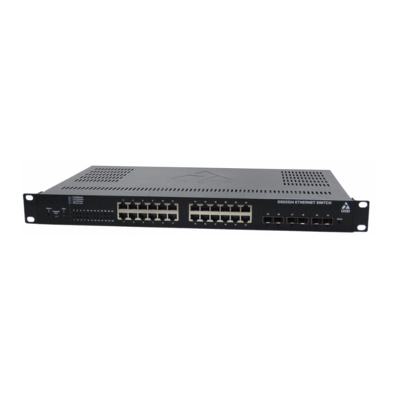
User Manual OSD2524 MANAGED 20 x 10/100/1000BASE-T (RJ45), 4 x COMBO RJ45/SFP & 2 x 1G (SFP) ETHERNET SWITCH... -
Page 3: Table Of Contents
OPTICAL SYSTEMS DESIGN INDEX 1 PRODUCT DESCRIPTION ..................... 8 FUNCTIONAL DESCRIPTION ....................8 QUICK START GUIDE ......................10 OSD2524 FRONT AND REAR PANELS ................10 ....................11 OWER UPPLY ONNECTIONS LED I ........................12 NDICATORS SFP C ..................... 13 ITTING... - Page 4 ETHERNET PROTECTION SWITCHING ............... 176 MAINTENANCE ENTITY POINT ..................178 ETHERNET RING PROTECTION SWITCHING ............. 180 MAC ADDRESS TABLE CONFIGURATION ..............183 ......................183 GING ONFIGURATION MAC T ......................184 ABLE EARNING DOC ID: 10120001 PAGE 4 OSD2524 OPERATOR MANUAL...
- Page 5 ECEIVE AND RANSMIT OUNTERS ................276 ECEIVE AND RANSMIT UEUE OUNTERS ....................276 ECEIVE RROR OUNTERS ....................276 RANSMIT RROR OUNTERS LINK OAM .......................... 278 ..................278 ECEIVE OTAL AND RANSMIT OTAL DOC ID: 10120001 PAGE 5 OSD2524 OPERATOR MANUAL...
- Page 6 LLDP ........................... 362 LLDP N EEE I ..................368 EIGHBORS NFORMATION ....................... 370 LOBAL OUNTERS ......................... 371 OCAL OUNTERS ETHERNET SERVICES ..................... 372 PTP ............................374 PTP E ..................374 XTERNAL LOCK ESCRIPTION DOC ID: 10120001 PAGE 6 OSD2524 OPERATOR MANUAL...
- Page 7 FIGURE 12: OSD2524DC POWER CONNECTION ................23 FIGURE 13: FITTING/REMOVING SFP CONNECTORS ..............25 TABLE 1: DC POWER CONNECTION....................11 TABLE 2: LED FUNCTION ......................... 12 TABLE 3: DC POWER CONNECTION....................23 TABLE 4: LED FUNCTION ......................... 25 DOC ID: 10120001 PAGE 7 OSD2524 OPERATOR MANUAL...
-
Page 8: Product Description
1 PRODUCT DESCRIPTION This manual describes how to install and setup the OSD2524 Managed Ethernet Switch. To get the most out of this manual, the user should have an understanding of Ethernet networking concepts. This manual is in two parts –... - Page 9 ∆ RFC 1213 MIB II ∆ RFC 3621 LLDP-MED power ∆ RFC 3635 Ethernet-like MIB ∆ RFC 4188 Bridge MIB ∆ Private MIB framework ∆ IEEE 802.1 MSTP MIB ∆ IEEE802.1AB LLDP DOC ID: 10120001 PAGE 9 OSD2524 OPERATOR MANUAL...
-
Page 10: Quick Start Guide
OPTICAL SYSTEMS DESIGN 3 QUICK START GUIDE OSD2524 FRONT AND REAR PANELS 1 2 3 4 FIGURE 1: FRONT PANEL Board Status LED USB Console Port View LED Mode Button View Mode LEDs Indicators Port Status LEDs RJ45 Copper Ports... -
Page 11: Power Supply Connections
Dual Redundant DC Power Version Connect the dual redundant power to the 4-way terminal block located on the rear of the unit. The OSD2524 DC version requires external +10 to +36V @ 40VA Max power. FIGURE 3: DC POWER CONNECTION... -
Page 12: Led Indicators
• Blinking - Traffic Status Mode: • Green – Connection good • Off – No Connection • Fiber Port Status Green – 1Gbps • Off – No Connection • Blinking - Traffic DOC ID: 10120001 PAGE 12 OSD2524 OPERATOR MANUAL... -
Page 13: Fitting Sfp Connectors
Note that ports 21, 22, 23, and 24 are Combo Ports and either the RJ45 ports or SFP ports will operate at one time, with the SFP having priority. Each port is labelled accordingly and the combo ports are marked by the white outline. FIGURE 6: COMBO PORT ALLOCATION DOC ID: 10120001 PAGE 13 OSD2524 OPERATOR MANUAL... - Page 14 OPTICAL SYSTEMS DESIGN DOC ID: 10120001 PAGE 14 OSD2524 OPERATOR MANUAL...
-
Page 15: Cli Overview
OPTICAL SYSTEMS DESIGN CLI OVERVIEW CONNECT TO CLI The Silicon Laboratories CP210x VCP Drivers have to be installed on the PC before connecting the switch. DOC ID: 10120001 PAGE 15 OSD2524 OPERATOR MANUAL... - Page 16 -> interface vlan 1 -> ip address <IP address> <subnet mask>: Setup the switch IP address. • copy running-config startup- config: Save the current configuration to start-up configuration. PS: All configuration changes must be saved otherwise all the changes will be lost after rebooting! DOC ID: 10120001 PAGE 16 OSD2524 OPERATOR MANUAL...
-
Page 17: Gui Overview Default Setting
If the multiple IP addresses are required, click Add Interface to add more IP interface. Click Save to save the configuration. Use new IP address to access the switch. PS: All configuration changes must be saved otherwise all the changes will be lost after rebooting! DOC ID: 10120001 PAGE 17 OSD2524 OPERATOR MANUAL... -
Page 18: Users Authentication
In the tree map on the left, expand the Configuration → Security → Switch → Users Click admin to change the current admin account setting. If multiple users are required, click Add New User DOC ID: 10120001 PAGE 18 OSD2524 OPERATOR MANUAL... -
Page 19: Save Configuration To Start-Up
PS: All configuration changes must be saved otherwise all the changes will be lost after rebooting! SAVE CONFIGURATION TO START-UP In the treemap below, expand the Maintenance and expand Configuration, then select Save startup-config Click Save Configuration to save the configuration on start-up. DOC ID: 10120001 PAGE 19 OSD2524 OPERATOR MANUAL... -
Page 20: User Manual
OPTICAL SYSTEMS DESIGN 4 USER MANUAL Please note that for the sake of brevity all screenshots in this manual show just 14 ports rather than the 26 ports actually supported by the OSD2524. TECHNICAL SPECIFICATIONS SPECIFICATION PERFORMANCE Electrical IEEE802.3i, 802.3u, 802.3ab for 10, 100 or 1000Mbps Base-T Ethernet Copper Data Interface IEEE802.3z 1000Base-Lx/Sx... -
Page 21: Installation
WARNING: Laser Safety: Class 1 Laser Product (SFP) per IEC 60825-1:2014 standard. Class 1 The OSD2524 is a Class 1 laser product. PRECAUTIONS ▲ All service personnel should be provided training as to the hazards of direct viewing of laser radiation and of the precautionary measures during servicing of equipment ▲... -
Page 22: Osd2524 Dimensions
OPTICAL SYSTEMS DESIGN OSD2524 DIMENSIONS FIGURE 7: OSD2524 MAIN DIMENSIONS DOC ID: 10120001 PAGE 22 OSD2524 OPERATOR MANUAL... -
Page 23: Osd2524 Front And Rear Panels
OPTICAL SYSTEMS DESIGN 5 OSD2524 FRONT AND REAR PANELS FRONT PANEL 1 2 3 4 FIGURE8: FRONT PANEL Board Status LED USB Console Port View LED Mode Button View Mode LEDs Indicators Port Status LEDs RJ45 Copper Ports SFP Fiber Ports... -
Page 24: Power Supply Connections
PSU 1 FIGURE 11: OSD2524DAC REAR PANEL 6 POWER SUPPLY CONNECTIONS The OSD2524 comes in three power input variations: Single Input AC powered, Dual Redundant AC Powered and Dual Redundant DC Powered. Power requirements are as follows; AC P 90-264V @ 50VA Max. -
Page 25: Led Indicators
• Blinking - Traffic Status Mode: • Green – Connection good • Off – No Connection • Fiber Port Status Green – 1Gbps • Off – No Connection • Blinking - Traffic DOC ID: 10120001 PAGE 25 OSD2524 OPERATOR MANUAL... - Page 26 OPTICAL SYSTEMS DESIGN DOC ID: 10120001 PAGE 26 OSD2524 OPERATOR MANUAL...
-
Page 27: Fitting Sfp Connectors
Removing SFP – Remove fiber connector. Pull the SFP lever down to unlock SFP from housing. Using the lever, gently pull the SFP out. Fiber SFP Inserting Removing FIGURE 13: FITTING/REMOVING SFP CONNECTORS DOC ID: 10120001 PAGE 27 OSD2524 OPERATOR MANUAL... -
Page 28: Gui Configuration
9 GUI CONFIGURATION • Connect the OSD2524 to a network using Cat5 (or greater) cable to any switch port and power the unit. • Open a web browser window (Firefox, IEx, etc) Enter the IP address of the switch on the web browser - The default IP address assigned to the OSD2524 is 192.168.0.99. -
Page 29: Gui Menu
The help “?” button is located on the right hand side of the browser. Clicking this button will open the help menu with control syntax for the selected open directory. Clicking the door symbol will bring up the “Logout” screen. DOC ID: 10120001 PAGE 29 OSD2524 OPERATOR MANUAL... -
Page 30: Configuration
The physical location of this node (e.g., telephone closet, 3rd floor). The allowed string length is 0 to 255, and the allowed content is the ASCII characters from 32 to 126. Buttons : Click to save changes. DOC ID: 10120001 PAGE 30 OSD2524 OPERATOR MANUAL... - Page 31 The following modes are supported: • From any DHCPv4 interfaces The first DNS server offered from a DHCPv4 lease to a DHCPv4-enabled interface will be used. • No DNS server No DNS server will be used. DOC ID: 10120001 PAGE 31 OSD2524 OPERATOR MANUAL...
- Page 32 IPv4 interface address. A value of zero disables the fallback mechanism, such that DHCP will keep retrying until a valid lease is obtained. Legal values are 0 to 4294967295 seconds. DOC ID: 10120001 PAGE 32 OSD2524 OPERATOR MANUAL...
- Page 33 At this moment, manual intervention is required to resolve the address duplication. For example, check whether the loop occurs in the VLAN or there is indeed other device occupying the same hardware address as the device in the VLAN. DOC ID: 10120001 PAGE 33 OSD2524 OPERATOR MANUAL...
- Page 34 : Click to add a new IP route. A maximum of 32 routes is supported. : Click to save changes. : Click to undo any changes made locally and revert to previously saved values. NTP CONFIGURATION → → Configuration System DOC ID: 10120001 PAGE 34 OSD2524 OPERATOR MANUAL...
- Page 35 IPv4 address. For example, '::192.1.2.34'. In addition, it can also accept a domain name address. Buttons : Click to save changes. : Click to undo any changes made locally and revert to previously saved values. TIME ZONE CONFIGURATION → → Configuration System Time DOC ID: 10120001 PAGE 35 OSD2524 OPERATOR MANUAL...
-
Page 36: Time Zone
Acronym - User can set the acronym of the time zone. This is a User configurable acronym to identify the time zone. ( Range : Up to 16 characters ) Daylight Saving Time This page is used to setup Daylight Saving Time Configuration. Daylight Saving Time Configuration DOC ID: 10120001 PAGE 36 OSD2524 OPERATOR MANUAL... - Page 37 Month - Select the ending month. • Date - Select the ending date. • Year - Select the ending year. • Hours - Select the ending hour. • Minutes - Select the ending minute. Offset settings DOC ID: 10120001 PAGE 37 OSD2524 OPERATOR MANUAL...
- Page 38 Offset - Enter the number of minutes to add during Daylight Saving Time. ( Range: 1 to 1440 ) Buttons : Click to save changes. : Click to undo any changes made locally and revert to previously saved values. SYSTEM LOG CONFIGURATION → → Configuration System DOC ID: 10120001 PAGE 38 OSD2524 OPERATOR MANUAL...
- Page 39 Informational: Send the specific messages which severity code is less or equal than Informational (6). Buttons : Click to save changes. : Click to undo any changes made locally and revert to previously saved values. DOC ID: 10120001 PAGE 39 OSD2524 OPERATOR MANUAL...
-
Page 40: Green Ethernet
The temperature at which the fan will be turn on (at the lowest possible fan speed). The value accepted is within the range of -127 to 127. Buttons : Click to save changes. : Click to undo any changes made locally and revert to previously saved values. DOC ID: 10120001 PAGE 40 OSD2524 OPERATOR MANUAL... - Page 41 Green (1000Mbit): Solid=Link, Blink=Activity Orange (10/100Mbit): Solid=Link, Blink=Activity PORT LED INDICATION MODE C: Green: Solid=Full Duplex Off=No link Orange: Solid=Half Duplex, Blink: Collisions PORT LED INDICATION MODE B: Green: Solid = Link, Blink=Activity DOC ID: 10120001 PAGE 41 OSD2524 OPERATOR MANUAL...
-
Page 42: Leds Intensity
"On at errors" the LEDs will be turned on at 100% in the case that errors are logged in the system log. Buttons : Click to save changes. : Click to undo any changes made locally and revert to previously saved values. DOC ID: 10120001 PAGE 42 OSD2524 OPERATOR MANUAL... -
Page 43: What Is Eee
EEE devices must agree upon the value of the wakeup time in order to make sure that both the receiving and transmitting device has all circuits powered up when traffic is transmitted. The devices can exchange wakeup time information using the LLDP protocol. DOC ID: 10120001 PAGE 43 OSD2524 OPERATOR MANUAL... -
Page 44: Port Configuration
For maximizing power savings, the circuit isn't started at once transmit data is ready for a port, but is instead queued until a burst of data is ready to be transmitted. This will give some traffic latency. DOC ID: 10120001 PAGE 44 OSD2524 OPERATOR MANUAL... - Page 45 Queues set will activate transmission of frames as soon as data is available. Otherwise the queue will postpone transmission until a burst of frames can be transmitted. Buttons : Click to save changes. : Click to undo any changes made locally and revert to previously saved values. DOC ID: 10120001 PAGE 45 OSD2524 OPERATOR MANUAL...
-
Page 46: Thermal Protection Configuration
OPTICAL SYSTEMS DESIGN THERMAL PROTECTION CONFIGURATION → Configuration Thermal Protection DOC ID: 10120001 PAGE 46 OSD2524 OPERATOR MANUAL... - Page 47 It is possible to arrange the ports with different groups. Each group can be given a temperature at which the corresponding ports shall be turned off. Temperature settings for groups DOC ID: 10120001 PAGE 47 OSD2524 OPERATOR MANUAL...
-
Page 48: Port Configuration
The group the port belongs to. 4 groups are supported. Buttons : Click to save changes. : Click to undo any changes made locally and revert to previously saved values. PORT CONFIGURATION → Configuration Ports DOC ID: 10120001 PAGE 48 OSD2524 OPERATOR MANUAL... - Page 49 1000-X - SFP port in 1000-X speed. Cu port disabled. Ports in AMS mode with 1000-X speed has Cu port preferred. Ports in AMS mode with 1000-X speed has fiber port preferred. DOC ID: 10120001 PAGE 49 OSD2524 OPERATOR MANUAL...
- Page 50 EtherType/Length field doesn't match the actually payload length. If "frame length check" is disabled, frames are not dropped due to frame length mismatch. Note: No drop counters count frames dropped due to frame length mismatch Buttons : Click to save changes. DOC ID: 10120001 PAGE 50 OSD2524 OPERATOR MANUAL...
- Page 51 OPTICAL SYSTEMS DESIGN : Click to undo any changes made locally and revert to previously saved values. Click to refresh the page. Any changes made locally will be undone. DOC ID: 10120001 PAGE 51 OSD2524 OPERATOR MANUAL...
-
Page 52: Dhcp
OPTICAL SYSTEMS DESIGN DHCP SERVER DHCP Server Mode Configuration → → → Configuration DHCP Server Mode This page configures global mode and VLAN mode to enable/disable DHCP server per system and per VLAN. DOC ID: 10120001 PAGE 52 OSD2524 OPERATOR MANUAL... -
Page 53: Global Mode
: Click to add a new VLAN range : Click to save changes. : Click to undo any changes made locally and revert to previously saved values. Click to refresh the page. Any changes made locally will be undone. DOC ID: 10120001 PAGE 53 OSD2524 OPERATOR MANUAL... -
Page 54: Excluded Ip Address
IP or both. Buttons : Click to add a new excluded IP range. : Click to save changes. : Click to undo any changes made locally and revert to previously saved values. DOC ID: 10120001 PAGE 54 OSD2524 OPERATOR MANUAL... -
Page 55: Pool Setting
If "-" is displayed, it means not defined. Subnet Mask Display subnet mask of the DHCP address pool. If "-" is displayed, it means not defined. Lease Time Display lease time of the pool. DOC ID: 10120001 PAGE 55 OSD2524 OPERATOR MANUAL... - Page 56 : Click to add a new DHCP pool. : Click to save changes. : Click to undo any changes made locally and revert to previously saved values. DHCP SNOOPING CONFIGURATION → → Configuration DHCP Snooping DOC ID: 10120001 PAGE 56 OSD2524 OPERATOR MANUAL...
- Page 57 Trusted: Configures the port as trusted source of the DHCP messages. Untrusted: Configures the port as untrusted source of the DHCP messages. Buttons : Click to save changes. : Click to undo any changes made locally and revert to previously saved values. DOC ID: 10120001 PAGE 57 OSD2524 OPERATOR MANUAL...
- Page 58 Indicates the DHCP relay information mode option operation. The option 82 circuit ID format as "[vlan_id][module_id][port_no]". The first four characters represent the VLAN ID, the fifth and sixth characters are the module ID (in standalone device it always equal 0, in stackable device it means switch DOC ID: 10120001 PAGE 58 OSD2524 OPERATOR MANUAL...
- Page 59 Drop: Drop the package when a DHCP message that already contains relay information is received. Buttons : Click to save changes. : Click to undo any changes made locally and revert to previously saved values. DOC ID: 10120001 PAGE 59 OSD2524 OPERATOR MANUAL...
-
Page 60: Security
The privilege level of the user. The allowed range is 0 to 15. If the privilege level value is 15, it can access all groups, i.e. that is granted the fully control of the device. But others value need to refer to each DOC ID: 10120001 PAGE 60 OSD2524 OPERATOR MANUAL... - Page 61 15. Generally, the privilege level 15 can be used for an administrator account, privilege level 10 for a standard user account and privilege level 5 for a guest account. Buttons :Click to add a new user. DOC ID: 10120001 PAGE 61 OSD2524 OPERATOR MANUAL...
- Page 62 OPTICAL SYSTEMS DESIGN Privilege Level Configuration → → → Configuration Security Switch Privilege Levels DOC ID: 10120001 PAGE 62 OSD2524 OPERATOR MANUAL...
- Page 63 The name identifying the privilege group. In most cases, a privilege level group consists of a single module (e.g. LACP, RSTP or QoS), but a few of them contains more than one. The following description defines these privilege level groups in details: DOC ID: 10120001 PAGE 63 OSD2524 OPERATOR MANUAL...
- Page 64 JSON_RPC:[5,5,5,5] and MPLS_TP:[5,10,5,10]. Buttons : Click to save changes. : Click to undo any changes made locally and revert to previously saved values. Authentication Method Configuration → → → Configuration Security Switch Auth Method DOC ID: 10120001 PAGE 64 OSD2524 OPERATOR MANUAL...
- Page 65 If a remote server is used for primary authentication it is recommended to configure secondary authentication as 'local'. This will enable the management client to login via the local user database if none of the configured authentication servers are alive. DOC ID: 10120001 PAGE 65 OSD2524 OPERATOR MANUAL...
-
Page 66: Command Authorization Method Configuration Help
Enable accounting of all commands with a privilege level higher than or equal to this level. Valid values are in the range 0 to 15. Leave the field empty to disable command accounting. Exec Enable exec (login) accounting. Buttons DOC ID: 10120001 PAGE 66 OSD2524 OPERATOR MANUAL... - Page 67 OPTICAL SYSTEMS DESIGN : Click to save changes. : Click to undo any changes made locally and revert to previously saved values. SSH Configuration → → → Configuration Security Switch DOC ID: 10120001 PAGE 67 OSD2524 OPERATOR MANUAL...
- Page 68 Disabled: Disable SSH mode operation. Buttons : Click to save changes. : Click to undo any changes made locally and revert to previously saved values. HTTPS Configuration → → → Configuration Security Switch HTTPS DOC ID: 10120001 PAGE 68 OSD2524 OPERATOR MANUAL...
- Page 69 Web Browser: Upload a certificate via Web browser. URL: Upload a certificate via URL, the supported protocols are HTTP, HTTPS, TFTP and FTP. The URL format is <protocol>://[<username>[:<password>]@]< host>[:<port>][/<path>]/<file_name>. For example, tftp://10.10.10.10/new_image_path/new_image.dat, DOC ID: 10120001 PAGE 69 OSD2524 OPERATOR MANUAL...
- Page 70 : Click to undo any changes made locally and revert to previously saved values. Click to refresh the page. Any changes made locally will be undone. Access Management Configuration → → → Configuration Security Switch Access Management DOC ID: 10120001 PAGE 70 OSD2524 OPERATOR MANUAL...
- Page 71 Indicates that the host can access the switch from TELNET/SSH interface if the host IP address matches the IP address range provided in the entry. Buttons : Click to add a new access management entry. DOC ID: 10120001 PAGE 71 OSD2524 OPERATOR MANUAL...
- Page 72 OPTICAL SYSTEMS DESIGN : Click to save changes. : Click to undo any changes made locally and revert to previously saved values. DOC ID: 10120001 PAGE 72 OSD2524 OPERATOR MANUAL...
- Page 73 Disabled: Disable SNMP mode operation. Version Indicates the SNMP supported version. Possible versions are: SNMP v1: Set SNMP supported version 1. SNMP v2c: Set SNMP supported version 2c. SNMP v3: Set SNMP supported version 3. DOC ID: 10120001 PAGE 73 OSD2524 OPERATOR MANUAL...
- Page 74 10 and 64, but all-zeros and all-'F's are not allowed. Change of the Engine ID will clear all original local users. Buttons : Click to save changes. : Click to undo any changes made locally and revert to previously saved values. DOC ID: 10120001 PAGE 74 OSD2524 OPERATOR MANUAL...
-
Page 75: Global Settings
Indicates the SNMP trap supported version. Possible versions are: SNMPv1: Set SNMP trap supported version 1. SNMPv2c: Set SNMP trap supported version 2c. SNMPv3: Set SNMP trap supported version 3. Destination Address DOC ID: 10120001 PAGE 75 OSD2524 OPERATOR MANUAL... - Page 76 1~65535. Buttons : Click to add a new access management entry. : Click to save changes. : Click to undo any changes made locally and revert to previously saved values. DOC ID: 10120001 PAGE 76 OSD2524 OPERATOR MANUAL...
- Page 77 Buttons : Click to add a new access management entry. : Click to save changes. : Click to undo any changes made locally and revert to previously saved values. SNMPv3 User Configuration DOC ID: 10120001 PAGE 77 OSD2524 OPERATOR MANUAL...
- Page 78 SHA: An optional flag to indicate that this user uses SHA authentication protocol. The value of security level cannot be modified if entry already exists. That means must first ensure that the value is set correctly. Authentication Password DOC ID: 10120001 PAGE 78 OSD2524 OPERATOR MANUAL...
- Page 79 ASCII characters from 33 to 126. Buttons : Click to add a new access management entry. : Click to save changes. : Click to undo any changes made locally and revert to previously saved values. DOC ID: 10120001 PAGE 79 OSD2524 OPERATOR MANUAL...
- Page 80 ASCII characters from 33 to 126. Buttons : Click to add a new access management entry. : Click to save changes. : Click to undo any changes made locally and revert to previously saved values. DOC ID: 10120001 PAGE 80 OSD2524 OPERATOR MANUAL...
- Page 81 The allowed string content is digital number or asterisk(*). Buttons : Click to add a new access management entry. : Click to save changes. : Click to undo any changes made locally and revert to previously saved values. DOC ID: 10120001 PAGE 81 OSD2524 OPERATOR MANUAL...
- Page 82 The allowed string content is digital number or asterisk(*). Buttons : Click to add a new access management entry. : Click to save changes. : Click to undo any changes made locally and revert to previously saved values. DOC ID: 10120001 PAGE 82 OSD2524 OPERATOR MANUAL...
- Page 83 1000000*(switch ID-1), for example, if the port is switch 3 port 5, the value is 2000005. Buttons : Click to add a new access management entry. : Click to save changes. : Click to undo any changes made locally and revert to previously saved values. DOC ID: 10120001 PAGE 83 OSD2524 OPERATOR MANUAL...
- Page 84 The number of data shall be saved in the RMON. Buttons : Click to add a new access management entry. : Click to save changes. : Click to undo any changes made locally and revert to previously saved values. DOC ID: 10120001 PAGE 84 OSD2524 OPERATOR MANUAL...
- Page 85 The method of sampling the selected variable and calculating the value to be compared against the thresholds, possible sample types are: Absolute: Get the sample directly. Delta: Calculate the difference between samples (default). Value The value of the statistic during the last sampling period. DOC ID: 10120001 PAGE 85 OSD2524 OPERATOR MANUAL...
- Page 86 Buttons : Click to add a new access management entry. : Click to save changes. : Click to undo any changes made locally and revert to previously saved values. RMON Event Configuration DOC ID: 10120001 PAGE 86 OSD2524 OPERATOR MANUAL...
- Page 87 Indicates the value of sysUpTime at the time this event entry last generated an event. Buttons : Click to add a new access management entry. : Click to save changes. : Click to undo any changes made locally and revert to previously saved values. NETWORK CONFIGURATION DOC ID: 10120001 PAGE 87 OSD2524 OPERATOR MANUAL...
- Page 88 OPTICAL SYSTEMS DESIGN Port Security Limit Control Configuration → → → Configuration Security Network Limit Control DOC ID: 10120001 PAGE 88 OSD2524 OPERATOR MANUAL...
-
Page 89: System Configuration
Limit Control on a given port. Limit The maximum number of MAC addresses that can be secured on this port. This number cannot exceed 1024. If the limit is exceeded, the corresponding action is taken. DOC ID: 10120001 PAGE 89 OSD2524 OPERATOR MANUAL... - Page 90 : Click to undo any changes made locally and revert to previously saved values. Click to refresh the page. Any changes made locally will be undone. Network Access Server Configuration → → → Configuration Security Network DOC ID: 10120001 PAGE 90 OSD2524 OPERATOR MANUAL...
- Page 91 802.1X supplicant software installed on his system. The switch uses the user's MAC address to authenticate against the backend server. Intruders can create counterfeit MAC addresses, which makes MAC-based authentication less secure than 802.1X authentication. DOC ID: 10120001 PAGE 91 OSD2524 OPERATOR MANUAL...
-
Page 92: System Configuration
Hold Time This setting applies to the following modes, i.e. modes using the Port Security functionality to secure MAC addresses: • Single 802.1X • Multi 802.1X • MAC-Based Auth. DOC ID: 10120001 PAGE 92 OSD2524 OPERATOR MANUAL... - Page 93 Guest VLAN is adjusted with this setting. The value can only be changed if the Guest VLAN option is globally enabled. Valid values are in the range [1; 255]. DOC ID: 10120001 PAGE 93 OSD2524 OPERATOR MANUAL...
-
Page 94: Port Configuration
EAPOL Start frame from the supplicant. And since the server hasn't yet failed (because the X seconds haven't expired), the same server will be contacted upon the next DOC ID: 10120001 PAGE 94 OSD2524 OPERATOR MANUAL... -
Page 95: Single 802.1X
- equipment whose MAC address is a valid RADIUS user can be used by anyone. Also, only the MD5-Challenge method is supported. The maximum number of clients that can be attached to a port can be limited using the Port Security Limit Control functionality. DOC ID: 10120001 PAGE 95 OSD2524 OPERATOR MANUAL... - Page 96 - Value of Tunnel-Private-Group-ID must be a string of ASCII chars in the range '0' - '9', which is interpreted as a decimal string representing the VLAN ID. Leading '0's are discarded. The final value must be in the range [1; 4095]. Guest VLAN Enabled DOC ID: 10120001 PAGE 96 OSD2524 OPERATOR MANUAL...
- Page 97 Reinitialize: Forces a reinitialization of the clients on the port and thereby a reauthentication immediately. The clients will transfer to the unauthorized state while the reauthentication is in progress. Buttons DOC ID: 10120001 PAGE 97 OSD2524 OPERATOR MANUAL...
- Page 98 : Click to undo any changes made locally and revert to previously saved values. Click to refresh the page. Any changes made locally will be undone. ACL Configuration → → → Configuration Security Network DOC ID: 10120001 PAGE 98 OSD2524 OPERATOR MANUAL...
- Page 99 Configure the ACL parameters (ACE) of each switch port. These parameters will affect frames received on a port unless the frame matches a specific ACE. Port The logical port for the settings contained in the same row. DOC ID: 10120001 PAGE 99 OSD2524 OPERATOR MANUAL...
- Page 100 Enabled: To reopen ports by changing the volatile port configuration of the ACL user module. Disabled: To close ports by changing the volatile port configuration of the ACL user module. The default value is "Enabled". Counter Counts the number of frames that match this ACE. DOC ID: 10120001 PAGE 100 OSD2524 OPERATOR MANUAL...
- Page 101 : Click to undo any changes made locally and revert to previously saved values. Click to refresh the page. Any changes made locally will be undone. Click to clear the counters. ACL Rate Limiter Configuration → → → → Configuration Security Network Rate Limiters DOC ID: 10120001 PAGE 101 OSD2524 OPERATOR MANUAL...
- Page 102 : Click to save changes. : Click to undo any changes made locally and revert to previously saved values. Access Control List Configuration → → → → Configuration Security Network Access Control List DOC ID: 10120001 PAGE 102 OSD2524 OPERATOR MANUAL...
- Page 103 Filter: Frames matching the ACE are filtered. Rate Limiter Indicates the rate limiter number of the ACE. The allowed range is 1 to 16. When Disabled is displayed, the rate limiter operation is disabled. Port Redirect DOC ID: 10120001 PAGE 103 OSD2524 OPERATOR MANUAL...
- Page 104 3 seconds. : Click to refresh the page; any changes made locally will be undone. : Click to clear the counters. : Click to remove all ACEs. IP Source Guard Configuration DOC ID: 10120001 PAGE 104 OSD2524 OPERATOR MANUAL...
- Page 105 → → → Configuration Security Network IP Source Guard IP Source Guard Configuration → → → → Configuration Security Network IP Source Guard Configuration This page provides IP Source Guard related configuration. DOC ID: 10120001 PAGE 105 OSD2524 OPERATOR MANUAL...
- Page 106 IP packets forwarding that are matched in static entries on the specific port. Buttons : Click to save changes. : Click to undo any changes made locally and revert to previously saved values. Static IP Source Guard Table DOC ID: 10120001 PAGE 106 OSD2524 OPERATOR MANUAL...
- Page 107 :Click to add a new entry to the Static IP Source Guard table. : Click to save changes. : Click to undo any changes made locally and revert to previously saved values. ARP Inspection Configuration DOC ID: 10120001 PAGE 107 OSD2524 OPERATOR MANUAL...
- Page 108 OPTICAL SYSTEMS DESIGN → → → Configuration Security Network ARP Inspection ARP Inspection Configuration → → → → Configuration Security Network ARP Inspection Port Configuration DOC ID: 10120001 PAGE 108 OSD2524 OPERATOR MANUAL...
- Page 109 ARP Inspection will refer to the VLAN setting. Possible setting of "Check VLAN" are: Enabled: Enable check VLAN operation. Disabled: Disable check VLAN operation. Only the Global Mode and Port Mode on a given port are enabled, and the setting of "Check VLAN" is DOC ID: 10120001 PAGE 109 OSD2524 OPERATOR MANUAL...
- Page 110 ALL: Log all entries. Buttons : Click to save changes. : Click to undo any changes made locally and revert to previously saved values. : Click to translate all dynamic entries to static entries. DOC ID: 10120001 PAGE 110 OSD2524 OPERATOR MANUAL...
-
Page 111: Navigating The Vlan Configuration
VLAN mode configuration web page. The log type also can be configured on per VLAN setting. Possible types are: None: Log nothing. Deny: Log denied entries. Permit: Log permitted entries. ALL: Log all entries. Buttons DOC ID: 10120001 PAGE 111 OSD2524 OPERATOR MANUAL... - Page 112 :Click to add a new entry to the Static IP Source Guard table. : Click to save changes. : Click to undo any changes made locally and revert to previously saved values. Static ARP Inspection Table DOC ID: 10120001 PAGE 112 OSD2524 OPERATOR MANUAL...
- Page 113 :Click to add a new entry to the Static IP Source Guard table. : Click to save changes. : Click to undo any changes made locally and revert to previously saved values. Dynamic ARP Inspection Table DOC ID: 10120001 PAGE 113 OSD2524 OPERATOR MANUAL...
-
Page 114: Navigating The Arp Inspection Table
ARP INSPECTION TABLE COLUMNS Port Switch Port Number for which the entries are displayed. VLAN ID VLAN-ID in which the ARP traffic is permitted. MAC Address User MAC address of the entry. IP Address DOC ID: 10120001 PAGE 114 OSD2524 OPERATOR MANUAL... - Page 115 : Click to undo any changes made locally and revert to previously saved values. : Updates the table starting from the first entry in the Dynamic ARP Inspection Table. : Updates the table, starting with the entry after the last entry currently displayed. AAA CONFIGURATION DOC ID: 10120001 PAGE 115 OSD2524 OPERATOR MANUAL...
-
Page 116: Global Configuration
These setting are common for all of the RADIUS servers. Timeout Timeout is the number of seconds, in the range 1 to 1000, to wait for a reply from a RADIUS server before retransmitting the request. DOC ID: 10120001 PAGE 116 OSD2524 OPERATOR MANUAL... -
Page 117: Server Configuration
This optional setting overrides the global retransmit value. Leaving it blank will use the global retransmit value. This optional setting overrides the global key. Leaving it blank will use the global key. DOC ID: 10120001 PAGE 117 OSD2524 OPERATOR MANUAL... -
Page 118: Adding A New Server
:Click to add a new RADIUS server. : Click to save changes. : Click to undo any changes made locally and revert to previously saved values. TACACS+ Server Configuration → → → Configuration Security TACACS+ DOC ID: 10120001 PAGE 118 OSD2524 OPERATOR MANUAL... -
Page 119: Global Configuration
The table has one row for each TACACS+ server and a number of columns, which are: Delete To delete a TACACS+ server entry, check this box. The entry will be deleted during the next Save. Hostname The IP address or hostname of the TACACS+ server. Port DOC ID: 10120001 PAGE 119 OSD2524 OPERATOR MANUAL... -
Page 120: Adding A New Server
The delete button can be used to undo the addition of the new server. Buttons :Click to add a new RADIUS server. : Click to save changes. : Click to undo any changes made locally and revert to previously saved values. AGGREGATION DOC ID: 10120001 PAGE 120 OSD2524 OPERATOR MANUAL... -
Page 121: Hash Code Contributors
The IP address can be used to calculate the destination port for the frame. Check to enable the use of the IP Address, or uncheck to disable. By default, IP Address is enabled. DOC ID: 10120001 PAGE 121 OSD2524 OPERATOR MANUAL... -
Page 122: Aggregation Group Configuration
Only full duplex ports can join an aggregation and ports must be in the same speed in each group. Buttons : Click to save changes. : Click to undo any changes made locally and revert to previously saved values. LACP PORT CONFIGURATION → → Configuration Aggregation LACP DOC ID: 10120001 PAGE 122 OSD2524 OPERATOR MANUAL... - Page 123 Role The Role shows the LACP activity status. The Active will transmit LACP packets each second, while Passive will wait for a LACP packet from a partner (speak if spoken to). DOC ID: 10120001 PAGE 123 OSD2524 OPERATOR MANUAL...
- Page 124 Lower number means greater priority. Buttons : Click to save changes. : Click to undo any changes made locally and revert to previously saved values. DOC ID: 10120001 PAGE 124 OSD2524 OPERATOR MANUAL...
-
Page 125: Link Oam Configuration
OAMPDU while connected to a remote OAM peer entity in Active mode. Active DTE's operate in a limited respect if the remote OAM entity is operating in Passive mode. Active devices should not respond to OAM remote loopback commands and variable requests from a Passive peer. DOC ID: 10120001 PAGE 125 OSD2524 OPERATOR MANUAL... - Page 126 If the Loopback support is enabled, enabling this field will start a loopback operation for the port. Buttons : Click to save changes. : Click to undo any changes made locally and revert to previously saved values. LINK EVENT CONFIGURATION DOC ID: 10120001 PAGE 126 OSD2524 OPERATOR MANUAL...
- Page 127 The period is specified by a time interval. This event is generated if the number of errored frame seconds is equal to or greater than the specified threshold for that period. An DOC ID: 10120001 PAGE 127 OSD2524 OPERATOR MANUAL...
-
Page 128: Loop Protection
'60'. Whereas Error Threshold must be between 0-65535 and its default value is '1'. Buttons : Click to save changes. : Click to undo any changes made locally and revert to previously saved values. LOOP PROTECTION DOC ID: 10120001 PAGE 128 OSD2524 OPERATOR MANUAL... - Page 129 This page allows the user to inspect the current Loop Protection configurations, and possibly change them as well. General Settings Enable Loop Protection Controls whether loop protections is enabled (as a whole). DOC ID: 10120001 PAGE 129 OSD2524 OPERATOR MANUAL...
- Page 130 Controls whether the port is actively generating loop protection PDU's, or whether it is just passively looking for looped PDU's. Buttons : Click to save changes. : Click to undo any changes made locally and revert to previously saved values. DOC ID: 10120001 PAGE 130 OSD2524 OPERATOR MANUAL...
-
Page 131: Spanning Tree
This page allows you to configure STP system settings. The settings are used by all STP Bridge instances in the Switch. Basic Settings Protocol Version The MSTP / RSTP / STP protocol version setting. Valid values are STP, RSTP and MSTP. DOC ID: 10120001 PAGE 131 OSD2524 OPERATOR MANUAL... - Page 132 Port Error Recovery Timeout The time to pass before a port in the error-disabled state can be enabled. Valid values are between 30 and 86400 seconds (24 hours). Buttons DOC ID: 10120001 PAGE 132 OSD2524 OPERATOR MANUAL...
- Page 133 OPTICAL SYSTEMS DESIGN : Click to save changes. : Click to undo any changes made locally and revert to previously saved values. DOC ID: 10120001 PAGE 133 OSD2524 OPERATOR MANUAL...
- Page 134 The name identifying the VLAN to MSTI mapping. Bridges must share the name and revision (see below), as well as the VLAN-to-MSTI mapping configuration in order to share spanning trees for MSTI's (Intra-region). The name is at most 32 characters. DOC ID: 10120001 PAGE 134 OSD2524 OPERATOR MANUAL...
- Page 135 VLAN can only be mapped to one MSTI. An unused MSTI should just be left empty. (I.e. not having any VLANs mapped to it.) Example: 2,5,20-40. Buttons : Click to save changes. : Click to undo any changes made locally and revert to previously saved values. DOC ID: 10120001 PAGE 135 OSD2524 OPERATOR MANUAL...
- Page 136 MSTI instance number, concatenated with the 6-byte MAC address of the switch forms a Bridge Identifier. Buttons : Click to save changes. : Click to undo any changes made locally and revert to previously saved values. DOC ID: 10120001 PAGE 136 OSD2524 OPERATOR MANUAL...
- Page 137 The path cost is used when establishing the active topology of the network. Lower path cost ports are chosen as forwarding ports in favour of higher path cost ports. Valid values are in the range 1 to 200000000. Priority DOC ID: 10120001 PAGE 137 OSD2524 OPERATOR MANUAL...
- Page 138 Transition to the forwarding state is faster for point-to-point LANs than for shared media. Buttons : Click to save changes. : Click to undo any changes made locally and revert to previously saved values. DOC ID: 10120001 PAGE 138 OSD2524 OPERATOR MANUAL...
- Page 139 Controls the port priority. This can be used to control priority of ports having identical port cost. (See above). Buttons : Click to retrieve settings for a specific MSTI. : Click to save changes. DOC ID: 10120001 PAGE 139 OSD2524 OPERATOR MANUAL...
-
Page 140: Ipmc Profile Configurations
The name used for indexing the profile table. Each entry has the unique name which is composed of at maximum 16 alphabetic and numeric characters. At least one alphabet must be present. DOC ID: 10120001 PAGE 140 OSD2524 OPERATOR MANUAL... - Page 141 : Click to add new IPMC profile. Specify the name and configure the new entry. Click "Save". : Click to save changes. : Click to undo any changes made locally and revert to previously saved values. DOC ID: 10120001 PAGE 141 OSD2524 OPERATOR MANUAL...
- Page 142 Start Address The starting IPv4/IPv6 Multicast Group Address that will be used as an address range. End Address The ending IPv4/IPv6 Multicast Group Address that will be used as an address range. DOC ID: 10120001 PAGE 142 OSD2524 OPERATOR MANUAL...
- Page 143 : Refreshes the displayed table starting from the input fields. : Updates the table starting from the first entry in the IPMC Profile Address Configuration. : Updates the table, starting with the entry after the last entry currently displayed. DOC ID: 10120001 PAGE 143 OSD2524 OPERATOR MANUAL...
-
Page 144: Mvr Configurations
PC sends an IGMP/MLD report message to Switch A to join the appropriate multicast group address. Uplink ports that send and receive multicast data to and from the multicast VLAN are called MVR source ports. DOC ID: 10120001 PAGE 144 OSD2524 OPERATOR MANUAL... - Page 145 The value is in units of tenths of a seconds. The range is from 0 to 31744. The default LLQI is 5 tenths or one-half second. DOC ID: 10120001 PAGE 145 OSD2524 OPERATOR MANUAL...
-
Page 146: Ipmc
: Click to add new MVR VLAN. Specify the VID and configure the new entry. Click "Save". : Click to save changes. : Click to undo any changes made locally and revert to previously saved values. IPMC DOC ID: 10120001 PAGE 146 OSD2524 OPERATOR MANUAL... - Page 147 OPTICAL SYSTEMS DESIGN IGMP SNOOPING Basic Configuration → → → Configuration IPMC IGMP Snooping Basic Configuration DOC ID: 10120001 PAGE 147 OSD2524 OPERATOR MANUAL...
- Page 148 Enable unregistered IPMCv4 traffic flooding. The flooding control takes effect only when IGMP Snooping is enabled. When IGMP Snooping is disabled, unregistered IPMCv4 traffic flooding is always active in spite of this setting. DOC ID: 10120001 PAGE 148 OSD2524 OPERATOR MANUAL...
- Page 149 Enable to limit the number of multicast groups to which a switch port can belong. Buttons : Click to save changes. : Click to undo any changes made locally and revert to previously saved values. DOC ID: 10120001 PAGE 149 OSD2524 OPERATOR MANUAL...
-
Page 150: Navigating The Igmp Snooping Vlan Table
VLAN. When the IPv4 management address is not set, system uses the first available IPv4 management address. Otherwise, system uses a pre-defined value. By default, this value will be 192.0.2.1. DOC ID: 10120001 PAGE 150 OSD2524 OPERATOR MANUAL... - Page 151 : Click to add new IGMP VLAN. Specify the VID and configure the new entry. Click "Save". The specific IGMP VLAN starts working after the corresponding static VLAN is also created. : Click to save changes. DOC ID: 10120001 PAGE 151 OSD2524 OPERATOR MANUAL...
- Page 152 : Refreshes the displayed table starting from the input fields. : Updates the table starting from the first entry in the IPMC Profile Address Configuration. : Updates the table, starting with the entry after the last entry currently displayed. DOC ID: 10120001 PAGE 152 OSD2524 OPERATOR MANUAL...
- Page 153 You can inspect the rules of the designated profile by using the following button: : List the rules associated with the designated profile. Buttons : Click to save changes. : Click to undo any changes made locally and revert to previously saved values. DOC ID: 10120001 PAGE 153 OSD2524 OPERATOR MANUAL...
- Page 154 MLD SNOOPING MLD Snooping Configuration → → → Configuration IPMC MLD Snooping Basic Configuration This page provides MLD Snooping related configuration. Snooping Enabled Enable the Global MLD Snooping. Unregistered IPMCv6 Flooding Enabled DOC ID: 10120001 PAGE 154 OSD2524 OPERATOR MANUAL...
- Page 155 Enable to limit the number of multicast groups to which a switch port can belong. Buttons : Click to save changes. : Click to undo any changes made locally and revert to previously saved values. DOC ID: 10120001 PAGE 155 OSD2524 OPERATOR MANUAL...
-
Page 156: Navigating The Mld Snooping Vlan Table
Compatibility is maintained by hosts and routers taking appropriate actions depending on the versions of MLD operating on hosts and routers within a network. The allowed selection is MLD-Auto, Forced MLDv1, Forced MLDv2, default compatibility value is MLD-Auto. DOC ID: 10120001 PAGE 156 OSD2524 OPERATOR MANUAL... - Page 157 VLAN is also created. : Click to save changes. : Click to undo any changes made locally and revert to previously saved values. : Refreshes the displayed table starting from the input fields. DOC ID: 10120001 PAGE 157 OSD2524 OPERATOR MANUAL...
- Page 158 OPTICAL SYSTEMS DESIGN : Updates the table starting from the first entry in the IPMC Profile Address Configuration. : Updates the table, starting with the entry after the last entry currently displayed. DOC ID: 10120001 PAGE 158 OSD2524 OPERATOR MANUAL...
- Page 159 You can inspect the rules of the designated profile by using the following button: : List the rules associated with the designated profile. Buttons : Click to save changes. : Click to undo any changes made locally and revert to previously saved values. DOC ID: 10120001 PAGE 159 OSD2524 OPERATOR MANUAL...
-
Page 160: Lldp
OPTICAL SYSTEMS DESIGN LLDP LLDP CONFIGURATION → Configuration LLDP This page allows the user to inspect and configure the current LLDP interface settings. LLDP PARAMETERS Tx Interval DOC ID: 10120001 PAGE 160 OSD2524 OPERATOR MANUAL... -
Page 161: Lldp Interface Configuration
If all interfaces have CDP awareness disabled the switch forwards CDP frames received from neighbor devices. If at least one interface has CDP awareness enabled all CDP frames are terminated by the switch. DOC ID: 10120001 PAGE 161 OSD2524 OPERATOR MANUAL... - Page 162 Optional TLV: When checked the "management address" is included in LLDP information transmitted. Buttons : Click to save changes. : Click to undo any changes made locally and revert to previously saved values. LLDP-MED CONFIGURATION → Configuration LLDP-MED DOC ID: 10120001 PAGE 162 OSD2524 OPERATOR MANUAL...
- Page 163 OPTICAL SYSTEMS DESIGN This page allows you to configure the LLDP-MED. This function applies to VoIP devices which support LLDP-MED. DOC ID: 10120001 PAGE 163 OSD2524 OPERATOR MANUAL...
-
Page 164: Fast Start Repeat Count
When checked the switch's capabilities is included in LLDP-MED information transmitted. Policies When checked the configured policies for the interface is included in LLDP-MED information transmitted. Location When checked the configured location information for the switch is included in LLDP-MED information transmitted. DOC ID: 10120001 PAGE 164 OSD2524 OPERATOR MANUAL... -
Page 165: Coordinates Location
NAD83/MLLW: North American Datum 1983, CRS Code 4269, Prime Meridian Name: Greenwich; The associated vertical datum is Mean Lower Low Water (MLLW). This datum pair is to be used when referencing locations on water/sea/ocean. DOC ID: 10120001 PAGE 165 OSD2524 OPERATOR MANUAL... -
Page 166: Civic Address Location
Street suffix - Example: Ave, Pl. House no. House number - Example: 21. House no. suffix House number suffix - Example: A, 1/2. Landmark Landmark or vanity address - Example: University of Sydney. Additional location info DOC ID: 10120001 PAGE 166 OSD2524 OPERATOR MANUAL... -
Page 167: Emergency Call Service
Network Policy Discovery enables the efficient discovery and diagnosis of mismatch issues with the VLAN configuration, along with the associated Layer 2 and Layer 3 attributes, which apply for a set of specific protocol applications on that port. Improper DOC ID: 10120001 PAGE 167 OSD2524 OPERATOR MANUAL... - Page 168 LAN. Delete Check to delete the policy. It will be deleted during the next save. Policy ID DOC ID: 10120001 PAGE 168 OSD2524 OPERATOR MANUAL...
- Page 169 ID and the Layer 2 priority values are being used, as well as the DSCP value. The tagged format includes an additional field, known as the tag header. The tagged frame format also includes priority tagged frames as defined by IEEE 802.1Q-2003. DOC ID: 10120001 PAGE 169 OSD2524 OPERATOR MANUAL...
-
Page 170: Policies Interface Configuration
Buttons : Click to add new Policy : Click to save changes. : Click to undo any changes made locally and revert to previously saved values. DOC ID: 10120001 PAGE 170 OSD2524 OPERATOR MANUAL... -
Page 171: Synce Configuration
OPTICAL SYSTEMS DESIGN SYNCE CONFIGURATION NOTE: To use this function the unit must be fitted with the optional OSD2524SE Synchronous Ethernet module → Configuration SyncE DOC ID: 10120001 PAGE 171 OSD2524 OPERATOR MANUAL... -
Page 172: Clock Source Nomination And State
In this drop down box, the ports that are possible to select for this clock source, is presented. The PCB104 Synce module supports 10MHz station clock input. The station clock input is indicated by a port name = DOC ID: 10120001 PAGE 172 OSD2524 OPERATOR MANUAL... -
Page 173: Clock Selection Mode And State
Clock Selector can be in different modes: Manual: Clock selector will select the clock source stated in Source (see below). If this manually selected clock source is failing, the clock selector will go into holdover state. DOC ID: 10120001 PAGE 173 OSD2524 OPERATOR MANUAL... - Page 174 Clock selector has raised the Los Of Lock alarm. DHOLD Clock selector has not yet calculated the holdover frequency offset to local oscillator. This becomes active for about 10 s. when a new clock source is selected DOC ID: 10120001 PAGE 174 OSD2524 OPERATOR MANUAL...
-
Page 175: Station Clock Configuration
In order to transmit clock on a port, it has to be in master mode Buttons : Click to save changes. : Click to undo any changes made locally and revert to previously saved values. : Refreshes the displayed table starting from the input fields. DOC ID: 10120001 PAGE 175 OSD2524 OPERATOR MANUAL... -
Page 176: Ethernet Protection Switching
OPTICAL SYSTEMS DESIGN ETHERNET PROTECTION SWITCHING → Configuration The Ethernet (Linear) Protection Switch instances are configured here. DOC ID: 10120001 PAGE 176 OSD2524 OPERATOR MANUAL... - Page 177 : Click to add a new EPS entry. : Click to save changes. : Click to undo any changes made locally and revert to previously saved values. : Refreshes the displayed table starting from the input fields. DOC ID: 10120001 PAGE 177 OSD2524 OPERATOR MANUAL...
-
Page 178: Maintenance Entity Point
OPTICAL SYSTEMS DESIGN MAINTENANCE ENTITY POINT → Configuration The Maintenance Entity Point instances are configured here. Delete This box is used to mark a MEP for deletion in next Save operation. DOC ID: 10120001 PAGE 178 OSD2524 OPERATOR MANUAL... - Page 179 EVC MIP: On Serval, this is the Subscriber VID that identify the subscriber flow in this EVC where the MIP is active. This MAC The MAC of this MEP - can be used by other MEP when unicast is selected (Info only). Alarm DOC ID: 10120001 PAGE 179 OSD2524 OPERATOR MANUAL...
-
Page 180: Ethernet Ring Protection Switching
The ID of the created Protection group, It must be an integer value between 1 and 64. The maximum number of ERPS Protection Groups that can be created are 64. Click on the ID of an Protection group to enter the configuration page. DOC ID: 10120001 PAGE 180 OSD2524 OPERATOR MANUAL... - Page 181 If ring is major, this value is same as the protection group ID of this ring. Alarm There is an active alarm on the ERPS. Buttons : Click to add a new Protection group entry. DOC ID: 10120001 PAGE 181 OSD2524 OPERATOR MANUAL...
- Page 182 OPTICAL SYSTEMS DESIGN : Click to save changes. : Click to undo any changes made locally and revert to previously saved values. : Refreshes the displayed table starting from the input fields. DOC ID: 10120001 PAGE 182 OSD2524 OPERATOR MANUAL...
-
Page 183: Mac Address Table Configuration
By default, dynamic entries are removed from the MAC table after 300 seconds. This removal is also called aging. Configure aging time by entering a value here in seconds; for example, Age time seconds. The allowed range is 10 to 1000000 seconds. DOC ID: 10120001 PAGE 183 OSD2524 OPERATOR MANUAL... -
Page 184: Mac Table Learning
Adding a New Static Entry Click to add a new entry to the static MAC table. Specify the VLAN ID, MAC address, and port members for the new entry. Click "Save". DOC ID: 10120001 PAGE 184 OSD2524 OPERATOR MANUAL... - Page 185 : Click to add a new entry to the static MAC table. : Click to save changes. : Click to undo any changes made locally and revert to previously saved values. : Refreshes the displayed table starting from the input fields. DOC ID: 10120001 PAGE 185 OSD2524 OPERATOR MANUAL...
-
Page 186: Global Vlan Configuration
Ethertype for Custom S-ports This field specifies the ethertype/TPID (specified in hexadecimal) used for Custom S-ports. The setting is in force for all ports whose Port Type is set to S-Custom-Port. DOC ID: 10120001 PAGE 186 OSD2524 OPERATOR MANUAL... -
Page 187: Port Vlan Configuration
On ingress, frames get classified to the Port VLAN if the port is configured as VLAN unaware, the frame is untagged, or VLAN awareness is enabled on the port, but the frame is priority tagged (VLAN ID = 0). DOC ID: 10120001 PAGE 187 OSD2524 OPERATOR MANUAL... - Page 188 (except for priority custom S-tagged frames). C-tagged frames are initially considered untagged and will therefore not be discarded. Later on in the ingress classification process, they will get classified to the VLAN embedded in the tag instead of the port VLAN ID. DOC ID: 10120001 PAGE 188 OSD2524 OPERATOR MANUAL...
- Page 189 The trick is to mark such VLANs as forbidden on the port in question. The syntax is identical to the syntax used in the Enabled VLANs field. By default, the field is left blank, which means that the port may become a member of all possible VLANs. DOC ID: 10120001 PAGE 189 OSD2524 OPERATOR MANUAL...
-
Page 190: Vlan Translation
OPTICAL SYSTEMS DESIGN Buttons : Click to save changes. : Click to undo any changes made locally and revert to previously saved values. VLAN TRANSLATION DOC ID: 10120001 PAGE 190 OSD2524 OPERATOR MANUAL... - Page 191 The Port column shows the list of ports for which you can configure the VLAN Translation Mapping Group. Default To set the switch port to use the default VLAN Translation Group click the checkbox and press Save. DOC ID: 10120001 PAGE 191 OSD2524 OPERATOR MANUAL...
- Page 192 : Check this box to refresh the page automatically. Automatic refresh occurs every 3 seconds. : Click to save changes. : Refreshes the displayed table starting from the input fields. VLAN TRANSLATION MAPPING TABLE → → Configuration VLAN Translation VLAN Translation Mappings DOC ID: 10120001 PAGE 192 OSD2524 OPERATOR MANUAL...
-
Page 193: Private Vlans
: Check this box to refresh the page automatically. Automatic refresh occurs every 3 seconds. : Refreshes the displayed table starting from the input fields. : Click to remove all VLAN Translation mappings. PRIVATE VLANS DOC ID: 10120001 PAGE 193 OSD2524 OPERATOR MANUAL... - Page 194 Any values outside this range are not accepted, and a warning message appears. Click "OK" to discard the incorrect entry, or click "Cancel" to return to the editing and make a correction. DOC ID: 10120001 PAGE 194 OSD2524 OPERATOR MANUAL...
- Page 195 : Click to undo any changes made locally and revert to previously saved values. : Refreshes the displayed table starting from the input fields. PORT ISOLATION CONFIGURATION → → Configuration Private VLANs Port Isolation DOC ID: 10120001 PAGE 195 OSD2524 OPERATOR MANUAL...
-
Page 196: Overview
3 seconds. : Click to save changes. : Click to undo any changes made locally and revert to previously saved values. : Refreshes the displayed table starting from the input fields. DOC ID: 10120001 PAGE 196 OSD2524 OPERATOR MANUAL... - Page 197 Any unicast MAC address can be used to configure the mapping. No broadcast or multicast MAC addresses are allowed. Legal values for a VLAN ID are 1 through 4095. DOC ID: 10120001 PAGE 197 OSD2524 OPERATOR MANUAL...
- Page 198 : Click to save changes. : Click to undo any changes made locally and revert to previously saved values. : Refreshes the displayed table starting from the input fields. PROTOCOL-BASED VLAN Protocol to Group DOC ID: 10120001 PAGE 198 OSD2524 OPERATOR MANUAL...
- Page 199 (EtherType) field value for the protocol running on top of SNAP; if OUI is an OUI for a particular organization, the protocol ID is a value assigned by that organization to the protocol running on top of SNAP. DOC ID: 10120001 PAGE 199 OSD2524 OPERATOR MANUAL...
- Page 200 : Click to save changes. : Click to undo any changes made locally and revert to previously saved values. : Refreshes the displayed table starting from the input fields. Protocol to Group DOC ID: 10120001 PAGE 200 OSD2524 OPERATOR MANUAL...
- Page 201 Group Name, VLAN ID and port members can be configured as needed. Legal values for a VLAN ID are 1 through 4095. button can be used to undo the addition of new entry. The maximum possible Group to VLAN mappings are limited to 256. Buttons DOC ID: 10120001 PAGE 201 OSD2524 OPERATOR MANUAL...
- Page 202 : Click to undo any changes made locally and revert to previously saved values. : Refreshes the displayed table starting from the input fields. IP SUBNET-BASED VLAN MEMBERSHIP CONFIGURATION → → Configuration IP Subnet-based VLAN DOC ID: 10120001 PAGE 202 OSD2524 OPERATOR MANUAL...
- Page 203 The IP subnet to VLAN ID mapping entry is enabled when you click on "Save". The button can be used to undo the addition of new mappings. The maximum possible IP subnet to VLAN ID mappings are limited to 128. Buttons DOC ID: 10120001 PAGE 203 OSD2524 OPERATOR MANUAL...
- Page 204 3 seconds. : Click to save changes. : Click to undo any changes made locally and revert to previously saved values. : Refreshes the displayed table starting from the input fields. DOC ID: 10120001 PAGE 204 OSD2524 OPERATOR MANUAL...
-
Page 205: Voice Vlan Configuration
OPTICAL SYSTEMS DESIGN VOICE VLAN CONFIGURATION VOICE VLAN CONFIGURATION → → Configuration Voice VLAN Configuration DOC ID: 10120001 PAGE 205 OSD2524 OPERATOR MANUAL... - Page 206 "OUI" or "LLDP" will restart auto detect process. Possible discovery protocols are: OUI: Detect telephony device by OUI address. LLDP: Detect telephony device by LLDP. Both: Both OUI and LLDP. Buttons DOC ID: 10120001 PAGE 206 OSD2524 OPERATOR MANUAL...
- Page 207 OPTICAL SYSTEMS DESIGN : Click to save changes. : Click to undo any changes made locally and revert to previously saved values. VOICE VLAN OUI TABLE DOC ID: 10120001 PAGE 207 OSD2524 OPERATOR MANUAL...
- Page 208 0 to 32. Buttons : Click to add a new access management entry. : Click to save changes. : Click to undo any changes made locally and revert to previously saved values. DOC ID: 10120001 PAGE 208 OSD2524 OPERATOR MANUAL...
-
Page 209: Ethernet Services
Configuration Ethernet Services Ports This page displays current EVC port configurations. The settings can also be configured here. Port The logical port for the settings contained in the same row. DEI Mode DOC ID: 10120001 PAGE 209 OSD2524 OPERATOR MANUAL... - Page 210 (SMAC/SIP) or destination (DMAC/DIP) addresses. The allowed values are: Source: Enable SMAC/SIP matching. Destination: Enable DMAC/DIP matching. Buttons : Click to save changes. : Click to undo any changes made locally and revert to previously saved values. DOC ID: 10120001 PAGE 210 OSD2524 OPERATOR MANUAL...
- Page 211 OPTICAL SYSTEMS DESIGN L2CP PORT CONFIGURATION → → Configuration Ethernet Services L2CP DOC ID: 10120001 PAGE 211 OSD2524 OPERATOR MANUAL...
- Page 212 : Select port from drop-down menu : Click to save changes. : Click to undo any changes made locally and revert to previously saved values. : Refreshes the displayed table starting from the input fields. DOC ID: 10120001 PAGE 212 OSD2524 OPERATOR MANUAL...
- Page 213 The Policer ID is used to identify one of the 256 policers. State The administrative state of the bandwidth profile. The allowed values are: Enabled: The bandwidth profile enabled. Disabled: The bandwidth profile is disabled. DOC ID: 10120001 PAGE 213 OSD2524 OPERATOR MANUAL...
- Page 214 : Updates the table, ending at the entry before the first entry currently displayed. : Updates the table, starting with the entry after the last entry currently displayed. : Updates the table, ending at the last entry in the table. DOC ID: 10120001 PAGE 214 OSD2524 OPERATOR MANUAL...
- Page 215 Inner Tag configuration and the VID of the inner tag is the EVC VID. In this mode, the NNI ports are normally configured to do EVC classification based on the inner tag. Inner Tag VID The Inner tag VLAN ID. The allowed range is from 0 through 4095. DOC ID: 10120001 PAGE 215 OSD2524 OPERATOR MANUAL...
-
Page 216: Modification Buttons
Auto-refresh : Check this box to refresh the page automatically. Automatic refresh occurs every 3 seconds. : Refreshes the displayed table starting from the input fields. : Click to remove all EVCs. DOC ID: 10120001 PAGE 216 OSD2524 OPERATOR MANUAL... -
Page 217: Ingress Matching
Any: The ECE will match any PCP value. The DEI value for the ECE. It only significant if tag type 'Tagged' is selected. The possible values is: 0, 1 or Any. Frame Type DOC ID: 10120001 PAGE 217 OSD2524 OPERATOR MANUAL... -
Page 218: Actions
The outer tag DEI value for the ECE. The possible value is 0 or 1. Conflict Indicates the hardware status of the specific ECE. The specific ECE is not applied to the hardware due to hardware limitations. DOC ID: 10120001 PAGE 218 OSD2524 OPERATOR MANUAL... -
Page 219: Modification Buttons
Auto-refresh : Check this box to refresh the page automatically. Automatic refresh occurs every 3 seconds. : Refreshes the displayed table starting from the input fields. : Click to remove all EVCs. DOC ID: 10120001 PAGE 219 OSD2524 OPERATOR MANUAL... -
Page 220: Qos
OPTICAL SYSTEMS DESIGN QOS INGRESS PORT CLASSIFICATION → → Configuration Port Classification This page allows you to configure the basic QoS Ingress Classification settings for all switch ports. The displayed settings are: DOC ID: 10120001 PAGE 220 OSD2524 OPERATOR MANUAL... - Page 221 Disabled: Use default CoS and DPL for tagged frames. Enabled: Use mapped versions of PCP and DEI for tagged frames. Click on the mode in order to configure the mode and/or mapping. DOC ID: 10120001 PAGE 221 OSD2524 OPERATOR MANUAL...
- Page 222 (SMAC/SIP) or destination (DMAC/DIP) addresses on this port. The allowed values are: Source: Enable SMAC/SIP matching. Destination: Enable DMAC/DIP matching. Buttons : Click to save changes. : Click to undo any changes made locally and revert to previously saved values. DOC ID: 10120001 PAGE 222 OSD2524 OPERATOR MANUAL...
- Page 223 Controls the unit of measure for the port policer rate as kbps, Mbps, fps or kfps. Flow Control If flow control is enabled and the port is in flow control mode, then pause frames are sent instead of discarding frames. DOC ID: 10120001 PAGE 223 OSD2524 OPERATOR MANUAL...
- Page 224 OPTICAL SYSTEMS DESIGN Buttons : Click to save changes. : Click to undo any changes made locally and revert to previously saved values. DOC ID: 10120001 PAGE 224 OSD2524 OPERATOR MANUAL...
- Page 225 OPTICAL SYSTEMS DESIGN QOS INGRESS QUEUE POLICERS → → Configuration Queue Policing Buttons : Click to save changes. : Click to undo any changes made locally and revert to previously saved values. DOC ID: 10120001 PAGE 225 OSD2524 OPERATOR MANUAL...
- Page 226 The logical port for the settings contained in the same row. Click on the port number in order to configure the schedulers. Mode Shows the scheduling mode for this port. Shows the weight for this queue and port. DOC ID: 10120001 PAGE 226 OSD2524 OPERATOR MANUAL...
- Page 227 Click on the port number in order to configure the shapers. Shows "-" for disabled or actual queue shaper rate - e.g. "800 Mbps". Port Shows "-" for disabled or actual port shaper rate - e.g. "800 Mbps". DOC ID: 10120001 PAGE 227 OSD2524 OPERATOR MANUAL...
- Page 228 Click on the port number in order to configure tag remarking. Mode Shows the tag remarking mode for this port. Classified: Use classified PCP/DEI values. Default: Use default PCP/DEI values. Mapped: Use mapped versions of QoS class and DP level. DOC ID: 10120001 PAGE 228 OSD2524 OPERATOR MANUAL...
- Page 229 In Ingress settings you can change ingress translation and classification settings for individual ports. There are two configuration parameters available in Ingress: 1. Translate 2. Classify 1. Translate To Enable the Ingress Translation click the checkbox. DOC ID: 10120001 PAGE 229 OSD2524 OPERATOR MANUAL...
- Page 230 'DSCP Translation->Egress Remap DP0' table or from the 'DSCP Translation->Egress Remap DP1' table. Buttons : Click to save changes. : Click to undo any changes made locally and revert to previously saved values. DOC ID: 10120001 PAGE 230 OSD2524 OPERATOR MANUAL...
- Page 231 OPTICAL SYSTEMS DESIGN DSCP-BASED QOS INGRESS CLASSIFICATION → → Configuration DSCP-Based QoS DOC ID: 10120001 PAGE 231 OSD2524 OPERATOR MANUAL...
- Page 232 QoS class value can be any of (0-7) Drop Precedence Level (0-1) Buttons : Click to save changes. : Click to undo any changes made locally and revert to previously saved values. DOC ID: 10120001 PAGE 232 OSD2524 OPERATOR MANUAL...
- Page 233 OPTICAL SYSTEMS DESIGN DSCP TRANSLATION → → Configuration DSCP Translation DOC ID: 10120001 PAGE 233 OSD2524 OPERATOR MANUAL...
- Page 234 OPTICAL SYSTEMS DESIGN DOC ID: 10120001 PAGE 234 OSD2524 OPERATOR MANUAL...
- Page 235 OPTICAL SYSTEMS DESIGN This page allows you to configure the basic QoS DSCP Translation settings for all switches. DSCP translation can be done in Ingress or Egress. DOC ID: 10120001 PAGE 235 OSD2524 OPERATOR MANUAL...
- Page 236 Select the DSCP value from select menu to which you want to remap. DSCP value ranges from 0 to 63. Buttons : Click to save changes. : Click to undo any changes made locally and revert to previously saved values. DSCP CLASSIFICATION DOC ID: 10120001 PAGE 236 OSD2524 OPERATOR MANUAL...
- Page 237 DSCP DP1 Select the classified DSCP value (0-63) for Drop Precedence Level 1. Buttons : Click to save changes. : Click to undo any changes made locally and revert to previously saved values. DOC ID: 10120001 PAGE 237 OSD2524 OPERATOR MANUAL...
- Page 238 Priority Code Point: Valid values of PCP are specific (0, 1, 2, 3, 4, 5, 6, 7) or range (0-1, 2-3, 4-5, 6-7, 0- 3, 4-7) or 'Any'. Drop Eligible Indicator: Valid value of DEI are 0, 1 or 'Any'. DOC ID: 10120001 PAGE 238 OSD2524 OPERATOR MANUAL...
- Page 239 : Moves the QCE up the list. : Moves the QCE down the list. : Deletes the QCE. : The lowest plus sign adds a new entry at the bottom of the QCE listings. DOC ID: 10120001 PAGE 239 OSD2524 OPERATOR MANUAL...
- Page 240 Controls the unit of measure for the global storm policer rate as fps or kfps. Buttons : Click to save changes. : Click to undo any changes made locally and revert to previously saved values. DOC ID: 10120001 PAGE 240 OSD2524 OPERATOR MANUAL...
-
Page 241: Mirroring And Remote Mirroring Configuration
OPTICAL SYSTEMS DESIGN MIRRORING AND REMOTE MIRRORING CONFIGURATION → Configuration Mirroring DOC ID: 10120001 PAGE 241 OSD2524 OPERATOR MANUAL... -
Page 242: Remote Mirroring Configuration
The switch is an end node for monitor flow. The destination port(s) and intermediate port(s) are located on this switch. VLAN ID The VLAN ID points out where the monitor packet will copy to. The default VLAN ID is 200. DOC ID: 10120001 PAGE 242 OSD2524 OPERATOR MANUAL... -
Page 243: Reflector Port
The destination port is a switched port that you receive a copy of traffic from the source port. Note1: On mirror mode, the device only supports one destination port. Note2: The destination port needs to disable MAC Table learning. DOC ID: 10120001 PAGE 243 OSD2524 OPERATOR MANUAL... -
Page 244: Configuration Guideline For All Features
* disabled o disabled mvrp o disabled Note: * -- must o -- optional Impact: Critical/High/Low Critical 5 packets -> 0 packet High 5 packets -> 4 packets 5 packets -> 6 packets DOC ID: 10120001 PAGE 244 OSD2524 OPERATOR MANUAL... - Page 245 OPTICAL SYSTEMS DESIGN Buttons : Click to save changes. : Click to undo any changes made locally and revert to previously saved values. DOC ID: 10120001 PAGE 245 OSD2524 OPERATOR MANUAL...
-
Page 246: Upnp Configuration
30 seconds. Valid values are in the range 100 to 86400. Buttons : Click to save changes. : Click to undo any changes made locally and revert to previously saved values. DOC ID: 10120001 PAGE 246 OSD2524 OPERATOR MANUAL... -
Page 247: Ptp Expernal Clock Mode
3. Oscillator : Select an oscillator independent of SyncE for frequency control, if supported by the HW 4. LTC phase : Select Local Time Counter (LTC) phase control (assumes that the frequency is locked by means of SyncE) DOC ID: 10120001 PAGE 247 OSD2524 OPERATOR MANUAL... -
Page 248: Ptp Clock Configuration
IPv4Multi PTP over IPv4 multicast IPv4Mixed PTP using a combination of IPv4 multicast and unicast IPv4Uni PTP over IPv4 unicast Note : IPv4 unicast protocol only works in Master only and Slave only clocks DOC ID: 10120001 PAGE 248 OSD2524 OPERATOR MANUAL... - Page 249 Priority Code Point value used for PTP frames. Buttons : Click to create a new clock instance. : Click to save changes. : Click to undo any changes made locally and revert to previously saved values. DOC ID: 10120001 PAGE 249 OSD2524 OPERATOR MANUAL...
-
Page 250: Gvrp Configuration
When GVRP is enabled, a maximum number of VLANs supported by GVRP is specified. By default this number is 20. This number can only be changed when GVRP is turned off. Buttons : Click to save changes. DOC ID: 10120001 PAGE 250 OSD2524 OPERATOR MANUAL... - Page 251 Mode can be either 'Disabled' or 'GVRP enabled'. These values turn the GVRP feature off or on respectively for the port in question. Buttons : Click to save changes. : Click to undo any changes made locally and revert to previously saved values DOC ID: 10120001 PAGE 251 OSD2524 OPERATOR MANUAL...
-
Page 252: Sflow Configuration
OPTICAL SYSTEMS DESIGN SFLOW CONFIGURATION → Configuration sFlow DOC ID: 10120001 PAGE 252 OSD2524 OPERATOR MANUAL... - Page 253 OPTICAL SYSTEMS DESIGN This page allows for configuring sFlow. The configuration is divided into two parts: Configuration of the sFlow receiver (a.k.a. sFlow collector) and configuration of per-port flow and counter samplers. DOC ID: 10120001 PAGE 253 OSD2524 OPERATOR MANUAL...
-
Page 254: Agent Configuration
The maximum number of data bytes that can be sent in a single sample datagram. This should be set to a value that avoids fragmentation of the sFlow datagrams. Valid range is 200 to 1468 bytes with default being 1400 bytes. DOC ID: 10120001 PAGE 254 OSD2524 OPERATOR MANUAL... -
Page 255: Port Configuration
: Click to save changes. Note that sFlow configuration is not persisted to non-volatile memory. : Click to undo any changes made locally and revert to previously saved values. UDLD PORT CONFIGURATION DOC ID: 10120001 PAGE 255 OSD2524 OPERATOR MANUAL... - Page 256 In normal mode, if the link state of the port was determined to be unidirectional, it will not affect the port state. • Aggressive In aggressive mode, unidirectional detected ports will get shutdown. To bring back the ports up, need to disable UDLD on that port. Message Interval DOC ID: 10120001 PAGE 256 OSD2524 OPERATOR MANUAL...
- Page 257 (Currently default time interval is supported, due to lack of detailed information in RFC 5171). Buttons : Click to save changes. : Click to undo any changes made locally and revert to previously saved values DOC ID: 10120001 PAGE 257 OSD2524 OPERATOR MANUAL...
-
Page 258: Monitor
The system name configured in Configuration | System | Information | System Name. Location The system location configured in Configuration | System | Information | System Location. MAC Address The MAC Address of this switch. Chip ID The Chip ID of this switch. DOC ID: 10120001 PAGE 258 OSD2524 OPERATOR MANUAL... - Page 259 The date when the switch software was produced. Buttons Auto-refresh : Check this box to refresh the page automatically. Automatic refresh occurs every 3 seconds. : Click to refresh the page immediately DOC ID: 10120001 PAGE 259 OSD2524 OPERATOR MANUAL...
- Page 260 SVG Wiki for more information on browser support. Specifically, at the time of writing, Microsoft Internet Explorer will need to have a plugin installed to support SVG. Buttons Auto-refresh : Check this box to refresh the page automatically. Automatic refresh occurs every 3 seconds. DOC ID: 10120001 PAGE 260 OSD2524 OPERATOR MANUAL...
- Page 261 IP Interfaces Interface The name of the interface. Type The address type of the entry. This may be LINK or IPv4. Address The current address of the interface (of the given type). Status DOC ID: 10120001 PAGE 261 OSD2524 OPERATOR MANUAL...
- Page 262 The Link (MAC) address for which a binding to the IP address given exist. Buttons Auto-refresh : Check this box to refresh the page automatically. Automatic refresh occurs every 3 seconds. : Click to refresh the page immediately DOC ID: 10120001 PAGE 262 OSD2524 OPERATOR MANUAL...
-
Page 263: Navigating The System Log Information Table
When the end is reached the text "No more entries" is shown in the displayed table. Use the button to start over. DOC ID: 10120001 PAGE 263 OSD2524 OPERATOR MANUAL... -
Page 264: System Log Information Entry Columns
: Updates the table entries, ending at the last entry currently displayed. : Updates the table entries, starting from the last entry currently displayed. : Updates the table entries, ending at the last available entry. DOC ID: 10120001 PAGE 264 OSD2524 OPERATOR MANUAL... - Page 265 : Updates the system log entry to the previous available entry ID. : Updates the system log entry to the next available entry ID. : Updates the system log entry to the last available entry ID. DOC ID: 10120001 PAGE 265 OSD2524 OPERATOR MANUAL...
-
Page 266: Green Ethernet
Shows if EEE is enabled for the port (reflects the settings at the Port Power Savings configuration page). LP EEE cap Shows if the link partner is EEE capable. EEE In power save DOC ID: 10120001 PAGE 266 OSD2524 OPERATOR MANUAL... - Page 267 Shows if the system is currently saving power due to PerfectReach. Buttons Auto-refresh : Check this box to refresh the page automatically. Automatic refresh occurs every 3 seconds. : Click to refresh the page immediately. DOC ID: 10120001 PAGE 267 OSD2524 OPERATOR MANUAL...
-
Page 268: Fan Status
Shows the temperature of the temperature sensor(s) in Celsius degrees. Buttons Auto-refresh : Check this box to refresh the page automatically. Automatic refresh occurs every 3 seconds. : Click to refresh the page immediately. DOC ID: 10120001 PAGE 268 OSD2524 OPERATOR MANUAL... -
Page 269: Thermal Protection Status
Shows if the port is thermally protected (link is down) or if the port is operating normally. Buttons Auto-refresh : Check this box to refresh the page automatically. Automatic refresh occurs every 3 seconds. : Click to refresh the page immediately. DOC ID: 10120001 PAGE 269 OSD2524 OPERATOR MANUAL... -
Page 270: Ports
RJ45 ports SFP ports State Disabled Down Link Buttons Auto-refresh : Check this box to refresh the page automatically. Automatic refresh occurs every 3 seconds. : Click to refresh the page immediately. DOC ID: 10120001 PAGE 270 OSD2524 OPERATOR MANUAL... - Page 271 The number of frames received in error and the number of incomplete transmissions per port. Drops The number of frames discarded due to ingress or egress congestion. Filtered The number of received frames filtered by the forwarding process. Buttons DOC ID: 10120001 PAGE 271 OSD2524 OPERATOR MANUAL...
- Page 272 There are 8 QoS queues per port. Q0 is the lowest priority queue. Rx/Tx The number of received and transmitted packets per queue. Buttons Auto-refresh : Check this box to refresh the page automatically. Automatic refresh occurs every 3 seconds. DOC ID: 10120001 PAGE 272 OSD2524 OPERATOR MANUAL...
- Page 273 IPv6: Match IPv6 frames. Action Indicates the classification action taken on ingress frame if parameters configured are matched with the frame's content. Possible actions are: CoS: Classify Class of Service. DPL: Classify Drop Precedence Level. DOC ID: 10120001 PAGE 273 OSD2524 OPERATOR MANUAL...
- Page 274 : Click to release the resources required to add QCL entry, in case the conflict status for any QCL entry is 'yes'. : Clears the counters for all ports. : Click to refresh the page immediately. DOC ID: 10120001 PAGE 274 OSD2524 OPERATOR MANUAL...
-
Page 275: Receive Total And Transmit Total
The number of received and transmitted (good and bad) bytes. Includes FCS, but excludes framing bits. Rx and Tx Unicast The number of received and transmitted (good and bad) unicast packets. Rx and Tx Multicast The number of received and transmitted (good and bad) multicast packets. DOC ID: 10120001 PAGE 275 OSD2524 OPERATOR MANUAL... -
Page 276: Receive And Transmit Size Counters
The number of received frames filtered by the forwarding process. Short frames are frames that are smaller than 64 bytes. Long frames are frames that are longer than the configured maximum frame length for this port. TRANSMIT ERROR COUNTERS Tx Drops DOC ID: 10120001 PAGE 276 OSD2524 OPERATOR MANUAL... - Page 277 The port select box determines which port is affected by clicking the buttons. Auto-refresh : Check this box to refresh the page automatically. Automatic refresh occurs every 3 seconds. : Clears the counters for the selected port. : Click to refresh the page immediately. DOC ID: 10120001 PAGE 277 OSD2524 OPERATOR MANUAL...
-
Page 278: Link Oam
Notifications may be sent in duplicate to increase the probability of successfully being received, given the possibility that a frame may be lost in transit. Duplicate Event Notification transmissions are counted by Duplicate Event Notification counters for Tx and Rx respectively. A unique Event Notification DOC ID: 10120001 PAGE 278 OSD2524 OPERATOR MANUAL... - Page 279 The port select box determines which port is affected by clicking the buttons. Auto-refresh : Check this box to refresh the page automatically. Automatic refresh occurs every 3 seconds. : Clears the counters for the selected port. : Click to refresh the page immediately. DOC ID: 10120001 PAGE 279 OSD2524 OPERATOR MANUAL...
-
Page 280: Local And Peer
Maximum PDU Size and the smaller of the two is used. Multiplexer State When in forwarding state, the Device is forwarding non-OAMPDUs to the lower sublayer. In case of discarding, the device discards all the non-OAMPDU's. Parser State DOC ID: 10120001 PAGE 280 OSD2524 OPERATOR MANUAL... - Page 281 The port select box determines which port is affected by clicking the buttons. Auto-refresh : Check this box to refresh the page automatically. Automatic refresh occurs every 3 seconds. : Click to refresh the page immediately. DOC ID: 10120001 PAGE 281 OSD2524 OPERATOR MANUAL...
- Page 282 This two-octet field indicates the duration of the period in terms of 100 ms intervals. 1) The default value is one second. 2) The lower bound is one second. 3) The upper bound is one minute. DOC ID: 10120001 PAGE 282 OSD2524 OPERATOR MANUAL...
- Page 283 Symbol Period Errors This eight-octet field indicates the number of symbol errors in the period. Symbol frame period errors This eight-octet field indicates the sum of symbol errors since the OAM sublayer was reset. DOC ID: 10120001 PAGE 283 OSD2524 OPERATOR MANUAL...
- Page 284 The port select box determines which port is affected by clicking the buttons. Auto-refresh : Check this box to refresh the page automatically. Automatic refresh occurs every 3 seconds. : Click to clear the data. : Click to refresh the page immediately. DOC ID: 10120001 PAGE 284 OSD2524 OPERATOR MANUAL...
-
Page 285: Dhcp
OPTICAL SYSTEMS DESIGN DHCP DHCP SERVER DHCP Server Statistics → → → Monitor DHCP Server Statistics This page displays the database counters and the number of DHCP messages sent and received by DHCP server. DOC ID: 10120001 PAGE 285 OSD2524 OPERATOR MANUAL... -
Page 286: Database Counters
Number of DHCP DECLINE messages received. RELEASE Number of DHCP RELEASE messages received. INFORM Number of DHCP INFORM messages received. DHCP MESSAGE SENT COUNTERS Display counters of DHCP messages sent by DHCP server. OFFER DOC ID: 10120001 PAGE 286 OSD2524 OPERATOR MANUAL... - Page 287 : Check this box to refresh the page automatically. Automatic refresh occurs every 3 seconds. : Click to clear HHCP Message Received Counters and DHCP Message Sent Counters. : Click to refresh the page immediately. DOC ID: 10120001 PAGE 287 OSD2524 OPERATOR MANUAL...
-
Page 288: Binding Ip Address
Type of binding. Possible types are Automatic, Manual, Expired. State State of binding. Possible states are Committed, Allocated, Expired. Pool Name The pool that generates the binding. Server ID Server IP address to service the binding. Buttons DOC ID: 10120001 PAGE 288 OSD2524 OPERATOR MANUAL... - Page 289 : Click to clear all Automatic bindings and Change them to Expired bindings. : Click to clear all Manual bindings and Change them to Expired bindings. : Click to clear all Expired bindings and free them. DOC ID: 10120001 PAGE 289 OSD2524 OPERATOR MANUAL...
-
Page 290: Declined Ip Addresses
Display IP addresses declined by DHCP clients. Declined IP List of IP addresses declined. Buttons Auto-refresh : Check this box to refresh the page automatically. Automatic refresh occurs every 3 seconds. : Click to refresh the page immediately. DOC ID: 10120001 PAGE 290 OSD2524 OPERATOR MANUAL... -
Page 291: Navigating The Dhcp Snooping Table
When the end is reached the text "No more entries" is shown in the displayed table. Use the button to start over. DHCP SNOOPING TABLE COLUMNS DOC ID: 10120001 PAGE 291 OSD2524 OPERATOR MANUAL... - Page 292 : Flushes all dynamic entries : Updates the table starting from the first entr in the Dynamic DHCP snooping table : Updates the table, starting with the entry after the last entry currently displayed DOC ID: 10120001 PAGE 292 OSD2524 OPERATOR MANUAL...
-
Page 293: Server Statistics
Receive Bad Remote ID The number of packets whose Remote ID option did not match known Remote ID. CLIENT STATISTICS Transmit to Client The number of relayed packets from server to client. DOC ID: 10120001 PAGE 293 OSD2524 OPERATOR MANUAL... - Page 294 The number of packets that were dropped which were received with relay agent information. Buttons Auto-refresh : Check this box to refresh the page automatically. Automatic refresh occurs every 3 seconds. : Click to refresh the page immediately : Clear all statistics DOC ID: 10120001 PAGE 294 OSD2524 OPERATOR MANUAL...
-
Page 295: Receive And Transmit Packets
The number of offer (option 53 with value 2) packets received and transmitted. Rx and Tx Request The number of request (option 53 with value 3) packets received and transmitted. Rx and Tx Decline DOC ID: 10120001 PAGE 295 OSD2524 OPERATOR MANUAL... - Page 296 : The port select box determines which port is affected by clicking the buttons. Auto-refresh : Check this box to refresh the page automatically. Automatic refresh occurs every 3 seconds. : Click to refresh the page immediately : Clears the counters for the selected port DOC ID: 10120001 PAGE 296 OSD2524 OPERATOR MANUAL...
-
Page 297: Security
Number of received packets from the interface when access management mode is enabled. Allowed Packets Number of allowed packets from the interface when access management mode is enabled. Discarded Packets Number of discarded packets from the interface when access management mode is enabled. Buttons DOC ID: 10120001 PAGE 297 OSD2524 OPERATOR MANUAL... - Page 298 : Check this box to refresh the page automatically. Automatic refresh occurs every 3 seconds. : Click to refresh the page immediately : Clear all statistics NETWORK Port Security Port Security Switch Status → → → → Monitor Security Network Port Security Switch DOC ID: 10120001 PAGE 298 OSD2524 OPERATOR MANUAL...
-
Page 299: User Module Legend
USER MODULE LEGEND The legend shows all user modules that may request Port Security services. User Module Name The full name of a module that may request Port Security services. DOC ID: 10120001 PAGE 299 OSD2524 OPERATOR MANUAL... -
Page 300: Port Status
If the Limit Control user module is not enabled on the port, the Limit column will show a dash (-). Buttons Auto-refresh : Check this box to refresh the page automatically. Automatic refresh occurs every 3 seconds. : Click to refresh the page immediately DOC ID: 10120001 PAGE 300 OSD2524 OPERATOR MANUAL... - Page 301 MAC Address & VLAN ID The MAC address and VLAN ID that is seen on this port. If no MAC addresses are learned, a single row stating "No MAC addresses attached" is displayed. DOC ID: 10120001 PAGE 301 OSD2524 OPERATOR MANUAL...
- Page 302 : Check this box to refresh the page automatically. Automatic refresh occurs every 3 seconds. : Click to refresh the page immediately Network Access Server Switch Status → → → → Monitor Security Network Switch DOC ID: 10120001 PAGE 302 OSD2524 OPERATOR MANUAL...
- Page 303 If the VLAN ID is assigned by the RADIUS server, "(RADIUS-assigned)" is appended to the VLAN ID. Read more about RADIUS-assigned VLANs here. If the port is moved to the Guest VLAN, "(Guest)" is appended to the VLAN ID. Read more about Guest VLANs here. DOC ID: 10120001 PAGE 303 OSD2524 OPERATOR MANUAL...
- Page 304 : Check this box to refresh the page automatically. Automatic refresh occurs every 3 seconds. : Click to refresh the page immediately NAS Statistics Ports → → → → Monitor Security Network Port DOC ID: 10120001 PAGE 304 OSD2524 OPERATOR MANUAL...
-
Page 305: Port State
The number of valid EAPOL response frames (other than Response Identity Responses dot1xAuthEapolRespFramesRx frames) that have been received by the switch. Start dot1xAuthEapolStartFramesRx The number of EAPOL Start frames that DOC ID: 10120001 PAGE 305 OSD2524 OPERATOR MANUAL... - Page 306 Counts the number of times that the switch receives the first request from the backend server following Access Challenges dot1xAuthBackendAccessChallenges the first response from the supplicant. Indicates that the backend server has communication with the switch. DOC ID: 10120001 PAGE 306 OSD2524 OPERATOR MANUAL...
- Page 307 MAC-based: Counts all the backend server packets sent from the switch towards the backend server for a given port (left- most table) or client (right- most table). Possible retransmissions are not counted. DOC ID: 10120001 PAGE 307 OSD2524 OPERATOR MANUAL...
-
Page 308: Selected Counters
Selected Counters table. If no supplicants are attached, it shows No supplicants attached. This column is not available for MAC-based Auth. MAC Address For Multi 802.1X, this column holds the MAC address of the attached supplicant. DOC ID: 10120001 PAGE 308 OSD2524 OPERATOR MANUAL... - Page 309 Click to clear both the port counters and all of the attached client's counters. The "Last Client" will not be cleared, however. : This button is available in the following modes: • Multi 802.1X • MAC-based Auth.X Click to clear only the currently selected client's counters. DOC ID: 10120001 PAGE 309 OSD2524 OPERATOR MANUAL...
- Page 310 OPTICAL SYSTEMS DESIGN ACL Status → → → Monitor Security Network ACL Status DOC ID: 10120001 PAGE 310 OSD2524 OPERATOR MANUAL...
- Page 311 The counter indicates the number of times the ACE was hit by a frame. Conflict Indicates the hardware status of the specific ACE. The specific ACE is not applied to the hardware due to hardware limitations. Buttons DOC ID: 10120001 PAGE 311 OSD2524 OPERATOR MANUAL...
- Page 312 : Check this box to refresh the page automatically. Automatic refresh occurs every 3 seconds. : Click to refresh the page immediately Dynamic ARP Inspection Table → → → Monitor Security Network ARP Inspection DOC ID: 10120001 PAGE 312 OSD2524 OPERATOR MANUAL...
-
Page 313: Navigating The Arp Inspection Table
Switch Port Number for which the entries are displayed. VLAN ID VLAN-ID in which the ARP traffic is permitted. MAC Address User MAC address of the entry. IP Address User IP address of the entry. Buttons DOC ID: 10120001 PAGE 313 OSD2524 OPERATOR MANUAL... - Page 314 : Updates the table starting from the first entry in the Dynamic ARP Inspection Table : Updates the table, starting with the entry after the last entry currently displayed Dynamic IP Source Guard Table → → → Monitor Security Network IP Source Guard DOC ID: 10120001 PAGE 314 OSD2524 OPERATOR MANUAL...
-
Page 315: Navigating The Ip Source Guard Table
Switch Port Number for which the entries are displayed. VLAN ID VLAN-ID in which the IP traffic is permitted. IP Address User IP address of the entry. MAC Address Source MAC address. Buttons DOC ID: 10120001 PAGE 315 OSD2524 OPERATOR MANUAL... - Page 316 : Flushes all dynamic entries : Updates the table starting from the first entry in the Dynamic ARP Inspection Table : Updates the table, starting with the entry after the last entry currently displayed DOC ID: 10120001 PAGE 316 OSD2524 OPERATOR MANUAL...
-
Page 317: Radius Servers
The server has temporarily been disabled, but will get re-enabled when the dead-time expires. The number of seconds left before this occurs is displayed in parentheses. This state is only reachable when more than one server is enabled. DOC ID: 10120001 PAGE 317 OSD2524 OPERATOR MANUAL... - Page 318 : Check this box to refresh the page automatically. Automatic refresh occurs every 3 seconds. : Click to refresh the page immediately RADIUS Authentication Statistics for Servers → → → Monitor Security RADIUS Details DOC ID: 10120001 PAGE 318 OSD2524 OPERATOR MANUAL...
-
Page 319: Radius Authentication Statistics
Use the server select box to switch between the backend servers to show details for. Packet Counters RADIUS authentication server packet counter. There are seven receive and four transmit counters. Direction Name RFC4668 Name Description DOC ID: 10120001 PAGE 319 OSD2524 OPERATOR MANUAL... - Page 320 The number of RADIUS Access-Request packets Access radiusAuthClientExtAccessRequests sent to the server. This Requests does not include retransmissions. The number of RADIUS Access Access-Request packets radiusAuthClientExtAccessRetransmissions Retransmissions retransmitted to the RADIUS authentication DOC ID: 10120001 PAGE 320 OSD2524 OPERATOR MANUAL...
- Page 321 The number of seconds left before this occurs is displayed in parentheses. This state is only reachable when more than one server is enabled. Round- The time interval (measured in milliseconds) between the radiusAuthClientExtRoundTripTime Trip most recent Access-Reply/Access-Challenge and the DOC ID: 10120001 PAGE 321 OSD2524 OPERATOR MANUAL...
-
Page 322: Radius Accounting Statistics
Pending radiusAccClientExtPendingRequests response. This variable is Requests incremented when a Request is sent and decremented due to receipt of a Response, timeout, or DOC ID: 10120001 PAGE 322 OSD2524 OPERATOR MANUAL... - Page 323 Buttons : The server select box determines which server is affected by clicking the buttons. Auto-refresh : Check this box to refresh the page automatically. Automatic refresh occurs every 3 seconds. DOC ID: 10120001 PAGE 323 OSD2524 OPERATOR MANUAL...
- Page 324 OPTICAL SYSTEMS DESIGN : Click to refresh the page immediately : Clears the counters for the selected server. The “Pending Requests” counter will not be cleared by this operation DOC ID: 10120001 PAGE 324 OSD2524 OPERATOR MANUAL...
- Page 325 Indicates the index of Statistics entry. Data Source(ifIndex) The port ID which wants to be monitored. Drop The total number of events in which packets were dropped by the probe due to lack of resources. Octets DOC ID: 10120001 PAGE 325 OSD2524 OPERATOR MANUAL...
- Page 326 The total number of packets (including bad packets) received that were between 256 to 511 octets in length. 512~1023 The total number of packets (including bad packets) received that were between 512 to 1023 octets in length. 1024~1588 DOC ID: 10120001 PAGE 326 OSD2524 OPERATOR MANUAL...
- Page 327 : Updates the table starting from the first entry in the Statistics Table, i.e. the entry with the lowest ID : Updates the table, starting with the entry after the last entry currently displayed DOC ID: 10120001 PAGE 327 OSD2524 OPERATOR MANUAL...
- Page 328 The total number of octets of data (including those in bad packets) received on the network. Pkts The total number of packets (including bad packets, broadcast packets, and multicast packets) received. Broadcast The total number of good packets received that were directed to the broadcast address. DOC ID: 10120001 PAGE 328 OSD2524 OPERATOR MANUAL...
- Page 329 : Updates the table starting from the first entry in the Statistics Table, i.e. the entry with the lowest ID : Updates the table, starting with the entry after the last entry currently displayed RMON Alarm Overview DOC ID: 10120001 PAGE 329 OSD2524 OPERATOR MANUAL...
- Page 330 The method of sampling the selected variable and calculating the value to be compared against the thresholds. Value The value of the statistic during the last sampling period. Startup Alarm The alarm that may be sent when this entry is first set to valid. Rising Threshold DOC ID: 10120001 PAGE 330 OSD2524 OPERATOR MANUAL...
- Page 331 : Updates the table starting from the first entry in the Alarm Table, i.e. the entry with the lowest ID : Updates the table, starting with the entry after the last entry currently displayed RMON Event Overview DOC ID: 10120001 PAGE 331 OSD2524 OPERATOR MANUAL...
- Page 332 The displayed fields are: Event Index Indicates the index of the event entry. Log Index Indicates the index of the log entry. LogTime Indicates Event log time LogDescription Indicates the Event description. Buttons DOC ID: 10120001 PAGE 332 OSD2524 OPERATOR MANUAL...
- Page 333 : Updates the table starting from the first entry in the Event Table, i.e. the entry with the lowest ID : Updates the table, starting with the entry after the last entry currently displayed DOC ID: 10120001 PAGE 333 OSD2524 OPERATOR MANUAL...
-
Page 334: Aggregation
Aggregated ports Aggregated member ports of the Aggregation group. Buttons Auto-refresh : Check this box to refresh the page automatically. Automatic refresh occurs every 3 seconds. : Click to refresh the page immediately DOC ID: 10120001 PAGE 334 OSD2524 OPERATOR MANUAL... - Page 335 Shows which ports are a part of this aggregation for this switch. Buttons Auto-refresh : Check this box to refresh the page automatically. Automatic refresh occurs every 3 seconds. : Click to refresh the page immediately DOC ID: 10120001 PAGE 335 OSD2524 OPERATOR MANUAL...
- Page 336 The key assigned to this port. Only ports with the same key can aggregate together. Aggr ID The Aggregation ID assigned to this aggregation group. Partner System ID The partner's System ID (MAC address). Partner Port The partner's port number connected to this port. Partner Prio DOC ID: 10120001 PAGE 336 OSD2524 OPERATOR MANUAL...
- Page 337 OPTICAL SYSTEMS DESIGN The partner's port priority. Buttons Auto-refresh : Check this box to refresh the page automatically. Automatic refresh occurs every 3 seconds. : Click to refresh the page immediately DOC ID: 10120001 PAGE 337 OSD2524 OPERATOR MANUAL...
- Page 338 Shows how many unknown or illegal LACP frames have been discarded at each port. Buttons Auto-refresh : Check this box to refresh the page automatically. Automatic refresh occurs every 3 seconds. : Click to refresh the page immediately DOC ID: 10120001 PAGE 338 OSD2524 OPERATOR MANUAL...
- Page 339 OPTICAL SYSTEMS DESIGN DOC ID: 10120001 PAGE 339 OSD2524 OPERATOR MANUAL...
-
Page 340: Loop Protection Status
The time of the last loop event detected. Buttons Auto-refresh : Check this box to refresh the page automatically. Automatic refresh occurs every 3 seconds. : Click to refresh the page immediately DOC ID: 10120001 PAGE 340 OSD2524 OPERATOR MANUAL... -
Page 341: Spanning Tree
Root Bridge. Topology Flag The current state of the Topology Change Flag of this Bridge instance. Topology Change Last The time since last Topology Change occurred. DOC ID: 10120001 PAGE 341 OSD2524 OPERATOR MANUAL... - Page 342 OPTICAL SYSTEMS DESIGN Buttons Auto-refresh : Check this box to refresh the page automatically. Automatic refresh occurs every 3 seconds. : Click to refresh the page immediately DOC ID: 10120001 PAGE 342 OSD2524 OPERATOR MANUAL...
- Page 343 The current STP port state of the CIST port. The port state can be one of the following values: Discarding Learning Forwarding. Uptime The time since the bridge port was last initialized. Buttons DOC ID: 10120001 PAGE 343 OSD2524 OPERATOR MANUAL...
- Page 344 The number of illegal Spanning Tree BPDU's received (and discarded) on the port. Buttons Auto-refresh : Check this box to refresh the page automatically. Automatic refresh occurs every 3 seconds. : Click to refresh the page immediately DOC ID: 10120001 PAGE 344 OSD2524 OPERATOR MANUAL...
-
Page 345: Mvr
The number of Received IGMPv2 Join's and MLDv1 Report's, respectively. IGMPv3/MLDv2 Report's Received The number of Received IGMPv1 Join's and MLDv2 Report's, respectively. IGMPv2/MLDv1 Leave's Received The number of Received IGMPv2 Leave's and MLDv1 Done's, respectively. Buttons DOC ID: 10120001 PAGE 345 OSD2524 OPERATOR MANUAL... -
Page 346: Navigating The Mvr Channels (Groups) Information Table
When the end is reached the text "No more entries" is shown in the displayed table. Use the button to start over. MVR CHANNELS (GROUPS) INFORMATION TABLE COLUMNS VLAN ID VLAN ID of the group. Groups DOC ID: 10120001 PAGE 346 OSD2524 OPERATOR MANUAL... - Page 347 : Refreshes the displayed table starting from the input fields : Updates the table starting from the first entry in the MVR Channels (Groups) Information Table : Updates the table, starting with the entry after the last entry currently displayed DOC ID: 10120001 PAGE 347 OSD2524 OPERATOR MANUAL...
-
Page 348: Navigating The Mvr Sfm Information Table
When the end is reached the text "No more entries" is shown in the displayed table. Use the button to start over. MVR SFM INFORMATION TABLE COLUMNS VLAN ID VLAN ID of the group. DOC ID: 10120001 PAGE 348 OSD2524 OPERATOR MANUAL... - Page 349 : Refreshes the displayed table starting from the input fields : Updates the table starting from the first entry in the MVR Channels (Groups) Information Table : Updates the table, starting with the entry after the last entry currently displayed DOC ID: 10120001 PAGE 349 OSD2524 OPERATOR MANUAL...
-
Page 350: Ipmc
OPTICAL SYSTEMS DESIGN IPMC IGMP SNOOPING IGMP Snooping Status → → → Monitor IPMC IGMP Snooping Status This page provides IGMP Snooping status. VLAN ID The VLAN ID of the entry. DOC ID: 10120001 PAGE 350 OSD2524 OPERATOR MANUAL... - Page 351 Indicate whether specific port is a router port or not. Buttons Auto-refresh : Check this box to refresh the page automatically. Automatic refresh occurs every 3 seconds. : Click to refresh the page immediately : Clears all Statistics counters DOC ID: 10120001 PAGE 351 OSD2524 OPERATOR MANUAL...
-
Page 352: Navigating The Igmp Group Table
When the end is reached the text "No more entries" is shown in the displayed table. Use the button to start over. IGMP GROUP TABLE COLUMNS VLAN ID VLAN ID of the group. Groups Group address of the group displayed. DOC ID: 10120001 PAGE 352 OSD2524 OPERATOR MANUAL... - Page 353 : Refreshes the displayed table starting from the input fields : Updates the table starting from the first entry in the MVR Channels (Groups) Information Table : Updates the table, starting with the entry after the last entry currently displayed DOC ID: 10120001 PAGE 353 OSD2524 OPERATOR MANUAL...
-
Page 354: Navigating The Igmp Sfm Information Table
When the end is reached the text "No more entries" is shown in the displayed table. Use the button to start over. IGMP SFM INFORMATION TABLE COLUMNS VLAN ID VLAN ID of the group. Group Group address of the group displayed. DOC ID: 10120001 PAGE 354 OSD2524 OPERATOR MANUAL... - Page 355 : Refreshes the displayed table starting from the input fields : Updates the table starting from the first entry in the IGMP SFM Information Table : Updates the table, starting with the entry after the last entry currently displayed DOC ID: 10120001 PAGE 355 OSD2524 OPERATOR MANUAL...
- Page 356 Shows the Querier status is "ACTIVE" or "IDLE". "DISABLE" denotes the specific interface is administratively disabled. Queries Transmitted The number of Transmitted Queries. Queries Received The number of Received Queries. V1 Reports Received DOC ID: 10120001 PAGE 356 OSD2524 OPERATOR MANUAL...
- Page 357 Indicate whether specific port is a router port or not. Buttons Auto-refresh : Check this box to refresh the page automatically. Automatic refresh occurs every 3 seconds. : Click to refresh the page immediately : Clears all Statistics counters DOC ID: 10120001 PAGE 357 OSD2524 OPERATOR MANUAL...
-
Page 358: Navigating The Mld Group Table
When the end is reached the text "No more entries" is shown in the displayed table. Use the button to start over. MLD GROUP TABLE COLUMNS VLAN ID VLAN ID of the group. Groups Group address of the group displayed. Port Members Ports under this group. DOC ID: 10120001 PAGE 358 OSD2524 OPERATOR MANUAL... - Page 359 : Refreshes the displayed table starting from the input fields : Updates the table starting from the first entry in the MLD Group Table : Updates the table, starting with the entry after the last entry currently displayed DOC ID: 10120001 PAGE 359 OSD2524 OPERATOR MANUAL...
-
Page 360: Navigating The Mld Sfm Information Table
When the end is reached the text "No more entries" is shown in the displayed table. Use the button to start over. MLD SFM INFORMATION TABLE COLUMNS VLAN ID VLAN ID of the group. Group Group address of the group displayed. Port Switch port number. DOC ID: 10120001 PAGE 360 OSD2524 OPERATOR MANUAL... - Page 361 : Refreshes the displayed table starting from the input fields : Updates the table starting from the first entry in the MLD SFM Table : Updates the table, starting with the entry after the last entry currently displayed DOC ID: 10120001 PAGE 361 OSD2524 OPERATOR MANUAL...
-
Page 362: Lldp
System Name is the name advertised by the neighbor unit. System Capabilities System Capabilities describes the neighbour unit's capabilities. The possible capabilities are: 1. Other 2. Repeater 3. Bridge 4. WLAN Access Point 5. Router DOC ID: 10120001 PAGE 362 OSD2524 OPERATOR MANUAL... - Page 363 This could for instance hold the neighbor's IP address. Buttons Auto-refresh : Check this box to refresh the page automatically. Automatic refresh occurs every 3 seconds. : Click to refresh this page DOC ID: 10120001 PAGE 363 OSD2524 OPERATOR MANUAL...
- Page 364 Endpoints (Class I), and any LLDP-MED Endpoint Device claiming compliance as a Communication Device (Class III) will also support all aspects of TIA-1057 applicable to both Media Endpoints (Class II) and Generic Endpoints (Class I). DOC ID: 10120001 PAGE 364 OSD2524 OPERATOR MANUAL...
- Page 365 7. Reserved Application Type Application Type indicating the primary function of the application(s) defined for this network policy, advertised by an Endpoint or Network Connectivity Device. The possible application types are shown below. DOC ID: 10120001 PAGE 365 OSD2524 OPERATOR MANUAL...
- Page 366 4094 is used to define a valid VLAN ID. A value of 0 (Priority Tagged) is used if the device is using priority tagged frames as defined by IEEE 802.1Q-2003, meaning that only the IEEE 802.1D priority level is significant and the default PVID of the ingress interface is used instead. DOC ID: 10120001 PAGE 366 OSD2524 OPERATOR MANUAL...
- Page 367 Auto-negotiation Capabilities Auto-negotiation Capabilities shows the link partners MAC/PHY capabilities. Buttons Auto-refresh : Check this box to refresh the page automatically. Automatic refresh occurs every 3 seconds. : Click to refresh this page DOC ID: 10120001 PAGE 367 OSD2524 OPERATOR MANUAL...
-
Page 368: Lldp Neighbors Eee Information
Systems that do not implement this option default the value to be the same as that of the Receive Tw_sys_tx. DOC ID: 10120001 PAGE 368 OSD2524 OPERATOR MANUAL... - Page 369 Green - Switch and link partner have agreed on wakeup times. Buttons Auto-refresh : Check this box to refresh the page automatically. Automatic refresh occurs every 3 seconds. : Click to refresh this page DOC ID: 10120001 PAGE 369 OSD2524 OPERATOR MANUAL...
-
Page 370: Global Counters
Total Neighbors Entries Dropped Shows the number of LLDP frames dropped due to the entry table being full. Total Neighbors Entries Aged Out Shows the number of entries deleted due to Time-To-Live expiring. DOC ID: 10120001 PAGE 370 OSD2524 OPERATOR MANUAL... -
Page 371: Local Counters
If checked the counters for the specific interface are cleared when is pressed. Buttons Auto-refresh : Check this box to refresh the page automatically. Automatic refresh occurs every 3 seconds. : Click to refresh the page immediately : Clears all Statistics counters DOC ID: 10120001 PAGE 371 OSD2524 OPERATOR MANUAL... -
Page 372: Ethernet Services
The number of green transmitted. Rx Yellow The number of yellow received. Tx Yellow The number of yellow transmitted. Rx Red The number of red received. Green Discarded The number of discarded in the green color. DOC ID: 10120001 PAGE 372 OSD2524 OPERATOR MANUAL... - Page 373 : The port select box determines which port is affected by clicking the buttons. Auto-refresh : Check this box to refresh the page automatically. Automatic refresh occurs every 3 seconds. : Click to refresh the page immediately : Clears all Statistics counters DOC ID: 10120001 PAGE 373 OSD2524 OPERATOR MANUAL...
-
Page 374: Ptp
3. Oscillator : Oscillator independent of SyncE for frequency control, if supported by the HW 4. LTC phase : Local Time Counter (LTC) phase control (assumes that the frequency is locked by means of SyncE) DOC ID: 10120001 PAGE 374 OSD2524 OPERATOR MANUAL... -
Page 375: Ptp Clock Description
Shows the ports configured for that Clock Instance. Buttons Auto-refresh : Check this box to refresh the page automatically. Automatic refresh occurs every 3 seconds. : Click to refresh the page immediately DOC ID: 10120001 PAGE 375 OSD2524 OPERATOR MANUAL... -
Page 376: Mac Table
OPTICAL SYSTEMS DESIGN MAC TABLE → Monitor MAC Table DOC ID: 10120001 PAGE 376 OSD2524 OPERATOR MANUAL... -
Page 377: Navigating The Mac Table
“VLAN” input fields : Flushes all dynamic entries : Updates the table starting from the first entry in the MAC Table, i.e. the entry with the lowest VLAN ID and MAC address DOC ID: 10120001 PAGE 377 OSD2524 OPERATOR MANUAL... -
Page 378: Vlans
VLAN Table. The first displayed will be the one with the lowest VLAN ID found in the VLAN Table. The "VLAN" input field allows the user to select the starting point in the VLAN Table. DOC ID: 10120001 PAGE 378 OSD2524 OPERATOR MANUAL... - Page 379 : Select VLAN Users from this drop down list. Auto-refresh : Check this box to refresh the page automatically. Automatic refresh occurs every 3 seconds. : Click to refresh the page immediately DOC ID: 10120001 PAGE 379 OSD2524 OPERATOR MANUAL...
- Page 380 The field is empty if not overridden by the selected user. Frame Type Shows the acceptable frame types (All, Taged, Untagged) that a given user wants to configure on the port. The field is empty if not overridden by the selected user. DOC ID: 10120001 PAGE 380 OSD2524 OPERATOR MANUAL...
- Page 381 : Select VLAN Users from this drop down list. Auto-refresh : Check this box to refresh the page automatically. Automatic refresh occurs every 3 seconds. : Click to refresh the page immediately DOC ID: 10120001 PAGE 381 OSD2524 OPERATOR MANUAL...
-
Page 382: Sflow
This page shows receiver and per-port sFlow statistics. RECEIVER STATISTICS Owner This field shows the current owner of the sFlow configuration. It assumes one of three values as follows: • If sFlow is currently unconfigured/unclaimed, Owner contains <none>. DOC ID: 10120001 PAGE 382 OSD2524 OPERATOR MANUAL... -
Page 383: Port Statistics
: Check this box to refresh the page automatically. Automatic refresh occurs every 3 seconds. : Click to refresh the page immediately : Clears the sFlow receiver counters : Clears the per-port counters DOC ID: 10120001 PAGE 383 OSD2524 OPERATOR MANUAL... -
Page 384: Udld
Device Name(local) Name of the Device. Bidirectional State The current state of the port. NEIGHBOUR STATUS Port The current port of neighbor device. Device ID The current ID of neighbor device. Link Status DOC ID: 10120001 PAGE 384 OSD2524 OPERATOR MANUAL... -
Page 385: Diagnostics
: The port select box determines which port is affected by clicking the buttons. Auto-refresh : Check this box to refresh the page automatically. Automatic refresh occurs every 3 seconds. : Click to refresh the page immediately DIAGNOSTICS DOC ID: 10120001 PAGE 385 OSD2524 OPERATOR MANUAL... -
Page 386: Ping
64 bytes from 10.10.132.20: icmp_seq=3, time=0ms 64 bytes from 10.10.132.20: icmp_seq=4, time=0ms Sent 5 packets, received 5 OK, 0 bad Buttons : Click to start transmitting ICMP packets : Click to re-start diagnostics with PING DOC ID: 10120001 PAGE 386 OSD2524 OPERATOR MANUAL... -
Page 387: Link Oam
Click on to retrieve another content of interest. Buttons : Click to start transmitting ICMP packets : Click to re-start diagnostics with PING : Retrieves content of interest DOC ID: 10120001 PAGE 387 OSD2524 OPERATOR MANUAL... -
Page 388: Ping6 (Icmpv6 Ping)
The count of the ICMP packet. Values range from 1 time to 60 times. Ping Interval The interval of the ICMP packet. Values range from 0 second to 30 seconds. Egress Interface (Only for IPv6) DOC ID: 10120001 PAGE 388 OSD2524 OPERATOR MANUAL... -
Page 389: Veriphy Cable Diagnostics
Do specify egress interface for link-local or multicast address. Buttons : Click to start transmitting ICMPv6 packets : Click to re-start diagnostics with PING : Retrieves content of interest VERIPHY CABLE DIAGNOSTICS → Diagnostics VeriPHY DOC ID: 10120001 PAGE 389 OSD2524 OPERATOR MANUAL... - Page 390 Cable Status Port: Port number. Pair: The status of the cable pair. OK - Correctly terminated pair Open - Open pair Short - Shorted pair Short A - Cross-pair short to pair A DOC ID: 10120001 PAGE 390 OSD2524 OPERATOR MANUAL...
-
Page 391: Maintenance Restart Device
: Click to start diagnostics MAINTENANCE RESTART DEVICE → Maintenance Restart Device You can restart the switch on this page. After restart, the switch will boot normally. Buttons : Click to restart device. DOC ID: 10120001 PAGE 391 OSD2524 OPERATOR MANUAL... -
Page 392: Factory Defaults
1 and port 2 within the first minute from switch reboot. In the first minute after boot, 'loopback' packets will be transmitted at port 1. If a 'loopback' packet is received at port 2 the switch will do a restore to default DOC ID: 10120001 PAGE 392 OSD2524 OPERATOR MANUAL... -
Page 393: Software
LED flashes Green/Off with a frequency of 10 Hz while the firmware update is in progress. Do not restart or power off the device at this time or the switch may fail to function afterwards. DOC ID: 10120001 PAGE 393 OSD2524 OPERATOR MANUAL... -
Page 394: Image Information
IMAGE INFORMATION Image The file name of the firmware image, from when the image was last updated. Version The version of the firmware image. Date The date where the firmware was produced. Buttons DOC ID: 10120001 PAGE 394 OSD2524 OPERATOR MANUAL... -
Page 395: Configuration
Up to 31 other files, typically used for configuration backups or alternative configurations. Save startup-config This copies running-config to startup-config, thereby ensuring that the currently active configuration will be used at the next reboot. DOC ID: 10120001 PAGE 395 OSD2524 OPERATOR MANUAL... - Page 396 It is possible to download any of the files on the switch to the web browser. Select the file and click Download of running-config may take a little while to complete, as the file must be prepared for download. DOC ID: 10120001 PAGE 396 OSD2524 OPERATOR MANUAL...
- Page 397 If the flash file system is full (i.e. contains default-config and 32 other files, usually including startup-config), it is not possible to create new files. Instead an existing file must be overwritten or another file must be deleted. DOC ID: 10120001 PAGE 397 OSD2524 OPERATOR MANUAL...
- Page 398 Select the file to activate and click . This will initiate the process of completely replacing the existing configuration with that of the selected file. DOC ID: 10120001 PAGE 398 OSD2524 OPERATOR MANUAL...
- Page 399 It is possible to delete any of the writable files stored in flash, including startup-config. If this is done and the switch is rebooted without a prior Save operation, this effectively resets the switch to default configuration. DOC ID: 10120001 PAGE 399 OSD2524 OPERATOR MANUAL...
-
Page 400: 10 Warranty
For warranty period, please call your local OSD distributor. 10.2 REPAIRS Optical Systems Design reserves the right to repair or replace faulty modules/units. Please obtain a “Return Material Authorisation” (RMA) form and number before returning goods. Goods must be returned in adequate packing material to Optical Systems Design, Warriewood or its nominated authorised representative, for all repairs. - Page 401 OPTICAL SYSTEMS DESIGN DOC ID: 10120001 PAGE 401 OSD2524 OPERATOR MANUAL...
- Page 402 OPTIC L Optical Systems Design Pty. Ltd. 7/1 Vuko Pl. Warriewood 2102 P.O. Box 891 Mona Vale SYSTEMS N.S.W. Australia 2103 Telephone: +61 2 9913 8540 Facsimile: +61 2 9913 8735 DESIGN Email: sales@osd.com.au Web Site: www.osd.com.au PTY LTD A.B.N. 83 003 020 504...
Need help?
Do you have a question about the OSD2524 and is the answer not in the manual?
Questions and answers