
Related Manuals for Optical Systems Design OSD2251EP Series


Summary of Contents for Optical Systems Design OSD2251EP Series
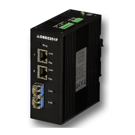
- Page 1 OPERATOR MANUAL OSD2251EP SERIES Lite Managed 4-Port Ethernet Switch with SNMP & VLAN 2 x 10/100/1000Base-T with PoE++ & 2 x Gigabit SFP...
- Page 3 OPTICAL SYSTEMS DESIGN INDEX 1 TECHNICAL SUMMARY ......................5 BRIEF DESCRIPTION ......................5 1.1.1 OVERVIEW ............................. 5 1.1.2 FEATURES AND BENEFITS ......................... 5 TYPICAL SYSTEM DESIGN ....................6 TECHNICAL SPECIFICATIONS .................... 7 PORT ALLOCATION ......................8 INSTALLATION AND OPERATION ..................9 INTRODUCTION........................
- Page 4 OPTICAL SYSTEMS DESIGN FIGURE 15: REDUNDANT RING CONNECTION ................20 FIGURE 16: BUS CONNECTION ......................20 FIGURE 17: SERIAL PORT SETTINGS ....................21 FIGURE 18: VERSION CHECK ......................23 FIGURE 19: FACTORY DEFAULT SETTING ..................24 FIGURE 20: IP CONFIGURATION ...................... 25 FIGURE 21: TOPOLOGY CHECK .......................
-
Page 5: Technical Summary
OPTICAL SYSTEMS DESIGN 1 TECHNICAL SUMMARY BRIEF DESCRIPTION 1.1.1 OVERVIEW The OSD2251EP is a 4-port lite managed switch with two Gigabit RJ45 and two Gigabit SFP uplink ports which can be used as standard ports or as a redundant fiber ring using OSD’s proprietary ring protocol. Each RJ45 can provide up to 60W PoE to power a wide range of devices. -
Page 6: Typical System Design
OPTICAL SYSTEMS DESIGN TYPICAL SYSTEM DESIGN Figure 1 below indicates a possible set-up for an OSD2251EP system. FIGURE 1: TYPICAL RING CONFIGURATION DOC ID: 10119201 PAGE 6 OSD2251EP OPERATOR MANUAL... -
Page 7: Technical Specifications
OPTICAL SYSTEMS DESIGN TECHNICAL SPECIFICATIONS TABLE 1: TECHNICAL SPECIFICATIONS Hardware Ethernet 2 x 10/100/1000Base-T RJ45, IEEE802.3i/802.3u/802.3ab Data Rate 10, 100, 1000Mbps, auto negotiate, auto MDIX Jumbo Frame Support 10KB 2 x Gigabit SFP ports (100Mbps or 1000Mbps user selectable) Optical Data Interface IEEE802.3z 1000Base-Lx/Sx, IEEE802.3u 100Base-Fx... -
Page 8: Port Allocation
OPTICAL SYSTEMS DESIGN PORT ALLOCATION Front Panel: There are two fixed copper ports for 10/100/1000Base-T and two SFP ports. Top Panel: The top panel consists of a 4-way 5.08mm terminal block power connector and a 4-way 3.5mm terminal block alarm connector. -
Page 9: Installation
OPTICAL SYSTEMS DESIGN 2 INSTALLATION AND OPERATION INTRODUCTION This section outlines the methods required to install and operate the OSD2251EP successfully. It should be studied carefully if damage to the equipment or poor results are to be avoided. This equipment has been fully tested prior to dispatch and is ready for immediate operation. However it is advisable to check for external transportation damage before operation. -
Page 10: Drawings And Dimensions
OPTICAL SYSTEMS DESIGN 2.2.2 DRAWINGS AND DIMENSIONS The OSD2251EP is designed to be wall mounted onto a DIN-Rail (35mm top hat) fixture or by using 4 x M4 captivated screws (DIN Rail mount requires removal and flanges repositioned – see below). The unit dimensions (excluding connectors, SFPs, etc) is shown in Figure 3 below. -
Page 11: Power Supply Connections
OPTICAL SYSTEMS DESIGN 2.2.3 LOCATION As with any electrical device, the OSD2251EP should be placed where the switch will not be subjected to extreme temperatures, humidity, or electromagnetic interference. Specifically, the site selected should meet the following requirements: The ambient temperature should be between -40°C to 75°C. -
Page 12: Alarm Connection
OPTICAL SYSTEMS DESIGN 2.2.5 ALARM CONNECTION The OSD2251EP has two monitoring alarm outputs: 1) Ring to Bus Alarm and 2) Temperature Alarm. The alarm connections and conditions for alarm outputs are as set out in Table 3. There are four pins on the 3.5mm terminal block used alarm output. -
Page 13: Usb Connector
OPTICAL SYSTEMS DESIGN 2.2.6 USB CONNECTOR The OSD2251EP has a USB – Type B connector located on the bottom of the unit that is used for Command Line Interface (CLI) from the PC to the OSD2251EP via the PC’s USB connector. See section 2.4 for further CLI information. -
Page 14: Mini Usb Port
OPTICAL SYSTEMS DESIGN 2.2.7 MINI USB PORT The Mini USB Port is used for uploading firmware updates. All OSD2251EP units will be shipped with the latest firmware already installed. This port has no function for end user. Mini USB Port... -
Page 15: Led Indicators
OPTICAL SYSTEMS DESIGN 2.2.8 LED INDICATORS FIGURE 10: PORT/LED TABLE 4: LED FUNCTION Function LED Colour Function Blink Green Gr/Am Amber Power No Power Unmanaged Ring/Bus... - Page 16 OPTICAL SYSTEMS DESIGN 2.2.9 CONTROLS The OSD2251EP has an 8-way DIP switch to control a number of functions. Table 5 outlines the function of each switch. 8-Way DIP Switch FIGURE 11: CONTROLS FIGURE 12: 8-WAY DIP SWITCH TABLE 5: 8-WAY DIP SWITCH SETTINGS...
- Page 17 OPTICAL SYSTEMS DESIGN TABLE 6: POE MODE SWITCH SETTINGS PoE Function 802.3at/af Standard Mode (Default Setting) Detection & Classification on one channel. Power supply on one channel Detection & Classification on one channel. Power supply on one channel, Legacy device feature enabled Reserved Mode Detection &...
-
Page 18: Fitting Sfp Connectors
OPTICAL SYSTEMS DESIGN 2.2.10 FITTING SFP CONNECTORS Care should be taken when inserting/removing the SFP connectors from SFP port 3 and 4 as SFP modules are Electrostatic (ES) sensitive and Electrostatic Discharge (ESD) precautions should be taken when installing. Ensure that the SFP is fully engaged and latched into position. -
Page 19: Operation
OPTICAL SYSTEMS DESIGN OPERATION When using the OSD2251EP for the first time, check that the unit is in good condition with no visible damage. Upon power up check that the indicators illuminate accordingly on power up (see Table 4). 2.3.1 CONNECTIONS For RJ45 connection use Category 5 (CAT5) or higher. - Page 20 OPTICAL SYSTEMS DESIGN To connect the OSD2251EP in a redundant ring configuration ports 3 and 4 must be used together with fiber SFPs. The non-ring ports (ports 1 & 2) should be used to connect to your Ethernet devices (eg.
-
Page 21: Command Line Interface
OPTICAL SYSTEMS DESIGN COMMAND LINE INTERFACE The Command Line Interface (CLI) is a useful tool for checking link status and debugging link connections. To enable the use of CLI the OSD2251EP must be connected to a PC with a serial port and an appropriate cable as specified in section 2.2.6. -
Page 22: Command Line Functions
OPTICAL SYSTEMS DESIGN 2.4.2 COMMAND LINE FUNCTIONS There are a number of command line functions that enables the user to obtain running information of a single OSD2251EP unit or the complete topology of the ring/bus network. This section explains the command lines and its functions. -
Page 23: Version Check
OPTICAL SYSTEMS DESIGN VERSION CHECK - <vc> FIGURE 18: VERSION CHECK Displays useful information regarding the unit: Software Version Number Software ID Number installed on the OSD2251EP Build Time Product Name DOC ID: 10119201 PAGE 23 OSD2251EP OPERATOR MANUAL... -
Page 24: Factory Default
OPTICAL SYSTEMS DESIGN FACTORY DEFAULT - <fd> FIGURE 19: FACTORY DEFAULT SETTING Resets the OSD2251EP to its default factory setting. A prompt question will appear “Do you want to Reset Configuration [y/n]? n – Exits the default configuration setting and returns to the home prompt. - Page 25 OPTICAL SYSTEMS DESIGN IP CONFIGURATION - <ipconfig> FIGURE 20: IP CONFIGURATION Displays the current IP address, Net mask and Gateway settings. To make changes to the IP address, Net mask and Gateway, at the prompt enter the new details in the following format;...
- Page 26 OPTICAL SYSTEMS DESIGN TOPOLOGY CHECK - <tc> FIGURE 21: TOPOLOGY CHECK In this case, only one OSD2251EP is connected to the USB cable. The display indicates the following; No: 1 – Number of units connected on the ring/bus (in this case only one unit) MAC_ADDRESS: 00:26:dc:00:1e:28 –...
- Page 27 OPTICAL SYSTEMS DESIGN In the example below there are four OSD2251EP connected in a ring configuration. FIGURE 22: TOPOLOGY CHECK No: 4 – Four units connected MAC_ADDRESS:– Displaying all the MAC addresses of the units connected on the ring/bus TOPOLOGY: Ring – Displaying type of connection.
- Page 28 OPTICAL SYSTEMS DESIGN NODE CHECK - <nc> FIGURE 23: NODE CHECK Node check obtains the running status of the node for the specific MAC address requested within the Ring/Bus. Correct entry format is as follows (MAC address specified below is an example);...
- Page 29 OPTICAL SYSTEMS DESIGN LOCAL NODE CHECK - <lnc> FIGURE 24: LOCAL NODE CHECK This command line displays the running status of the local node that the USB cable is plugged into. The information provided is the MAC address, Topology, Node Role, Port Role and Float Backup status.
- Page 30 OPTICAL SYSTEMS DESIGN FLOAT BACKUP ENABLE <fbe> FIGURE 25: FLOAT BACKUP ENABLED 1 No: 4 – Lists number of units connected (in this case 1,2,3,4) MAC_ADDRESS:– Displaying all the MAC addresses of the units connected on the ring/bus FLOAT_BACKUP: Enable – Displays all the units connected to the ring/bus having Float Backup enabled.
- Page 31 OPTICAL SYSTEMS DESIGN In Figure 26, node 1 will communicate with node 2, node 3 and node 4 via node 3. Node 2 will communicate to node 4 only via node 1 and 3. In the event of a fiber link being broken or disconnected (indicated by a cross) the backup branch will become the active branch.
- Page 32 OPTICAL SYSTEMS DESIGN FLOAT BACKUP DISABLE - <fbd> FIGURE 29: FLOAT BACKUP DISABLED 1 No: 4 – Lists number of units connected (in this case 1,2,3,4) MAC_ADDRESS:– Displaying all the MAC addresses of the units connected on the ring/bus FLOAT_BACKUP: Disable – Displays all the units connected to the ring/bus having Float Backup disabled.
- Page 33 OPTICAL SYSTEMS DESIGN In the event of a fiber link being broken or disconnected (indicated by a cross) the backup branch will become the active branch. If the link between node 1 and 3 is broken (see Figure 30), node 1 will communicate with node 3 via node 2 and node 4.
- Page 34 OPTICAL SYSTEMS DESIGN NODE IP SET - <node_ip_set> FIGURE 32: NODE IP SET This command line enables the user to setup the IP of the node with the given MAC address. Correct entry format is as follows (MAC, IP, mask and gateway address specified below is an example);...
- Page 35 OPTICAL SYSTEMS DESIGN REBOOT - <reboot/rb> FIGURE 34: REBOOT This command line enables the user to reboot the device either locally or remotely. Note: Rebooting should ONLY be used when network failure occurs. Rebooting a properly running network is not advised as network operation may cease.
-
Page 36: Snmp Configuration
OPTICAL SYSTEMS DESIGN SNMP CONFIGURATION - <config_snmp> FIGURE 35: SNMP This command line changes the root path. Typing ? will list the command lines within the SNMP directory. To return to the root directory, type in return and hit enter on the keyboard. - Page 37 OPTICAL SYSTEMS DESIGN FIGURE 36: SNMP MENU Set Trap Server <ts> This command sets the Trap Server IP address. The format is as follows; ts <IP address> Example: ts 192.168.0.100 Change Read Community <src> This command changes the SNMP read community. The format is as follows;...
-
Page 38: Port Control
OPTICAL SYSTEMS DESIGN PORT CONTROL - <portctrl> FIGURE 37: PORT CONTROL This command line allows the user to enable or disable all 4 ports. The format to enable all ports is as follows; portctrl <all> <on> The format to disable all ports is as follows;... - Page 39 OPTICAL SYSTEMS DESIGN 3 WEB GUI The OSD2251EP provides a web-based browser interface for configuring and monitoring the unit. This interface allows you to access the switch using any preferred web browser. This chapter describes how to configure the switch using its web-based browser interface.
-
Page 40: Logging On To The Switch
OPTICAL SYSTEMS DESIGN 3.1.1 LOGGING ON TO THE SWITCH IP A WITCH DDRESS In your web browser, specify the IP address of the switch. Default IP address is 192.168.0.99 To access the OSD2251EP a username and password will need to be entered. Factory default username is “admin”... - Page 41 OPTICAL SYSTEMS DESIGN 3.1.2 GUI MENU The user has access to Configure, Monitor or Maintain the OSD2251EP. Each section will be explained within this manual. DOC ID: 10119201 PAGE 41 OSD2251EP OPERATOR MANUAL...
-
Page 42: Configuration System
OPTICAL SYSTEMS DESIGN S ONFIGURATION YSTEM IP Configuration IP A DDRESS Configured: The IP address can be changed by modifying this window. Current: Displays the current saved IP address UBNET Configured: The Subnet Mask can be changed by modifying this window. -
Page 43: Configuration Snmp
OPTICAL SYSTEMS DESIGN SNMP V1/V2 ONFIGURATION NABLE : SNMP V1 is enabled : SNMP V1 is disabled NABLE : SNMP V2 is enabled : SNMP V2 is disabled SNMP R OMMUNITY Configured: The SNMP Read Community can be changed by modifying this window. - Page 44 OPTICAL SYSTEMS DESIGN SNMP V3 ONFIGURATION NABLE : SNMP V3 is enabled : SNMP V3 is disabled NGINE An octet string identifying the engine ID that this entry should belong to. The string must contain an even number (in hexadecimal format) with number of digits between 10 and 64, but all-zeros and all-'F's are not allowed.
- Page 45 OPTICAL SYSTEMS DESIGN RIVACY ROTOCOL Indicates the privacy protocol that this entry should belong to. Possible privacy protocols are: AES: An optional flag to indicate that this user uses AES authentication protocol. RIVACY ASSWORD A string identifying the privacy password phrase. The allowed string length is 8 to 32.
-
Page 46: Enable Vlan
OPTICAL SYSTEMS DESIGN VLAN ONFIGURATION VLAN Configuration VLAN NABLE : VLAN is enabled : VLAN is disabled VLAN Mode Configuration VLAN M A drop down menu will allow the user to select a VLAN mode: 802.1Q VLAN: Virtual Local Area Networks (VLANs) separate an existing physical network into multiple logical networks. - Page 47 OPTICAL SYSTEMS DESIGN Member of exactly one VLAN, the Port VLAN (a.k.a. Access VLAN), which by default is 1 Accepts untagged frames Discards all frames not classified to the Access VLAN On egress all frames are transmitted untagged ...
-
Page 48: Port Setting
OPTICAL SYSTEMS DESIGN P ONFIGURATION ETTING Indicates port number per row. Allows the user to manually set the port speed and duplex mode for the desired port. Auto: Auto Detect 10Mbps HDX: Half Duplex 10Mbps FDX: Full Duplex ... -
Page 49: Log Level
OPTICAL SYSTEMS DESIGN L ONFIGURATION Setup log activity Indicates port number per row. ODULE System Type EVEL Allows the user to manually set the Log Level to be monitored Disable: Disables the log monitoring for selected port ... -
Page 50: Igmp Snooping
OPTICAL SYSTEMS DESIGN IGMP ONFIGURATION IGMP Snooping Configuration IGMP S NOOPING A drop down menu allows user settings for the following; Enable: Enables IGMP Snooping Disable: Disables IGMP Snooping NREGISTERED ULTICAST LOODING A drop down menu allows user settings for the following;... -
Page 51: Igmp Version
OPTICAL SYSTEMS DESIGN IGMP VLAN ONFIGURATION Displays up to 10 entries from the IGMP Snooping VLAN table. The maximum number of entries is 10. ELETE Deletes selected VLAN IDs during the next save function. VLAN ID Displays VLAN IDs. - Page 52 OPTICAL SYSTEMS DESIGN P ONFIGURATION Allows the user to enable/disable individual PoE Ports. Displays port number per row NABLED : PoE enabled for selected port : PoE disabled for selected port DOC ID: 10119201 PAGE 52 OSD2251EP OPERATOR MANUAL...
-
Page 53: System Info
OPTICAL SYSTEMS DESIGN S ONITOR YSTEM This menu is identical to the start-up menu. A table displaying useful system information is also displayed containing MAC address, Serial Number, Software, IP address, etc. DOC ID: 10119201 PAGE 53 OSD2251EP OPERATOR MANUAL... -
Page 54: Monitor Port
OPTICAL SYSTEMS DESIGN P ONITOR Monitors each port activity. /SFP OPPER Indicates the port connection: Either Copper or SFP Indicates the role of each ports connections: Switch Port, Ring Port, Bus Port. Up: Connection established Down: No Connection detected PEED Indicates the port connection speed in Mbps. -
Page 55: Mac Address
OPTICAL SYSTEMS DESIGN T ONITOR OPOLOGY Shows the topology map of available devices in the connected ring/bus. Unit number within the connected ring/bus MAC A DDRESS Displays the MAC address number for each unit connected on the ring/bus OPOLOGY Indicates the topology type;... - Page 56 OPTICAL SYSTEMS DESIGN P ONITOR Indicates port number per row. HANNEL Indicates the channel number of the port AlternativeA: Pins 1,2 and Pins 3,6 on RJ45 AlternativeB: Pins 4,5 and Pins 7,8 on RJ45 URRENT Indicates the current drawn from the relevant PoE port/channel...
- Page 57 OPTICAL SYSTEMS DESIGN S ONITOR YSTEM Monitors and logs activity Event number Records a time-stamp of the log activity A brief description of the type of event DOC ID: 10119201 PAGE 57 OSD2251EP OPERATOR MANUAL...
- Page 58 OPTICAL SYSTEMS DESIGN IGMP ONITOR IGMP Snooping Status VLAN Indicates the VLAN address of device being monitored UERIES ERSION Working Querier version of IGMP operating on current hosts. ERSION Working version of IGMP operating on current hosts. UERIES ECEIVED...
-
Page 59: Maintenance
OPTICAL SYSTEMS DESIGN U AINTENANCE PLOAD Use this section to upload OSD released update software. Click the button and navigate to the folder where the software is saved then select the file. Click the button to start the upload process. - Page 60 OPTICAL SYSTEMS DESIGN S AINTENANCE ECURITY Use this section to change user name and passwords URRENT SERNAME Displays the current or default user name for the unit. Default username is “admin” URRENT ASSWORD Enter the current password in order to change username or password. Default password is left blank for user to select when setting up the unit.
-
Page 61: System Reboot
OPTICAL SYSTEMS DESIGN F AINTENANCE ACTORY EFAULT Clicking this button will reset the unit to factory default settings including the user name and current password. S AINTENANCE YSTEM EBOOT Use the section to reboot the system when any switch settings are changes for the new settings to take effect. -
Page 62: External Inspection
OPTICAL SYSTEMS DESIGN 4 MAINTENANCE INTRODUCTION The following section outlines the fault-finding procedure for the OSD2251EP modems. Please take note of the following: ▲ Personnel without appropriate training should not attempt any maintenance except that outlined below. ▲ If further maintenance is attempted you are warned that every care should be taken to ensure that... -
Page 63: Warranty Period
For warranty period, please contact your local OSD distributor. REPAIRS Optical Systems Design reserves the right to repair or replace faulty modules/units. Please obtain a “Return Material Authorisation” (RMA) form and number before returning goods. Goods must be returned in adequate packing material to Optical Systems Design, Warriewood or its nominated authorised representative, for all repairs. - Page 64 OPTIC L Optical Systems Design Pty. Ltd. 7/1 Vuko Pl. Warriewood 2102 SYSTEMS P.O. Box 891 Mona Vale N.S.W. Australia 2103 Telephone: +61 2 9913 8540 Facsimile: +61 2 9913 8735 DESIGN Email: sales@osd.com.au Web Site: www.osd.com.au PTY LTD A.B.N. 83 003 020 504...
Need help?
Do you have a question about the OSD2251EP Series and is the answer not in the manual?
Questions and answers