Table of Contents
Advertisement
Quick Links
Advertisement
Table of Contents

Related Manuals for Optical Systems Design OSD2244V Series


Summary of Contents for Optical Systems Design OSD2244V Series
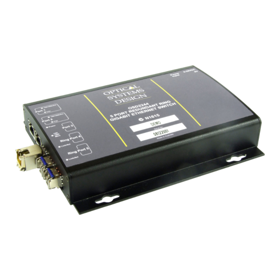
- Page 1 OPERATOR MANUAL OSD2244V SERIES 5-PORT REDUNDANT RING GIGABIT ETHERNET SWITCH...
- Page 3 OPTICAL SYSTEMS DESIGN INDEX 1 TECHNICAL SUMMARY ......................5 BRIEF DESCRIPTION ......................5 1.1.1 OVERVIEW ............................ 5 1.1.2 APPLICATIONS ..........................5 1.1.3 FEATURES AND BENEFITS ......................5 TYPICAL CONFIGURATION ....................6 TECHNICAL SPECIFICATIONS ................... 7 OSD2244V FRONT AND REAR PANELS ................8 INSTALLATION AND OPERATION ..................
- Page 4 OPTICAL SYSTEMS DESIGN WARRANTY PERIOD ......................56 REPAIRS ..........................56 5.2.1 WARRANTY REPAIRS ....................... 56 5.2.2 OUT-OF-WARRANTY REPAIRS ....................56 5.2.3 SITE REPAIRS ..........................56 5.2.4 EXCLUSIONS ..........................56 FIGURE 1: OSD2244V TYPICAL RING CONFIGURATION .............. 6 FIGURE 2: OSD2244V CONNECTORS ....................8 FIGURE 3: OSD2244V MOUNTING DIMENSIONS ................
- Page 5 OPTICAL SYSTEMS DESIGN 1 TECHNICAL SUMMARY BRIEF DESCRIPTION 1.1.1 OVERVIEW The OSD2244V is a 5-port Ethernet switch with simple network management designed to operate in tough industrial applications providing real-time redundant performance. It has two 10/100/1000Base- T RJ45 copper ports, two SFP ports for the ring and one SFP port which can be specified by the user for 1000Base-Lx fiber mode or as 1000Base-T RJ45 copper.
-
Page 6: Typical Configuration
OPTICAL SYSTEMS DESIGN TYPICAL CONFIGURATION Figure 1 below indicates a possible set-up for an OSD2244V system. FIGURE 1: OSD2244V TYPICAL RING CONFIGURATION DOC ID: 10111103 PAGE 6 OSD2244V OPERATOR MANUAL... -
Page 7: Technical Specifications
OPTICAL SYSTEMS DESIGN TECHNICAL SPECIFICATIONS TABLE 1: TECHNICAL SPECIFICATIONS SPECIFICATION PERFORMANCE IEEE802.3ab IEEE802.3u, IEEE802.3i, Base-T Ethernet at 10, 100 or 1000Mbps Electrical Data Interface Electrical Data Connector RJ45 on the two fixed copper ports 1 and 2 and for SFP modules USB 2.0... - Page 8 OPTICAL SYSTEMS DESIGN OSD2244V FRONT AND REAR PANELS There are two fixed copper ports for 10/100/1000Base-T and three optional SFP ports which can be either copper or fiber on the front panel. The rear panel consists of a 6-way terminal block power connector, 4-Way DIP switch, Type-A USB connector and a Type-B USB connector.
-
Page 9: Installation
OPTICAL SYSTEMS DESIGN 2 INSTALLATION AND OPERATION INTRODUCTION This section outlines the methods required to install and operate the OSD2244V successfully. It should be studied carefully if damage to the equipment or poor results are to be avoided. This equipment has been fully tested prior to dispatch and is ready for immediate operation. However it is advisable to check for external transportation damage before operation. - Page 10 OPTICAL SYSTEMS DESIGN 2.2.2 OSD2244V DRAWINGS AND DIMENSIONS The OSD2244V standalone module is designed to be mounted on an even surface and to be secured by means of M4 or smaller screws. The OSD2244V card version is designed to be inserted into a chassis and secured by means of captivated screws.
-
Page 11: Power Supply Connections
OPTICAL SYSTEMS DESIGN 2.2.3 POWER SUPPLY CONNECTIONS The OSD2244V card version is powered from the OSD370 or OSD350 chassis. DC power on the OSD2244V card version is connected via the DB9 connector. The card version of the OSD2244V should be fixed into the OSD370 (or OSD350) chassis using the captivated screws. The card can be plugged in or out of the OSD370 (or OSD350) chassis with power on or off. -
Page 12: Usb Connector
OPTICAL SYSTEMS DESIGN 2.2.5 USB CONNECTOR The OSD2244V has a USB – Type B connector located on the rear of the unit that is used for Command Line Interface (CLI) from the PC to the OSD2244V via the PC’s USB connector. See section 2.5 for further CLI information. -
Page 13: Port Allocation And Led Indicators
OPTICAL SYSTEMS DESIGN 2.2.6 PORT ALLOCATION AND LED INDICATORS Port 5 Port 4 Port 3 Port 2 Port 1 Case 1 1 1 1 2 2 2 2 FIGURE 8: PORT/LED 3 3 3 3 4 4 4 4 5 5 5 5... - Page 14 OPTICAL SYSTEMS DESIGN 2.2.7 CONTROLS The OSD2244V has a 4-way DIP switch to control a number of functions. Table 4 outlines the function of each switch. 4-Way DIP Switch FIGURE 9: OSD2244V CONTROLS Fiber Speed Select Firmware Update Enable ON Position...
-
Page 15: Fitting Sfp Connectors
OPTICAL SYSTEMS DESIGN 2.2.8 FITTING SFP CONNECTORS Care should be taken when inserting/removing the SFP connectors from SFP port 3,4 and 5 as SFP modules are Electrostatic (ES) sensitive and Electrostatic Discharge (ESD) precautions should be taken when installing. Ensure that the SFP is fully engaged and latched into position. - Page 16 OPTICAL SYSTEMS DESIGN OSD2244V OPERATION When using the OSD2244V for the first time, check that the unit is in good condition with no visible damage. If a card version is used, insert it in an appropriate slot on the OSD370 or OSD350 chassis and check that the indicators illuminate accordingly on power up (see Table 3).
- Page 17 OPTICAL SYSTEMS DESIGN To connect the OSD2244V in a redundant ring configuration ports 4 and 5 must be used together with fiber SFPs. The non-ring ports (ports 1,2, &3) should be used to connect to your Ethernet devices (eg. Cameras, PLCs, computers, etc.) Figure 13 shows the connection method.
-
Page 18: Firmware Updates
OPTICAL SYSTEMS DESIGN FIRMWARE UPDATES All OSD2244V units will be shipped with the latest firmware already installed. The Type- A USB port is used for any firmware updates. To enable the OSD2244V for firmware updates, switch 4 will need to be toggled to the ‘on’... - Page 19 OPTICAL SYSTEMS DESIGN Disable Create desktop shortcut and Show readme and click Finish. • DOC ID: 10111103 PAGE 19 OSD2244V OPERATOR MANUAL...
-
Page 20: Installing Usb Driver
OPTICAL SYSTEMS DESIGN 2.4.2 INSTALLING USB DRIVER Toggle switch 4 to ‘on’ position (see Figure 10) before unit is powered on. • • Connect USB cable between target unit and PC with FLIP installed. Power the OSD2244V unit and follow steps outlined below;... - Page 21 OPTICAL SYSTEMS DESIGN DOC ID: 10111103 PAGE 21 OSD2244V OPERATOR MANUAL...
-
Page 22: Upgrade Firmware
OPTICAL SYSTEMS DESIGN DRIVER FOR WINDOWS 7 64bit For 64bit operating systems use directory named win7 driver on CD as destination location for driver file. 2.4.3 UPGRADE FIRMWARE Copy firmware directory from CD to c:\osd as shown below DOC ID: 10111103... -
Page 23: Installation Check
OPTICAL SYSTEMS DESIGN Upgrade Firmware Click the OSD2244RevXX Firmware.bat file supplied on the CD. Note: XX denotes revision number of firmware. The batch file contains a small command to install the firmware. The main command is as follows; batchisp -device at32uc3a1512 -hardware usb -operation erase f memory flash blankcheck loadbuffer c:\osd\firmware\60001701.hex program verify start reset 0... -
Page 24: Command Line Interface
OPTICAL SYSTEMS DESIGN COMMAND LINE INTERFACE The Command Line Interface (CLI) is a useful tool for checking link status and debugging link connections. To enable the use of CLI the OSD2244V must be connected to a PC with a serial port and an appropriate cable as specified in section 2.2.5. -
Page 25: Command Line Functions
OPTICAL SYSTEMS DESIGN 2.5.2 COMMAND LINE FUNCTIONS There are a number of command line functions that enables the user to obtain running information of a single OSD2244V unit or the complete topology of the ring/bus network. This section explains the command lines and its functions. - Page 26 OPTICAL SYSTEMS DESIGN TOPOLOGY CHECK - <tc> Command Line FIGURE 18: TOPOLOGY CHECK In this case, only one OSD2244V is connected to the USB cable. The display indicates the following; No: 1 – Number of units connected on the ring/bus (in this case only one unit) MAC_ADDRESS: 00:26:dc:00:00:6d –...
- Page 27 OPTICAL SYSTEMS DESIGN In the example below there are four OSD2244V connected in a ring configuration. FIGURE 19: TOPOLOGY CHECK No: 4 – Four units connected MAC_ADDRESS:– Displaying all the MAC addresses of the units connected on the ring/bus TOPOLOGY: Ring – Displaying type of connection.
- Page 28 OPTICAL SYSTEMS DESIGN NODE CHECK - <nc> Command Line FIGURE 20: NODE CHECK The Node Check command line is a useful command for checking the running status of any remote node connected to the ring/bus topology from any particular node that the USB cable is plugged into.
- Page 29 OPTICAL SYSTEMS DESIGN LOCAL NODE CHECK - <lnc> Command Line FIGURE 21: LOCAL NODE CHECK This command line displays the running status of the local node that the USB cable is plugged into. The information provided is the MAC address, Topology, Node Role, Port Role and Float Backup status.
- Page 30 OPTICAL SYSTEMS DESIGN FLOAT BACKUP ENABLE <fbe> Command Line FIGURE 22: FLOAT BACKUP ENABLED 1 No: 4 – Lists number of units connected (in this case 1,2,3,4) MAC_ADDRESS:– Displaying all the MAC addresses of the units connected on the ring/bus FLOAT_BACKUP: Enable –...
- Page 31 OPTICAL SYSTEMS DESIGN In Figure 23, node 1 will communicate with node 2, node 3 and node 4 via node 3. Node 2 will communicate to node 4 only via node 1 and 3. In the event of a fiber link being broken or disconnected (indicated by a cross) the backup branch will become the active branch.
- Page 32 OPTICAL SYSTEMS DESIGN FLOAT BACKUP DISABLE - <fbd> Command Line FIGURE 26: FLOAT BACKUP DISABLED 1 No: 4 – Lists number of units connected (in this case 1,2,3,4) MAC_ADDRESS:– Displaying all the MAC addresses of the units connected on the ring/bus FLOAT_BACKUP: Disable –...
- Page 33 OPTICAL SYSTEMS DESIGN In the event of a fiber link being broken or disconnected (indicated by a cross) the backup branch will become the active branch. If the link between node 1 and 3 is broken (see Figure 27) , node 1 will communicate with node 3 via node 2 and node 4.
-
Page 34: Virtual Lan (Vlan)
OPTICAL SYSTEMS DESIGN 3 VIRTUAL LAN (VLAN) INTRODUCTION VLAN simply means Virtual Local Area Network or in other terms - Virtual LAN. A VLAN is a group of devices (OSD2244V) within a LAN which can communicate with each other as if they were on a common LAN. -
Page 35: Vlan Protocol
OPTICAL SYSTEMS DESIGN VLAN PROTOCOL The OSD2244V employs frame tagging to identify the VLAN the packet belongs to (see Figure 30). The VLAN frame tag is placed on the frame when the frame reaches a switch from an access port, which is a member of a VLAN. - Page 36 OPTICAL SYSTEMS DESIGN Ingress Manager: 1) Decide if the ingressing frame is allowed to enter into OSD2244V. 2) Add 802.1ac Tag to an Untagged Frame and decide whether or not to modify the VID and Priority Level of a Tagged Frame. VID is decided firstly and then Priority Level.
- Page 37 OPTICAL SYSTEMS DESIGN FIGURE 32: PRIORITY AND VID TAG SELECTION FLOW CHART 3.2.2 PRIORITY REMAPPING AND SCHEDULING MODE FOR QUEUE MANAGER Priority Remapping The OSD2244V Queue Manager supports 4-Level priority only. As a result, the 802.1p 7- Level priority structure requires to be remapped to a 4-Level priority structure. Table 6 outlines the details.
- Page 38 OPTICAL SYSTEMS DESIGN TABLE 6: PRIORITY REMAPPING & SCHEDULING FOR QUEUE MANAGER PRI of frame PRI of egressing Weighted Ratio for Remapped PRI used entering Queue frame Scheduling Mode = by Queue Manager Manager (egressing tagged) Weighted 3.2.3 CANONICAL FORMAT INDICATOR (CFI) The CFI bit of the IEE Tag is ignored and left unmodified by the OSD2244V 3.2.4...
-
Page 39: Vlan Table
OPTICAL SYSTEMS DESIGN 3.2.5 VLAN TABLE The VLAN Table (accessed via the CLI) displays the database of OSD2244V’s VLAN setup. It indicates all information relevant to the VID including membership, egress mode of every member port and priority level for this OSD2244V VID. Each of the entries in the VLAN table represents a VLAN group, which is identified by its VID. -
Page 40: Vlan Configurations
OPTICAL SYSTEMS DESIGN VLAN CONFIGURATIONS It is highly recommended to perform configurations on each OSD2244Vunit prior to connecting any devices and optical fiber. It is also equally important to understand the topology and network the user is attempting to achieve. A topology diagram is useful when setting the system up such as shown in Figure 34. -
Page 41: Configuration Storage
OPTICAL SYSTEMS DESIGN The following information regarding VLAN configurations and setups requires knowledge of the Command Line Interface (CLI) which is described in section 2.5. 3.3.1 CONFIGURATION STORAGE A non-volatile memory is used to store VLAN configurations for the OSD2244V, therefore all configurations will be restored back to set values at power on. - Page 42 OPTICAL SYSTEMS DESIGN VLAN TABLE SHOW - <vts> Command Line FIGURE 36: VLAN TABLE SHOW The VLAN Table displays the database of OSD2244V’s VLAN setup. It indicates all information relevant to the VID including membership, egress mode of every member port and priority level for this OSD2244V VID.
- Page 43 OPTICAL SYSTEMS DESIGN PORT CONFIGURATION SHOW - <vps> - Command Line FIGURE 37: PORT CONFIGURATION SHOW The Port Configuration Check is used for checking the settings of all non-ring ports. Every non-ring port has one row in the table. Figure 37 shows the default configuration as an example.
-
Page 44: Default Configuration
OPTICAL SYSTEMS DESIGN 3.3.3 DEFAULT CONFIGURATION The default configuration upon shipment of the OSD2244V VLAN Mode is: Normal (802.1Q VLAN is disabled). Note: to enable 802.1Q VLAN type vps on the CLI. See section 3.4 for detailed information. When enabling the 802.1Q VLAN the initial configurations are as shown Figure 38. Note: to view VID table type vts on the CLI. -
Page 45: Vlan Setup
OPTICAL SYSTEMS DESIGN COMMAND LINE INTERFACE (CLI) FOR VLAN 3.4.1 VLAN SETUP As mentioned is section 3.3 there are a few steps to note before setting up the OSD2244V VLAN functions; Each OSD2244V unit requires VLAN settings to be configured individually •... - Page 46 VLAN Mode Command Description Format Function Description Command Normal 802.1Q √ √ Enable or disable 802.1Q VLAN for OSD2244V. vlan_mode_set { vms} <mode_value> √ √ vlan_mode_check {vmc} Check current VLAN mode. √ vpdv Set Port Default VID for non-ring ports (port1, 2 and 3). vlan_port_defatult_vid {vpdv} <p1_vid, p2_vid, p3_vid>...
-
Page 47: Vlan Cli Commands
OPTICAL SYSTEMS DESIGN VLAN CLI COMMANDS VLAN MODE SET – Enable or disable 802.1Q VLAN Factory CLI Syntax Parameters Example Command Default 0: Normal (VLAN disabled vms <mode value> vms 1 1: 802.1Q VLAN Note: To reset the OSD2244V VLAN configurations to factory default set the parameter to 0 (vms 0) then enable VLAN 802.1Q (vms 1) - Page 48 OPTICAL SYSTEMS DESIGN VLAN ENTRY TABLE DELETE – Delete an entry from 802.1Q VLAN table. Factory CLI Syntax Parameters Example Command Default vetd vetd <vid> 0 – 254 vetd 101 VLAN ENTRY TABLE FLUSH – Delete all entries from 802.1Q VLAN table.
- Page 49 OPTICAL SYSTEMS DESIGN VLAN DISCARD TAGGED FRAME – Discard/Not Discard 802.3ac Tagged frames for non-ring ports. Factory CLI Syntax Parameters Example Command Default 0: Not Discard vdtf vdtf <p1 bit, p2 bit, p3 bit> vdtf 1, 0, 0 1: Discard VLAN DISCARD UNTAGGED FRAME –...
- Page 50 OPTICAL SYSTEMS DESIGN VLAN SETTING SCENARIOS The following scenarios are a few examples of the OSD2244V setup. A topology diagram is used as an example together with the VLAN CLI input commands used to set the system up for the given topology.
- Page 51 OPTICAL SYSTEMS DESIGN TABLE 8: SCENARIO 1 OSD2244V OSD2244V OSD2244V OSD2244V vms 1 vms 1 vms 1 vms 1 vpdv 10, 1, 1 vpdv 10, 1, 40 vpdv 1, 20, 1 vpdv 40, 1, 30 vpem 0, 0, 1 vpem 0, 0, 0...
- Page 52 OPTICAL SYSTEMS DESIGN DOC ID: 10111101 PAGE 52 OSD2244V OPERATOR MANUAL...
- Page 53 OPTICAL SYSTEMS DESIGN 3.6.2 SCENARIO 2 In this scenario, there are three IP Cameras connected to three OSD2244V (no2, 3 and 4) respectively. IP Camera No1 belongs to VLAN10, IP Camera No2 belongs to VLAN20 and IP Camera No3 belongs to VLAN30.
- Page 54 OPTICAL SYSTEMS DESIGN The configurations for this scenario: OSD2244V OSD2244V OSD2244V OSD2244V vms 1 vpdv 10, 20, 30 vpem 0, 0, 0 vvos 1, 1, 1 Same as No1 Same as No1 Same as No1 Commands veta 10, 0, 1, 0, 0...
-
Page 55: External Inspection
OPTICAL SYSTEMS DESIGN 4 MAINTENANCE INTRODUCTION The following section outlines the fault-finding procedure for the OSD2244V modems. Please take note of the following: Personnel without appropriate training should not attempt any maintenance except that outlined ▲ below. If further maintenance is attempted you are warned that every care should be taken to ensure that ▲... -
Page 56: Warranty Period
For warranty period, please contact your local OSD distributor. REPAIRS Optical Systems Design reserves the right to repair or replace faulty modules/units. Please obtain a “Return Material Authorisation” (RMA) form and number before returning goods. Goods must be returned in adequate packing material to Optical Systems Design, Warriewood or its nominated authorised representative, for all repairs. - Page 57 OPTIC L Optical Systems Design Pty. Ltd. 7/1 Vuko Pl. Warriewood 2102 SYSTEMS P.O. Box 891 Mona Vale N.S.W. Australia 2103 Telephone: +61 2 9913 8540 DESIGN Facsimile: +61 2 9913 8735 Email: sales@osd.com.au Web Site: www.osd.com.au PTY LTD A.B.N. 83 003 020 504...
Need help?
Do you have a question about the OSD2244V Series and is the answer not in the manual?
Questions and answers