
Subscribe to Our Youtube Channel
Related Manuals for Optical Systems Design OSD2524


Summary of Contents for Optical Systems Design OSD2524
-
Page 1: Index
Quick Start Guide OSD2524 MANAGED 20 x 10/100/1000BASE-T, 4 x COMBO AND 2 x 1G ETHERNET SWITCH... -
Page 3: Table Of Contents
OPTICAL SYSTEMS DESIGN INDEX 1 INTRODUCTION ........................4 INSTALLATION........................4 OSD2524 FRONT AND REAR PANELS................. 5 FRONT PANEL ........................5 REAR P ..........................5 ANEL POWER SUPPLY CONNECTIONS ..................6 LED INDICATORS ........................7 FITTING SFP CONNECTORS ....................8 COMBO PORTS ........................8 CLI OVERVIEW ........................ -
Page 4: Introduction
OPTICAL SYSTEMS DESIGN 1 INTRODUCTION Thank you for choosing the OSD2524 20-Port Gigabit Managed Ethernet Switch. This Quick Start Guide is designed to guide you through the installation and basic software function. 2 INSTALLATION ELECTROMAGNETIC COMPATIBILITY WARNING: This is a Class A product. In a domestic environment this product may cause radio interference in which case the user may be required to take adequate measures. -
Page 5: Osd2524 Front And Rear Panels
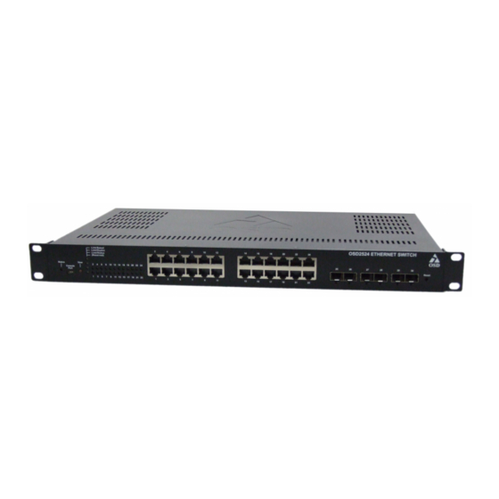
OPTICAL SYSTEMS DESIGN 3 OSD2524 FRONT AND REAR PANELS FRONT PANEL 1 2 3 4 FIGURE 1: FRONT PANEL Board Status LED USB Console Port View LED Mode Button View Mode LEDs Indicators Port Status LEDs RJ45 Copper Ports SFP Fiber Ports... -
Page 6: Power Supply Connections
Dual Redundant DC Power Version Connect the dual redundant power to the 4-way terminal block located on the rear of the unit. The OSD2524 DC version requires external +10 to +36V @ 40VA Max power. FIGURE 3: DC POWER CONNECTION... -
Page 7: Led Indicators
Blinking - Traffic • Status Mode: Green – Connection good • Off – No Connection • Fiber Port Status Green – 1Gbps • Off – No Connection • Blinking - Traffic • DOC ID: 10117701 PAGE 7 OSD2524 QUICK START GUIDE... -
Page 8: Fitting Sfp Connectors
Note that ports 21, 22, 23, and 24 are Combo Ports and either the RJ45 ports or SFP ports will operate at one time. Each port is label accordingly and the combo ports are marked by the white outline. FIGURE 6: COMBO PORT ALLOCATION DOC ID: 10117701 PAGE 8 OSD2524 QUICK START GUIDE... -
Page 9: Cli Overview
OPTICAL SYSTEMS DESIGN 8 CLI OVERVIEW CONNECT TO CLI The Silicon Laboratories CP210x VCP Drivers is needed to be installed on the PC before connecting the switch. DOC ID: 10117701 PAGE 9 OSD2524 QUICK START GUIDE... -
Page 10: Cli Command For Ip Configuration
IP address. copy running-config startup- config: Save the current configuration to start-up configuration. • PS: All configuration changes must be saved otherwise all the changes will be lost after rebooting! DOC ID: 10117701 PAGE 10 OSD2524 QUICK START GUIDE... -
Page 11: Gui Overview
If the multiple IP addresses are required, click Add Interface to add more IP interface. Click Save to save the configuration. Use new IP address to access the switch. PS: All configuration changes must be saved otherwise all the changes will be lost after rebooting! DOC ID: 10117701 PAGE 11 OSD2524 QUICK START GUIDE... -
Page 12: Users Authentication
In the tree map on the left, expand the Configuration Security Switch Users Click admin to change the current admin account setting. If multiple users are required, click Add New User DOC ID: 10117701 PAGE 12 OSD2524 QUICK START GUIDE... -
Page 13: Save Configuration To Start-Up
PS: All configuration changes must be saved otherwise all the changes will be lost after rebooting! SAVE CONFIGURATION TO START-UP In the treemap below, expand the Maintenance and expand Configuration, then select Save startup- config Click Save Configuration to save the configuration on start-up. DOC ID: 10117701 PAGE 13 OSD2524 QUICK START GUIDE... -
Page 14: Warranty
For warranty period, please call your local OSD distributor. 10.2 REPAIRS Optical Systems Design reserves the right to repair or replace faulty modules/units. Please obtain a “Return Material Authorisation” (RMA) form and number before returning goods. Goods must be returned in adequate packing material to Optical Systems Design, Warriewood or its nominated authorised representative, for all repairs. - Page 15 OPTICAL SYSTEMS DESIGN DOC ID: 10117701 PAGE 15 OSD2524 QUICK START GUIDE...
- Page 16 OPTIC L Optical Systems Design Pty. Ltd. 7/1 Vuko Pl. Warriewood 2102 SYSTEMS P.O. Box 891 Mona Vale N.S.W. Australia 2103 Telephone: +61 2 9913 8540 Facsimile: +61 2 9913 8735 DESIGN Email: sales@osd.com.au Web Site: www.osd.com.au PTY LTD A.B.N. 83 003 020 504...
Need help?
Do you have a question about the OSD2524 and is the answer not in the manual?
Questions and answers