
Related Manuals for Optical Systems Design OSD2790SFP


Summary of Contents for Optical Systems Design OSD2790SFP
-
Page 1: Index
Quick Start Guide OSD2790SFP MANAGED 24 x 100M/1G SFP + 4 x 1G TRUNK/UPLINK SFP ETHERNET SWITCH... -
Page 3: Table Of Contents
2.1.2 APPLICATIONS ........................4 2.1.3 FEATURES AND BENEFITS ..................... 5 TECHNICAL SPECIFICATIONS ................... 6 INSTALLATION........................7 OSD2790SFP FRONT AND REAR PANELS ................. 8 FRONT PANEL ........................8 REAR P ..........................8 ANEL POWER SUPPLY CONNECTIONS ..................9 LED INDICATORS ........................9 FITTING SFP CONNECTORS .................... -
Page 4: Introduction
2.1.1 OVERVIEW The OSD2790SFP is a managed 24 port 100M/1G SFP + 4 port 1G Trunk/Uplink SFP Ethernet Switch. A number of various SFPs can be used including 100Mbps, 1Gbps duplex, single-fiber and RJ45 Copper. Please see OSD SFP datasheets for options available. -
Page 5: Features And Benefits
RFC 4188 Bridge MIB • DHCP client • Private MIB framework • Port mirroring • IEEE 802.1 MSTP MIB • IEEE 802.1AB LLDP Security • Port-based 802.1X • Web and CLI authentication and authorization DOC ID: 10117502 PAGE 5 OSD2790SFP QUICK START GUIDE... -
Page 6: Technical Specifications
One IEC power inlet module for the standard AC powered version Two IEC power inlet modules for the optional redundant AC powered version 443W x 300D x 44H Dimensions of Enclosure (mm) 1022790SFP01 DOC ID: 10117502 PAGE 6 OSD2790SFP QUICK START GUIDE... -
Page 7: Installation
OPTICAL OUTPUT OPERATION WARNING: Laser Safety: Class 1 Laser Product (SFP) per IEC 60825-1:2014 standard. Class 1 The OSD2790SFP is a Class 1 laser product when SFPs are fitted PRECAUTIONS ▲... -
Page 8: Osd2790Sfp Front And Rear Panels
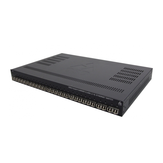
OPTICAL SYSTEMS DESIGN 4 OSD2790SFP FRONT AND REAR PANELS FRONT PANEL FIGURE 1: FRONT PANEL PSU1 Status LED PSU2 Status LED Status LED USB Console Port 24 x 100/1000M SFP ports with 100M/1G Link/Activity/Speed LEDs 4 x 1G Trunk/Uplink SFP ports with 100M/1G Link/Activity/Speed LEDs... -
Page 9: Power Supply Connections
OPTICAL SYSTEMS DESIGN 5 Power Supply Connections Connect the two IEC Power connectors to PSU 1 and PSU 2 located on the rear of the unit. The OSD2790SFP requires external 90 to 264V @ 55VA Max power. FIGURE 3: POWER CONNECTION... -
Page 10: Fitting Sfp Connectors
Removing SFP – Remove fiber connector. Pull the SFP lever down to unlock SFP from housing. Using the lever, gently pull the SFP out. Fiber SFP Inserting Removing FIGURE 4: FITTING/REMOVING SFP CONNECTORS DOC ID: 10117502 PAGE 10 OSD2790SFP QUICK START GUIDE... -
Page 11: Cli Overview
OPTICAL SYSTEMS DESIGN 8 CLI OVERVIEW CONNECT TO CLI The Silicon Laboratories CP210x VCP Drivers is required to be installed on the PC before connecting the switch. DOC ID: 10117502 PAGE 11 OSD2790SFP QUICK START GUIDE... -
Page 12: Cli Command For Ip Configuration
IP address. • copy running-config startup- config: Save the current configuration to start-up configuration. PS: All configuration changes must be saved otherwise all the changes will be lost after rebooting! DOC ID: 10117502 PAGE 12 OSD2790SFP QUICK START GUIDE... -
Page 13: Gui Overview
Clicking the Logout button will logout the current user. OGOUT Clicking the Help button will open a help window for the current open menu window and display all functions and input arguments for that page. DOC ID: 10117502 PAGE 13 OSD2790SFP QUICK START GUIDE... -
Page 14: Ip Configuration
If the multiple IP addresses are required, click Add Interface to add more IP interface. Click Save to save the configuration. Use new IP address to access the switch. PS: All configuration changes must be saved otherwise all the changes will be lost after rebooting! DOC ID: 10117502 PAGE 14 OSD2790SFP QUICK START GUIDE... -
Page 15: Users Authentication
Click admin to change the current admin account setting. If multiple users are required, click Add New User PS: All configuration changes must be saved otherwise all the changes will be lost after rebooting! DOC ID: 10117502 PAGE 15 OSD2790SFP QUICK START GUIDE... -
Page 16: Save Configuration To Start-Up
Click Save Configuration to save the configuration on start-up. PORT SPEED SETTING The default port speed settings for the OSD2790SFP is 1Gbps. If the user uses 100Mbps SFP devices, the unit will have to have those ports manually set to 100Mbps for correct operation. In the tree map below expand the Configuration menu and select Ports. -
Page 17: Warranty
For warranty period, please call your local OSD distributor. 10.2 REPAIRS Optical Systems Design reserves the right to repair or replace faulty modules/units. Please obtain a “Return Material Authorisation” (RMA) form and number before returning goods. Goods must be returned in adequate packing material to Optical Systems Design, Warriewood or its nominated authorised representative, for all repairs. - Page 18 OPTICAL SYSTEMS DESIGN DOC ID: 10117502 PAGE 18 OSD2790SFP QUICK START GUIDE...
- Page 19 OPTICAL SYSTEMS DESIGN DOC ID: 10117502 PAGE 19 OSD2790SFP QUICK START GUIDE...
- Page 20 OPTIC L Optical Systems Design Pty. Ltd. 7/1 Vuko Pl. Warriewood 2102 SYSTEMS P.O. Box 891 Mona Vale N.S.W. Australia 2103 Telephone: +61 2 9913 8540 Facsimile: +61 2 9913 8735 DESIGN Email: sales@osd.com.au Web Site: www.osd.com.au PTY LTD A.B.N. 83 003 020 504...
Need help?
Do you have a question about the OSD2790SFP and is the answer not in the manual?
Questions and answers