
Related Manuals for Optical Systems Design OSD2251BP Series


Summary of Contents for Optical Systems Design OSD2251BP Series
- Page 1 OPERATOR MANUAL OSD2251BP SERIES 4-PORT REDUNDANT RING GIGABIT ETHERNET SWITCH WITH PoE++ SOURCE...
- Page 3 OPTICAL SYSTEMS DESIGN INDEX 1 TECHNICAL SUMMARY ......................5 BRIEF DESCRIPTION ......................5 1.1.1 OVERVIEW............................. 5 1.1.2 APPLICATIONS............................6 1.1.3 FEATURES AND BENEFITS ......................... 6 TECHNICAL SPECIFICATIONS ................... 7 PORT ALLOCATION ......................8 INSTALLATION AND OPERATION ..................9 INTRODUCTION ........................9 INSTALLATION ........................
- Page 4 OPTICAL SYSTEMS DESIGN FIGURE 15: BUS CONNECTION ......................18 FIGURE 16: MINI USB CONNECTOR ....................19 FIGURE 17: SERIAL PORT SETTINGS ....................20 FIGURE 18: VERSION CHECK ......................22 FIGURE 19: DEFAULT SETTING ....................... 23 FIGURE 20: IP CONFIGURATION ..................... 24 FIGURE 21: TOPOLOGY CHECK .......................
-
Page 5: Technical Summary
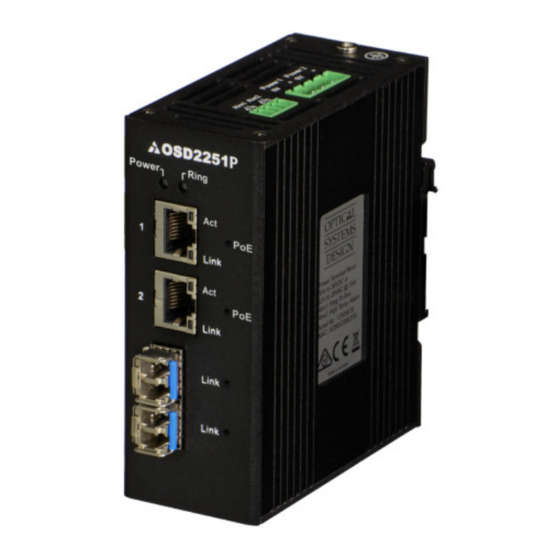
OPTICAL SYSTEMS DESIGN 1 TECHNICAL SUMMARY BRIEF DESCRIPTION 1.1.1 OVERVIEW The OSD2251BP is a 4-port industrial switch with redundant ring Gigabit Ethernet and PoE++ Source providing simple network management with real-time monitoring. It has two 10/100/1000Base-T RJ45 copper ports and two SFP ports for ring/bus configuration. -
Page 6: Features And Benefits
OPTICAL SYSTEMS DESIGN 1.1.2 APPLICATIONS ▲ Any network utilising a mix of copper ▲ Networks using Power over Ethernet and fiber devices such as cameras, intercoms, access control, telephones, etc. ▲ Industrial IP communications ▲ Self-healing Gigabit Ethernet backbone networks 1.1.3... -
Page 7: Technical Specifications
OPTICAL SYSTEMS DESIGN TECHNICAL SPECIFICATIONS TABLE 1: TECHNICAL SPECIFICATIONS SPECIFICATION PERFORMANCE IEEE802.3i/802.3u/802.3ab/802.3af/802.3at, 10/100/1000Base-T Ethernet Electrical Data Interface Electrical Data Rate 10, 100, 1000Mbps with energy detect, auto negotiate, auto MDIX 10KB Jumbo Frame Support IEEE802.3z 1000Base-Lx/Sx or IEEE802.3u 100Base-Fx Optical Data Interface... -
Page 8: Port Allocation
OPTICAL SYSTEMS DESIGN PORT ALLOCATION Front Panel: There are two fixed copper ports for 10/100/1000Base-T and two SFP ports. Top Panel: The top panel consists of a 4-way 5.08mm terminal block power connector and a 4-way 3.5mm terminal block alarm connector. -
Page 9: Installation
OPTICAL SYSTEMS DESIGN 2 INSTALLATION AND OPERATION INTRODUCTION This section outlines the methods required to install and operate the OSD2251BP successfully. It should be studied carefully if damage to the equipment or poor results are to be avoided. This equipment has been fully tested prior to dispatch and is ready for immediate operation. However it is advisable to check for external transportation damage before operation. -
Page 10: Drawings And Dimensions
OPTICAL SYSTEMS DESIGN 2.2.2 DRAWINGS AND DIMENSIONS The OSD2251BP is designed to be surface mounted or wall mounted onto a DIN-Rail (35mm top hat) fixture. The unit dimensions (excluding connectors, SFPs, etc) is shown in Figure 3 below; 110mm 91mm... -
Page 11: Power Supply Connections
OPTICAL SYSTEMS DESIGN 2.2.3 LOCATION The OSD2251BP should be placed where it will not be subjected to extreme temperatures, humidity, or electromagnetic interference. Specifically, the site selected should meet the following requirements: • The ambient temperature should be between -20°C to 75°C. -
Page 12: Alarm Connection
OPTICAL SYSTEMS DESIGN 2.2.5 ALARM CONNECTION The OSD2251BP has two monitoring alarm outputs: 1) Ring to Bus Alarm and 2) Temperature Alarm. The alarm connections and conditions for alarm outputs are as set out in Table 3. There are four pins on the 3.5mm terminal block used alarm output. -
Page 13: Usb Connector
OPTICAL SYSTEMS DESIGN 2.2.6 USB CONNECTOR The OSD2251BP has a USB – Type B connector located on the bottom of the unit that is used for Command Line Interface (CLI) from the PC to the OSD2251BP via the PC’s USB connector. See section 2.5 for further CLI information. -
Page 14: Led Indicators
OPTICAL SYSTEMS DESIGN 2.2.7 LED INDICATORS FIGURE 9: LED INDICATORS TABLE 4: LED FUNCTION Function LED Colour Function Blink Green Gr/Am Amber Power No Power Unmanaged Ring/Bus Initial Mode/ Ring Initializing Programming Activity No Activity 1Gbps/100Mbps Load No Load Detect... - Page 15 OPTICAL SYSTEMS DESIGN 2.2.8 CONTROLS The OSD2251BP has an 8-way DIP switch to control a number of functions. Table 5 outlines the function of each switch. FIGURE 10: SWITCH CONTROLS FIGURE 11: 8-WAY DIP SWITCH TABLE 5: 8-WAY DIP SWITCH SETTINGS...
-
Page 16: Fitting Sfp Connectors
OPTICAL SYSTEMS DESIGN 2.2.9 FITTING SFP CONNECTORS Care should be taken when inserting/removing the SFP connectors from SFP port 3 and 4as SFP modules are Electrostatic (ES) sensitive and Electrostatic Discharge (ESD) precautions should be taken when installing. Ensure that the SFP is fully engaged and latched into position. -
Page 17: Operation
OPTICAL SYSTEMS DESIGN OPERATION When using the OSD2251BP for the first time, check that the unit is in good condition with no visible damage. Upon power up check that the indicators illuminate accordingly on power up (see Table 4). 2.3.1 CONNECTIONS For RJ45 connection use Category 5 (CAT5) or higher. - Page 18 OPTICAL SYSTEMS DESIGN To connect the OSD2251BP in a redundant ring configuration ports 3 and 4 must be used together with fiber SFPs. The non-ring ports (ports 1 & 2) should be used to connect to your Ethernet devices (eg.
-
Page 19: Mini Usb Port
OPTICAL SYSTEMS DESIGN MINI USB PORT The Mini USB Port is used for uploading firmware updates. All OSD2251BP units will be shipped with the latest firmware already installed. This port has no function for end user. Mini USB Port FIGURE 16: MINI USB CONNECTOR... -
Page 20: Command Line Interface
OPTICAL SYSTEMS DESIGN COMMAND LINE INTERFACE The Command Line Interface (CLI) is a useful tool for checking link status and debugging link connections. To enable the use of CLI the OSD2251BP must be connected to a PC with a serial port and an appropriate cable as specified in section 2.2.6. -
Page 21: Command Line Functions
OPTICAL SYSTEMS DESIGN 2.5.2 COMMAND LINE FUNCTIONS There are a number of command line functions that enables the user to obtain running information of a single OSD2251BP unit or the complete topology of the ring/bus network. This section explains the command lines and its functions. -
Page 22: Version Check
OPTICAL SYSTEMS DESIGN VERSION CHECK - <vc> FIGURE 18: VERSION CHECK Displays the Software Version Number and Software ID Number installed on the OSD2251BP DOC ID: 10119301 PAGE 22 OSD2251BP OPERATOR MANUAL... -
Page 23: Default Setting
OPTICAL SYSTEMS DESIGN DEFAULT SETTING - <ds> FIGURE 19: DEFAULT SETTING Resets the OSD2251BP to its default factory setting. A prompt question will appear “Do you want to Reset Configuration [y/n]? n – Exits the default configuration setting and returns to the home prompt. - Page 24 OPTICAL SYSTEMS DESIGN IP CONFIGURATION - <ipconfig> FIGURE 20: IP CONFIGURATION Displays the current IP address, Net mask and Gateway settings. To make changes to the IP address, Net mask and Gateway, at the prompt enter the new details in the following format;...
- Page 25 OPTICAL SYSTEMS DESIGN TOPOLOGY CHECK - <tc> FIGURE 21: TOPOLOGY CHECK In this case, only one OSD2251BP is connected to the USB cable. The display indicates the following; No: 1 – Number of units connected on the ring/bus (in this case only one unit) MAC_ADDRESS: 00:26:dc:00:1e:28 –...
- Page 26 OPTICAL SYSTEMS DESIGN In the example below there are four OSD2251BP connected in a ring configuration. FIGURE 22: TOPOLOGY CHECK No: 4 – Four units connected MAC_ADDRESS:– Displaying all the MAC addresses of the units connected on the ring/bus TOPOLOGY: Ring – Displaying type of connection.
- Page 27 OPTICAL SYSTEMS DESIGN NODE CHECK - <nc> FIGURE 23: NODE CHECK Node check obtains the running status of the node for the specific MAC address requested within the Ring/Bus. Correct entry format is as follows (MAC address specified below is an example);...
- Page 28 OPTICAL SYSTEMS DESIGN LOCAL NODE CHECK - <lnc> FIGURE 24: LOCAL NODE CHECK This command line displays the running status of the local node that the USB cable is plugged into. The information provided is the MAC address, Topology, Node Role, Port Role and Float Backup status.
- Page 29 OPTICAL SYSTEMS DESIGN FLOAT BACKUP ENABLE <fbe> FIGURE 25: FLOAT BACKUP ENABLED 1 No: 4 – Lists number of units connected (in this case 1,2,3,4) MAC_ADDRESS:– Displaying all the MAC addresses of the units connected on the ring/bus FLOAT_BACKUP: Enable – Displays all the units connected to the ring/bus having Float Backup enabled.
- Page 30 OPTICAL SYSTEMS DESIGN In Figure 26, node 1 will communicate with node 2, node 3 and node 4 via node 3. Node 2 will communicate to node 4 only via node 1 and 3. In the event of a fiber link being broken or disconnected (indicated by a cross) the backup branch will become the active branch.
- Page 31 OPTICAL SYSTEMS DESIGN FLOAT BACKUP DISABLE - <fbd> FIGURE 29: FLOAT BACKUP DISABLED 1 No: 4 – Lists number of units connected (in this case 1,2,3,4) MAC_ADDRESS:– Displaying all the MAC addresses of the units connected on the ring/bus FLOAT_BACKUP: Disable – Displays all the units connected to the ring/bus having Float Backup disabled.
- Page 32 OPTICAL SYSTEMS DESIGN In the event of a fiber link being broken or disconnected (indicated by a cross) the backup branch will become the active branch. If the link between node 1 and 3 is broken (see Figure 30), node 1 will communicate with node 3 via node 2 and node 4.
- Page 33 OPTICAL SYSTEMS DESIGN NODE IP SET - <node_ip_set> FIGURE 32: NODE IP SET This command line enables the user to setup the IP of the node with the given MAC address. Correct entry format is as follows (MAC, IP, mask and gateway address specified below is an example);...
- Page 34 OPTICAL SYSTEMS DESIGN REBOOT - <reboot/rb> FIGURE 34: REBOOT This command line enables the user to reboot the device either locally or remotely. Note: Rebooting should ONLY be used when network failure occurs. Rebooting a properly running network is not advised as network operation may cease.
- Page 35 OPTICAL SYSTEMS DESIGN WEB GUI The OSD2251BP provides a web-based browser interface for configuring and monitoring the unit. This interface allows you to access the switch using any preferred web browser. This chapter describes how to configure the switch using its web-based browser interface.
-
Page 36: Logging On To The Switch
OPTICAL SYSTEMS DESIGN 2.6.1 LOGGING ON TO THE SWITCH IP A WITCH DDRESS In your web browser, specify the IP address of the switch. Default IP address is 192.168.0.99 Upon connecting to the OSD2251BP, the home screen will display some useful information. The header will display the OSD2251BP configuration (60W or 90W). - Page 37 OPTICAL SYSTEMS DESIGN 2.6.2 GUI MENU The user has access to Configure, Monitor or Maintain the OSD2251BP. Each section will be explained within this manual. DOC ID: 10119301 PAGE 37 OSD2251BP OPERATOR MANUAL...
- Page 38 OPTICAL SYSTEMS DESIGN ONFIGURATION YSTEM IP A DDRESS Configured: The IP address can be changed by modifying this window. Current: Displays the current saved IP address UBNET Configured: The Subnet Mask can be changed by modifying this window. Current: Displays the current saved Subnet Mask...
- Page 39 OPTICAL SYSTEMS DESIGN ONFIGURATION Indicates port number per row. NABLED A tick indicates the PoE is enabled for the port. ANUAL OWER IMITATION NABLED Allows the user to manually limit power in Watts (W) to each individual port. A tick indicates that the Manual Power Limitation is enabled.
- Page 40 OPTICAL SYSTEMS DESIGN ONFIGURATION ETTING Indicates the Port number Allows the user to set the Port Speed from the drop-down selection. • Auto: Auto detection of the port speeed • 10Mbps HDX: 10Mbps Half Duplex mode • 10Mbps FDX: 10Mbps Full Duplex mode •...
- Page 41 OPTICAL SYSTEMS DESIGN ONITOR YSTEM ONITOR Monitors each port activity. /SFP OPPER Indicates the port connection: Either Copper or SFP Switch Port: Indicates the role of the port Ring Port: Indicates the role of the port Up: Connection established Down: No Connection detected PEED Indicates the port connection speed in Mbps.
- Page 42 OPTICAL SYSTEMS DESIGN ONITOR OPOLOGY Indicates number of units connected to the ring/bus MAC A DDRESS Lists the MAC address of the individual units connected on the ring/bus OPOLOGY Indicates type of connection of the system • Init: Only single unit connected •...
- Page 43 OPTICAL SYSTEMS DESIGN ONITOR Indicates port number per row. HANNEL Indicates the channel number of the port • Ch0: Pins 1,2 and Pins 3,6 on RJ45 • Ch1: Pins 4,5 and Pins 7,8 on RJ45 URRENT Indicates the current drawn from the relevant PoE port/channel...
- Page 44 OPTICAL SYSTEMS DESIGN ONITOR Monitors and logs activity Event number Records a time-stamp of the log activity A brief description of the type of event AINTANANCE PLOAD Use this section to upload OSD released update software. Buttons : Browse file location...
-
Page 45: External Inspection
OPTICAL SYSTEMS DESIGN 3 MAINTENANCE INTRODUCTION The following section outlines the fault-finding procedure for the OSD2251BP modems. Please take note of the following: ▲ Personnel without appropriate training should not attempt any maintenance except that outlined below. ▲ If further maintenance is attempted you are warned that every care should be taken to ensure that... -
Page 46: Warranty Period
For warranty period, please contact your local OSD distributor. REPAIRS Optical Systems Design reserves the right to repair or replace faulty modules/units. Please obtain a “Return Material Authorisation” (RMA) form and number before returning goods. Goods must be returned in adequate packing material to Optical Systems Design, Warriewood or its nominated authorised representative, for all repairs. - Page 47 OPTICAL SYSTEMS DESIGN DOC ID: 10119301 PAGE 47 OSD2251BP OPERATOR MANUAL...
- Page 48 Optical Systems Design Pty. Ltd. OPTIC L 7/1 Vuko Pl. Warriewood 2102 P.O. Box 891 Mona Vale N.S.W. Australia 2103 SYSTEMS Telephone: +61 2 9913 8540 Facsimile: +61 2 9913 8735 Email: sales@osd.com.au DESIGN Web Site: www.osd.com.au PTY LTD A.B.N. 83 003 020 504...
Need help?
Do you have a question about the OSD2251BP Series and is the answer not in the manual?
Questions and answers