
Related Manuals for Optical Systems Design OSD2054P Series


Summary of Contents for Optical Systems Design OSD2054P Series
-
Page 1: Index
OPERATOR MANUAL OSD2054P SERIES 10/100Base-T to 100Base-X 3-PORT SWITCH with PoE SOURCE... -
Page 3: Table Of Contents
OPTICAL SYSTEMS DESIGN INDEX 1 TECHNICAL SUMMARY ......................4 BRIEF DESCRIPTION ......................4 1.1.1 OVERVIEW ......................... 4 1.1.2 APPLICATIONS ........................4 1.1.3 FEATURES AND BENEFITS ..................... 4 TYPICAL CONFIGURATION ....................5 TECHNICAL SPECIFICATIONS ................... 6 OSD2054P FRONT AND REAR PANELS ................7 INSTALLATION AND OPERATION .................. -
Page 4: Technical Summary
OPTICAL SYSTEMS DESIGN 1 TECHNICAL SUMMARY BRIEF DESCRIPTION 1.1.1 OVERVIEW The OSD2054P is designed to convert between 10/100Base-T copper cabling and 100Base-X fiber cabling. It has two RJ45 copper ports one of which supports PoE and one SFP port which can be specified by the user for one or two fiber configuration. -
Page 5: Typical Configuration
OPTICAL SYSTEMS DESIGN TYPICAL CONFIGURATION Figure 1 below indicates the typical set-up for an OSD2054P system. FIGURE 1: OSD2054P TYPICAL CONFIGURATIONS DOC ID: 10116001 PAGE 5 OSD2054P OPERATOR MANUAL... -
Page 6: Technical Specifications
OPTICAL SYSTEMS DESIGN TECHNICAL SPECIFICATIONS TABLE 1: TECHNICAL SPECIFICATIONS SPECIFICATION PERFORMANCE IEEE802.3 Ethernet Electrical Data Interface Electrical Data Rate 10/100Mbps Half or Full Duplex Operating Mode RJ45, the PoE unit mounted on the front panel and the non-PoE unit on the rear... -
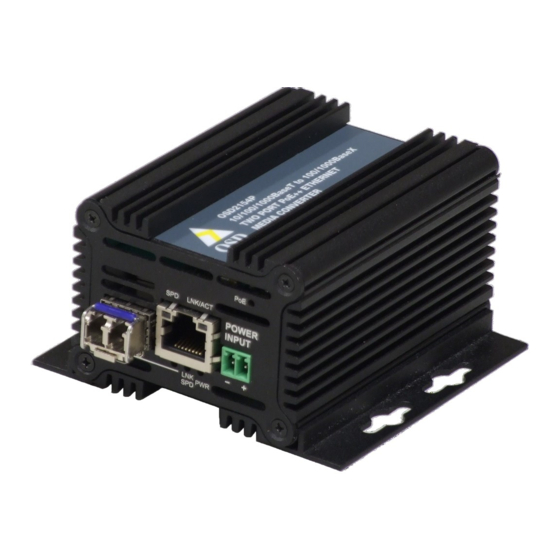
Page 7: Osd2054P Front And Rear Panels
OPTICAL SYSTEMS DESIGN OSD2054P FRONT AND REAR PANELS There are two fixed 10/100Mbps RJ45 copper ports: the PoE located on the front panel and non-PoE on the rear panel. The SFP port and 2-way term-block power connector are also located on the front panel. -
Page 8: Installation And Operation
OPTICAL SYSTEMS DESIGN 2 INSTALLATION AND OPERATION INTRODUCTION This section outlines the methods required to install and operate the OSD2054P successfully. It should be studied carefully if damage to the equipment or poor results are to be avoided. This equipment has been fully tested prior to dispatch and is ready for immediate operation. However it is advisable to check for external transportation damage before operation. -
Page 9: Osd2054P Drawings And Dimensions
OPTICAL SYSTEMS DESIGN 2.2.2 OSD2054P DRAWINGS AND DIMENSIONS The standard OSD2054P is designed to be mounted on an even surface and to be secured by means of M4 or smaller screws. All dimensions are in mm. The unit also can be mounted on a standard DIN rail with the OSD2054P DIN Rail bracket. -
Page 10: Power Supply Connections
OPTICAL SYSTEMS DESIGN 2.2.3 POWER SUPPLY CONNECTIONS The OSD2054P requires external DC power. The voltage range of the OSD2054P is +10V +36V and for the OSD2054P/48V is +47V to +57V . Power should be connected to the 2-way terminal block located on the front panel as indicated in Table 2. -
Page 11: Led Indicators
OPTICAL SYSTEMS DESIGN 2.2.5 LED INDICATORS Front Panel Rear Panel FIGURE 7: LED INDICATORS TABLE 3: LED FUNCTION FUNCTION Indicator LED Colour Blinking PoE Active Green No PoE Copper Speed: Green 10/100Mbps Power On Green Power Off LNK/ACT Copper Link Activity... -
Page 12: Fitting Sfp Connectors
OPTICAL SYSTEMS DESIGN 2.2.6 FITTING SFP CONNECTORS Care should be taken when inserting/removing the SFP connectors from the SFP port as SFP modules are Electrostatic (ES) sensitive and Electrostatic Discharge (ESD) precautions should be taken when installing. Ensure that the SFP is fully engaged and latched into position. -
Page 13: Maintenance
OPTICAL SYSTEMS DESIGN 3 MAINTENANCE INTRODUCTION The following section outlines the fault-finding procedure for the OSD2054P modems. Please take note of the following: Personnel without appropriate training should not attempt any maintenance except that outlined ▲ below. If further maintenance is attempted you are warned that every care should be taken to ensure that ▲... -
Page 14: Warranty
For warranty period, please call your local OSD distributor. REPAIRS Optical Systems Design reserves the right to repair or replace faulty modules/units. Please obtain a “Return Material Authorisation” (RMA) form and number before returning goods. Goods must be returned in adequate packing material to Optical Systems Design, Warriewood, NSW, Australia or its nominated authorised representative, for all repairs. - Page 15 OPTICAL SYSTEMS DESIGN DOC ID: 10116001 PAGE 15 OSD2054P OPERATOR MANUAL...
- Page 16 OPTIC L Optical Systems Design Pty. Ltd. 7/1 Vuko Pl. Warriewood 2102 SYSTEMS P.O. Box 891 Mona Vale N.S.W. Australia 2103 Telephone: +61 2 9913 8540 DESIGN Facsimile: +61 2 9913 8735 Email: sales@osd.com.au Web Site: www.osd.com.au PTY LTD A.B.N. 83 003 020 504...
Need help?
Do you have a question about the OSD2054P Series and is the answer not in the manual?
Questions and answers