
Related Manuals for Phenix Technologies HC-75C


Summary of Contents for Phenix Technologies HC-75C
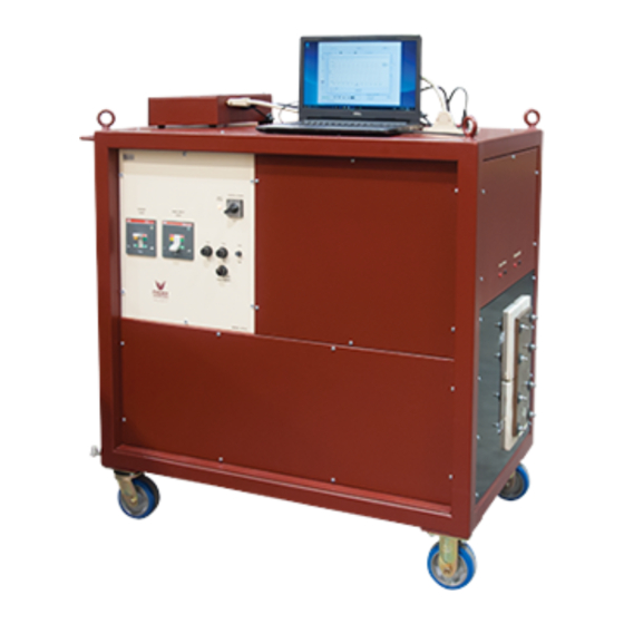
- Page 1 AC CIRCUIT BREAKER TEST SET OPERATOR’S MANUAL Version 3.1 MODEL HC-75C (480V) SERIAL NUMBER: Phenix Technologies, Inc. 75 Speicher Drive Accident, MD 21520 USA Copyright © Phenix Technologies, Inc. Rev 1/18/2018 jsh HC 75C...
- Page 2 AC CIRCUIT BREAKER TEST SET Model Number HC 75C Serial Number Customer Customer's Purchase Order Number Manufacturing Date HC 75C...
-
Page 3: Table Of Contents
TABLE OF CONTENTS SECTION NUMBER TITLE PAGE DANGER / GENERAL SAFETY PRECAUTIONS SPECIFICATIONS INTRODUCTION SAFETY INSTALLATION INSTRUCTIONS POWER ON / OFF PROCEDURE POWER SECTION DESCRIPTION TESTING PROCEDURE TROUBLESHOOTING SERVICE AND MAINTENANCE CALIBRATION OF CIRCUIT BREAKER TEST SETS WinHC PC SOFTWARE ELECTRICAL SCHEMATICS CIRCUIT DIAGRAM SYMBOLS PARTS LIST... - Page 4 SECTION 1: DANGER / WARNINGS WARNING !! Complete Grounding of this unit is necessary for the safe operation of this equipment. Disconnect inputs before ungrounding this equipment. HC 75C...
-
Page 5: Danger / General Safety Precautions
DO NOT operate damaged equipment. Remove power, and do not use the equipment until safe operation can be verified by service-trained personnel. Phenix Technologies, Inc. assumes no liability for unsafe or improper use of test equipment. HC 75C... -
Page 6: Specifications
(Note: The above current levels are based on the 30 minute duty cycle. To estimate the current draw on the facility power at different duty cycles, multiply the above currents by the ratio of the output currents. Ex.: An HC-75C will draw approximately 7.5 times the above current at the 1 second duty cycle.) Output:... - Page 7 SPECIFICATIONS Instrumentation: Currentmeter: Resolution: 0.1% of Full Scale Ranges: 100/1000/10,000/100,000 Amps Accuracy: 0.8% rdg + 0.3% range ± 5% of Full Scale 0.02 – 0.10 Seconds Timer: Resolution: 0.002 Seconds 0.120 Cycles Ranges: 0 - 999.999 Seconds 0 - 99,999.990 Cycles Test durations of less than 10 cycles Timer Accuracy: ±...
-
Page 8: Introduction
SECTION 3: INTRODUCTION Phenix Technologies' High Current Test Sets represent a new era of electrical testing technology. This design is based on time-proven concepts and the power offered by an embedded 32-bit microcomputer. High reliability Semiconductor Controlled Rectifiers (SCRs) have been combined with a phase angle firing system to deliver precisely repeatable current pulses with minimal distortion. -
Page 9: Safety
SECTION 4: SAFETY Several safeguards have been built into the Phenix Technologies high current test sets; however, these safeguards are only effective if safe work practices are also used. The test set and these procedures have been designed for use by knowledgeable electrical workers who have been properly trained in its use. -
Page 10: Installation Instructions
SECTION 5: INSTALLATION INSTRUCTIONS Position the test set in the desired position. For 2-cabinet units, place the regulator cabinet on top of the transformer cabinet. The following procedure is only required for 2-cabinet units (HC-12C and HC-20C): Connect the interconnect ground cable from the regulator cabinet to the transformer cabinet. -
Page 11: Power On / Off Procedure
SECTION 6: POWER ON / OFF PROCEDURE Ensure proper connection of the test set and its components as described in the Installation Instructions, Section 5. Ensure that CB201, CB202 and the CONTROL POWER switch (SW201) are in their OFF positions. Energize the facility power distribution breaker. -
Page 12: Power Section Description
SECTION 7: POWER SECTION DESCRIPTION Fuses and Circuit Breakers The single phase input power enters the regulator through CON202 and CON203 and is immediately connected to CB201. Circuit breaker CB201 protects the main power section and is equipped with an under-voltage release coil. - Page 13 SECTION 7: POWER SECTION DESCRIPTION Taps and Variable Transformer To achieve a variable output from minimum to maximum, a system of taps and a motorized variable transformer is employed. The tap selects the coarse range of the output and the variable transformer controls the output from the ‘top’...
- Page 14 POWER SECTION DESCRIPTION The following is a brief description of the various parts of the HC test set. HC Controller Performs all monitoring and control functions for the HC Test Set. Input Power Indicator, Indicates that Input Power is applied to the test set. LMP201 Control Power Switch, Applies 120-Volt AC Power to all of the controls in the test set.
-
Page 15: Testing Procedure
SECTION 8: TESTING PROCEDURE WARNING: To ensure safe operation, breaker CB201 should be opened prior to any connections being made to the output stabs on the test set. CB201 may then be closed after the connections are complete. FACTORY SETTINGS The following chart shows the factory settings. - Page 16 TESTING PROCEDURE BASIC OPERATION These steps should be followed to test a circuit breaker after the POWER ON procedure in Section 6: Ensure that the test set’s main circuit breaker, CB201, is open. Connect the breaker under test to the output of the test set. Ensure the output is configured correctly (either Parallel or Series connection) and the WinHC connection setting matches the configuration.
- Page 17 Click Settings in Test Parameters. Enter the number of cycles that the output will be energized. This should be long enough to get a good reading, but short enough to avoid overheating. Phenix Technologies recommends a value of 7 cycles.
- Page 18 This should be long enough to get a good reading and at least twice the expected instantaneous trip time, but short enough to avoid overheating. Phenix Technologies recommends a value of 7 cycles. Be sure to click OK to record the setting.
- Page 19 TESTING PROCEDURE JOG to HOLD MODE After performing the steps under BASIC OPERATION, follow the steps to perform the Jog to Hold function. Click Settings in Test Parameters: Enter the desired output current set-point. This is the current that the test set will ‘jog’ to. Click Settings in Test Parameters: Enter the number of cycles that the output will be energized.
- Page 20 TESTING PROCEDURE CURRENT HOLD MODE After performing the steps under BASIC OPERATION, follow the steps below to perform the Current Hold function. Although this continuous mode of operation is possible, the recommended method for reaching a HOLD current is to use the JOG to HOLD function. Click Settings in Test Parameters: Enter the desired output current set point.
-
Page 21: Troubleshooting
SECTION 9: TROUBLESHOOTING If the unit is suspected to be malfunctioning, refer to the following guide for testing the unit and isolating the problem. Some minor repairs can be made in the field. Otherwise, call the factory for assistance. WARNING! SOME TROUBLESHOOTING PROCEDURES REQUIRE OPENING THE TEST SET, WHICH HAS POTENTIALLY LETHAL VOLTAGES ON EXPOSED CONDUCTORS. -
Page 22: Service And Maintenance
10-1 SECTION 10: SERVICE AND MAINTENANCE Periodic Maintenance The following maintenance should be performed about once a year, unless otherwise indicated below, to ensure that the test set maintains proper output and operation. Units that are used and transported often should have shorter maintenance intervals. -
Page 23: Calibration Of Circuit Breaker Test Sets
11-1 SECTION 11: CALIBRATION OF CIRCUIT BREAKER TEST SETS (Models HC-8C through HC-75C) Calibration of this series of HC’s must be performed with the laptop computer. The following items will be required to perform the calibration. 1. A laboratory “benchtop” multimeter a. - Page 24 11-2 CALIBRATION Before adjustment you should document the current Cal Factors for record keeping. Connect the standard CT with cables rated for the current you need to apply as if running a breaker. NOTE: Make sure the top two plates and the bottom two plates are shorted. (Parallel Mode) Use your Stabs or copper bars for this connection.
- Page 25 11-3 CALIBRATION Calibrate Voltmeter The voltmeter calibration functions the same as the current meter calibration. Before adjustment you should document the current Cal Factors for record keeping. For this calibration you will inject voltages into the banana jacks over the output panel. (NOT CONTINUITY BINDING POSTS) Raise the voltage source to approximately 80% of range.
- Page 26 11-4 CALIBRATION Restore Calibration Factors: It is recommended that documentation of the cal factors be maintained, in the event that the cal factors become corrupt or if inadvertently changed and need to be restored. This can be done by going to the Hardware Settings screen.
-
Page 27: Winhc Pc Software
SECTION 12: WinHC PC SOFTWARE About WinHC Welcome to WinHC, circuit breaker test system software developed by Phenix Technologies to control the Phenix Technologies high current test sets. WinHC provides advanced database and report generation capabilities, enabling you to save your circuit breaker test results in a database for future recall and report generation. - Page 28 12-2 WinHC PC SOFTWARE Using WinHC WinHC main screen Navigating WinHC is made easy by the navigation buttons. These buttons are always accessible and located on the heading bar of every screen. These buttons provide access to the major areas of WinHC: Test, Results, and Options.
- Page 29 12-3 WinHC PC SOFTWARE Tap: Selects the output tap. Higher taps produce a higher output voltage and therefore higher current. Current Range: Selects the range on the current meter. Note: The current meter may auto-range upward when the current level exceeds the current range. Start/Stop: Initiates and halts a test.
- Page 30 12-4 WinHC PC SOFTWARE Performing a Circuit Breaker Test The following is the step-by-step procedure for using WinHC to test a circuit breaker, save the results in the database and generate a test report. 1. On the Nameplate Data screen, click New Job…. Enter the Serial Number of the unit you are about to test then click Ok, or use the pull-down menu to select a recently tested serial number.
- Page 31 12-5 WinHC PC SOFTWARE 4. Repeat step 3 for each phase and test level that you wish to test. 5. Click Notes... to add any test notes. 6. Click Report... to generate a test report. Generating Reports The WinHC software keeps a history of all circuit breaker and tests that have been performed. Here’s the procedure for creating test reports of previous tests.
- Page 32 12-6 WinHC PC SOFTWARE General Options Use these options to configure your test report and other generic options. Access these options by clicking the Options button on the main screen, then click the General tab. The General Options screen Company, Header1, Header2, Header3: These fields determine what text will appear at the top of reports.
- Page 33 12-7 WinHC PC SOFTWARE Labels The Labels Options Screen The labels options screen contains the field labels for the optional circuit breaker nameplate fields. You may change any of these to suit your particular needs. These labels appear on the circuit breaker nameplate screen, under Additional Info…, and on test reports.
- Page 34 12-8 WinHC PC SOFTWARE Use these options to maintain standard circuit breaker type and circuit breaker manufacturer lists. Items in these lists will appear in pull-down menus, off of the circuit breaker type and make fields. You may edit these lists to match your specific needs. Tests The Tests Options Circuit breaker Test Titles: You may customize the test titles to match your individual testing...
- Page 35 12-9 WinHC PC SOFTWARE Data Backup WinHC data should be backed up on a regular basis. Hard disks do fail, you don’t want to lose years of valuable data. We recommend that you maintain at least two separate backups. WinHC has backup and restore functions that make this an easy task.
- Page 36 12-10 WinHC PC SOFTWARE Data Recovery The Restore Data Screen Should something happen and you need to restore data from a backup, WinHC provides a similar function for restoring data. The restore data screen allows you to easily select a drive/directory as a source for your data recovery.
-
Page 37: Electrical Schematics
PCB 1389, HC Interface BD 31139100 PCB1391, HC Interconnect BD HC Regulator / Transformer Cabinet(s) Drawing Number Description 9304592 HC-75C Electrical Schematic 31115520 PCB 1155B, HC I/O Interface Schematic 31115600 PCB 1156, SCR Trigger Board 31125210 PCB 1252A, RMS-to-DC Converter... - Page 38 HC 75C...
-
Page 39: Circuit Diagram Symbols
14-1 SECTION 14: CIRCUIT DIAGRAM SYMBOLS HC 75C... - Page 40 15-1 SECTION 15: HC-75C (600V) PARTS LIST Phenix Part # Item Description CONTROLLER RIGHT ANGLE USB CABLE, 2’ 1001402 CABLE 101-104 1079908 CABLE 105-107 RIBBON CABLE 1152145 CABLE 37 PIN TO RIBBON 1152160 CABLE 40 PIN CONN 1152248 3CKT 1152590...
- Page 41 15-2 HC-75C (600V) PARTS LIST Phenix Part # Item Description REGULATOR AND HIGH CURRENT SECTION 38602282 T301 TRANSFORMER, HIGH CURRENT 1356214 BP201,3 BINDING POST, BLACK 1356215 BP202,4 BINDING POST, RED 1092590 C201 CAPACITOR 1099120 C202 CAPACITOR 1600609 CB201 CIRCUIT BREAKER...
- Page 42 15-3 HC-75C (600V) PARTS LIST Phenix Part # Item Description REGULATOR AND HIGH CURRENT SECTION (Cont’d) 1862115 SW202 SWITCH, MUSHROOM 1862905 SW202 SWITCH, NC 3860024C T201 TRANSFORMER, CONTROL POWER, 1KVA 1894415 T203 TRANSFORMER, 115:40VCT, 1A 1894438 T204 TRANSFORMER, 575/115 PT...
-
Page 43: Recommended Spare Parts
In order to maintain your set in full operating condition with a minimum of down time, the following spare parts should be kept on hand to avoid unnecessary phone calls, expensive modes of shipment, delays in repairs, etc. Pricing is available upon request from the Service Department at Phenix Technologies. Part Number... -
Page 44: Parts Ordering Information
When your purchase order is received at our office, a representative of Phenix Technologies will contact you to confirm the current price of the part being ordered. If a part you order has been replaced with a new or improved part, an Applications Engineer will contact you concerning any change in part number. -
Page 45: Returned Material
Serial Number Reason for Return Cause of Defect If Phenix Technologies, Inc. deems return of the part appropriate, it will then issue an "Authorization for Return." If return is not deemed advisable, other inspection arrangements will be made. NOTE: Material received at this plant without the proper authorization shall be held as "Customer's Property"... -
Page 46: Customer Comments / Suggestions
19-1 SECTION 19: CUSTOMER COMMENTS / SUGGESTIONS Phenix Technologies made significant efforts to ensure that the materials in this Operator’s Manual are correct. If there are concerns or comments as you have used this information, Phenix Technologies appreciates any feedback.
Need help?
Do you have a question about the HC-75C and is the answer not in the manual?
Questions and answers