
Subscribe to Our Youtube Channel
Related Manuals for Phenix Technologies HC2


Summary of Contents for Phenix Technologies HC2
- Page 1 USER’S MANUAL PORTABLE HIGH CURRENT TEST SET MODEL NUMBER HC2 Version 4.0 Phenix Technologies Inc. 75 Speicher Drive Accident, Maryland 21520 Copyright © Phenix Technologies, Inc. Rev 11/20/2014 nab HC-2...
-
Page 2: Table Of Contents
TABLE OF CONTENTS DESCRIPTION SECTION NUMBER DANGER / GENERAL SAFETY PRECAUTIONS TECHNICAL SPECIFICATIONS DEVICE WARNINGS CONTROLS AND INDICATORS BASIC APPROACH TO TESTING CALIBRATION PARTS LIST PARTS ORDERING INFORMATION RECOMMENDED SPARE PARTS RETURNED MATERIAL ELECTRICAL SCHEMATICS CUSTOMER COMMENTS / SUGGESTIONS HC-2... - Page 3 DANGER HC-2...
- Page 4 • DO NOT operate damaged equipment. Remove power, and do not use the equipment until safe operation can be verified by service-trained personnel. Phenix Technologies, Inc. assumes no liability for unsafe or improper use of test equipment. HC-2...
-
Page 5: Technical Specifications
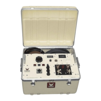
SECTION 1: TECHNICAL SPECIFICATIONS The HC2 is a portable high current test set built for field and shop use. Designed using the latest technology, the HC2 combines a variable high current output with appropriate controls and instrumentation for testing thermal, magnetic, and solid-state motor overload relays, molded-case circuit breakers, and ground fault trip devices. -
Page 6: Device Warnings
SECTION 2: DEVICE WARNINGS 1. For safe operation, it is important that the unit be plugged into a properly grounded receptacle. 2. This unit is not designed for use in energized circuits. 3. Due to leakage current within the solid-state circuitry, it is STRONGLY RECOMMENDED to turn control power off when changing the output leads. -
Page 7: Controls And Indicators
SECTION 3: CONTROLS AND INDICATORS [Insert drawing of unit control panel face here[ The following is a listing of the controls, switches, and lamps on the control panel and a description of their functions. MAIN POWER This circuit breaker controls the input power to the control and the power sections. OUTPUT This circuit breaker protects the variable transformer. - Page 8 CONTROLS AND INDICATORS SENSE SWITCH This can be set to CONTACTS or CURRENT mode. When placed in CONTACTS mode, the unit will react to a change in condition of the SENSE INPUTS. Upon a change in condition, the TIMER will stop running and the output current will cease to flow.
-
Page 9: Basic Approach To Testing
SECTION 4: BASIC APPROACH TO TESTING The HC2 is basically a continuously variable high current source, the magnitudes of which are dependent on the output tap that is selected. Please refer to the Technical Data and Specifications for the voltage and current ratings of the taps. -
Page 10: Calibration
SECTION 5: CALIBRATION TIMER The timer is run from a precision programmable oscillator and should never require calibration. CURRENTMETER The calibration of the currentmeter should be checked on a yearly basis. To do this, place the MEM/CONT switch in the CONT position. Place the range switch in the 2 AMP range. - Page 11 SECTION 6: HC-2 PARTS LIST ITEM PART NO. DESCRIPTION 1601395 CKT BRKR HOLE COVER (120V) CB1,CB2 1601330 30A 1P CKT BRKR 250V (CE) (120V) 1601317 15A 2P CKT BRKR 250V (CE) (220V) 1601315 15A 1P CKT BRKR 250V (CE) (220V) 1892206 CURRENT TRANS.
-
Page 12: Parts Ordering Information
When your purchase order is received at our office, a representative of Phenix Technologies will contact you to confirm the current price of the part being ordered. If a part you order has been replaced with a new or improved part, an Applications Engineer will contact you concerning any change in part number. -
Page 13: Recommended Spare Parts
If the unit will be operated at an isolated site for an extended period or will be subjected to unusual stresses, a larger quantity of parts should be stocked as spares. In such cases, contact Phenix Technologies for a recommendation. -
Page 14: Returned Material
Reason for Return Cause of Defect If Phenix Technologies, Inc. deems return of the part appropriate, it will then issue an "Authorization for Return." If return is not deemed advisable, other inspection arrangements will be made. NOTE: Material received at this plant without the proper authorization shall be held as "Customer's Property"... -
Page 15: Electrical Schematics
10-1 SECTION 10: ELECTRICAL SCHEMATICS Drawing Number Description 1. 9304510 HC-2 Electrical Schematic (120V) 2. 9304511 HC-2 Electrical Schematic (220V) HC-2... -
Page 16: Customer Comments / Suggestions
11-1 SECTION 11: CUSTOMER COMMENTS/SUGGESTIONS Phenix Technologies made significant efforts to ensure that the materials in this Operator’s Manual are correct. If there are concerns or comments as you have used this information, Phenix Technologies appreciates any feedback. Unit Serial Number.
Need help?
Do you have a question about the HC2 and is the answer not in the manual?
Questions and answers