
Related Manuals for Phenix Technologies PM15-2


Summary of Contents for Phenix Technologies PM15-2
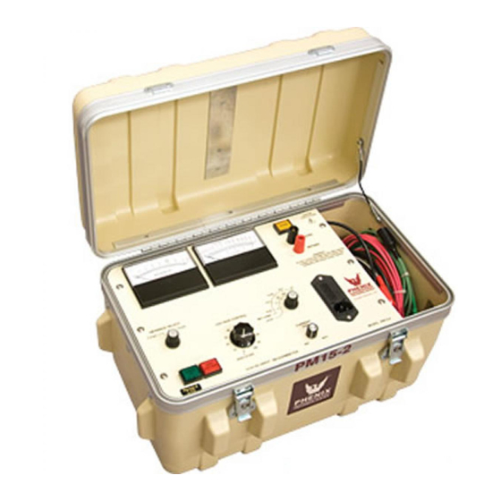
- Page 1 OPERATIONS AND APPLICATIONS MANUAL MODEL NUMBER PM15-2/PM15-4 15 kV DC HIGH POTENTIAL TESTER WITH MEGOHMMETER Version 1.0...
-
Page 3: Table Of Contents
TABLE OF CONTENTS Section Number DANGER PRODUCT INFORMATION -SAFETY AND CAUTION NOTES -DESCRIPTION -SPECIFICATIONS CONTROLS AND CONNECTIONS -FRONT PANEL CONTROLS AND METERS -INPUT/OUTPUT CONNECTIONS SET UP AND OPERATION INSTRUCTIONS -INSTALLATION -TEST LEAD CONNECTIONS -OPERATION SCHEMATIC PARTS LIST PARTS ORDERING INFORMATION RETURNED MATERIAL... - Page 4 DO NOT operate damaged equipment. Remove power, and do not use the equipment until safe operation can be verified by service-trained personnel. Phenix Technologies, Inc. assumes no liability for unsafe or improper use of test equipment.
-
Page 5: Product Information
DESCRIPTION The PM15-2/PM15-4 unit is capable of producing regulated voltages as high as 15 kV DC into a variety of insulated electrical apparatus. The unit will measure leakage current flow through (or insulation resistance levels of) the ground insulation of the test sample. Leakage current as low as .01 microamperes DC and as high as 2,000 microamperes (4,000A - PM15-4) DC can be... -
Page 6: Specifications
120 Volts AC, 50/60 Hz, single phase, 1 Amp 220 Volts AC, 50/60 Hz, single phase, .5 Amps Output: Regulated 0-15 kV DC, continuously adjustable with manual control. 0-2mA (PM15-2) 0-4mA (PM15-4) Negative Output, Positive Ground Voltmeter: 2%, 3.5”, analog meter, 0-7.5/15 kV Currentmeter/Megohmmeter: 2%, 3.5”, analog meter,... -
Page 8: Controls And Connections
The currentmeter range is selected by the five position rotary switch. The switch setting indicates the full scale current of the currentmeter and the megohmmeter multiplier. The table below shows the full scale currentmeter range with each switch setting. Switch Setting Currentmeter Ranges PM15-2 PM15-4 .5 microamps 0-.5 microamps 0-.5 microamps... - Page 9 10 – 1,000 M 20 – 2,000 M 30 - 3,000 M 2.5 – 100 M 5 – 200 M 7.5 – 300 M (PM15-2) 1.25 – 100 M 2.5 – 200 M 3.75 – 300 M (PM15-4) Voltmeter Range: This two position rotary switch scales the DC kilovolt meter.
-
Page 10: Input/Output Connections
CONTROLS AND CONNECTIONS INPUT/OUTPUT CONNECTIONS Return: Leakage current or insulation resistance values associated with this terminal is measured by the “DC Microammeter”. The low potential side of the test specimen should be connected to this terminal (red cable provided). When guard is not activated (switch not depressed), the return terminal is connected internally to ground. -
Page 11: Set Up And Operation Instructions
SET UP AND OPERATION INSTRUCTIONS SET UP Set up the unit as follows: 1. Turn the main “Power” switch off (push button out position, non-illuminated). 2. Turn the “High Voltage” power switch off (push button out position, non-illuminated). 3. Make necessary grounding connections. 4. - Page 12 SET UP AND OPERATION INSTRUCTION TEST LEAD CONNECTIONS (continued) 3. Any current flowing through the test lead attached to the “Return” terminal on the unit will always be measured by the “DC Microammeter” if the “Guard” switch is activated (illuminated), unless the specimen return is not isolated from ground in which case the currentmenter will be inoperative.
- Page 13 SET UP AND OPERATION INSTRUCTIONS OPERATION (continued) Example: If 2kV is read on the voltmeter and you are drawing 50 A, the resistance would be 40 megohms. 2000V Formula: 40,000,000 .00005A NOTE: Be sure that the “Guard” switch is in the desired position. Certain test conditions may require that leakage currents associated with the “Ground”...
- Page 14 SET UP AND OPERATION INSTRUCTIONS NOTES CONCERNING THE USE GUARD AND GROUND NORMAL MODE CONFIGURATION In this configuration the Return and Ground is connected together with an external jumper or a switch internal to the Test Set, depending on the design. Nothing is connected to the Guard. Both stray leakage to earth ground and leakage through the Test Specimen is indicated on the current meter.
- Page 15 SET UP AND OPERATION INSTRUCTIONS GUARD MODE CONFIGURATION In this configuration the Guard and Ground is connected together with an external jumper or a switch internal to the Test Set, depending on the design. Any current associated with the Return is indicated on the current meter.
-
Page 16: Schematic
SCHEMATIC Drawing Number Description 9109080 PM15-2... -
Page 17: Parts List
Lead, Return Test (Red) w/Insulated Clip 30080005 LEAD Lead, Ground (Black), w/Insulated Clip HIGH VOLTAGE COMPONENTS 1748200 Resistor, 6W, 75M 1590171 H.V. POWER Ultravolt 15A24-N30-E- Power Supply, 15kV-2mA (PM15-2) SUPPLY T0B6 1590174 H.V. POWER Power Supply, 15kV-4mA (PM15-4) Ultravolt 15C24-N60-E- SUPPLY T0B6 ELECTRICAL PARTS/COMPONENTS Module, Power Entry –... - Page 18 PM15-2/PM15-4 PARTS LIST continued N.P.N. R36 KNOB Knob, Raise Voltage Phenix 1860260 Switch, Main Power, Lighted, Latching 1 Pole EAO 31-261 1860265 Switch, Guard, Lighted, Latching 2 Pole EAO 31-262 1355310 SW3,SW4 Knobs for Voltmeter, Currentmeter Range KNOBS Switches 1863040...
- Page 19 PM15-2/PM15-4 PARTS LIST continued 1722300 Resistor, 18 k, .5W, 1% 1722635 Resistor, 180 k, .25W, 1% 1762950 Newark 12F4416 Resistor, 1 m, Type 43P 1735140 Resistor, 1.5 m, .25W, 1% 1722587 Resistor, 22 k, .25W, 1% 1734110 Resistor, 110 k, .25W, 1% Resistor, 2.2 k .5w, 12...
-
Page 20: Parts Ordering Information
When your purchase order is received at our office, a representative of Phenix Technologies will contact you to confirm the current price of the part being ordered. If a part you order has been replaced with a new or improved part, an Applications Engineer will contact you concerning any change in part number. -
Page 21: Returned Material
Serial Number Reason for Return Cause of Defect If Phenix Technologies, Inc. deems return of the part appropriate, it will then issue an "Authorization for Return". If return is not deemed advisable, other inspection arrangements will be made. NOTE: Material received at this plant without the proper authorization shall be held as "Customer's Property"...
Need help?
Do you have a question about the PM15-2 and is the answer not in the manual?
Questions and answers