Table of Contents
Advertisement
Quick Links
Advertisement
Table of Contents

Related Manuals for Phenix Technologies 6CP200/100-10


Summary of Contents for Phenix Technologies 6CP200/100-10
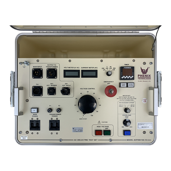
- Page 1 USER’S MANUAL AC DIELECTRIC TEST SET CASCADE TYPE Model Number 6CP200/100-10 Version 4.0 Phenix Technologies, Inc. 75 Speicher Drive Accident, Maryland 21520 Copyright © Phenix Technologies, Inc. Rev nab 5/28/2015 Rev Install Warning 2/13/2018 Rev 1387 Board Used 8/10/18 6CP200/100-10...
-
Page 2: Table Of Contents
OPERATIONAL VERIFICATION / GENERAL TEST CALIBRATION TROUBLESHOOTING MECHANICAL MAINTENANCE CHECKING OIL PURITY / SPECIFICATIONS TRANSPORTING / STORAGE OF EQUIPMENT CIRCUIT DIAGRAM SYMBOLS ELECTRICAL DIAGRAMS PARTS ORDERING INFORMATION RECOMMENDED SPARE PARTS PARTS LIST RETURNED MATERIAL CUSTOMER COMMENTS / SUGGESTIONS ATTACHMENTS PTC-13 TIMER MANUAL 6CP200/100-10... - Page 3 DANGER / WARNINGS WARNING !! DANGER Grounding of this unit is necessary for the safe operation of this equipment. Disconnect inputs before ungrounding this equipment 6CP200/100-10...
- Page 4 DO NOT operate damaged equipment. Remove power, and do not use the equipment until safe operation can be verified by service-trained personnel. Phenix Technologies, Inc. assumes no liability for unsafe or improper use of test equipment. 6CP200/100-10...
-
Page 5: Technical Specifications
High Voltage Divider: 40 lbs. (18 kg) Additional Equipment 22.5” (572mm) W x 29.25” (743mm) D x 50” (1270mm) H; Cart (2): 61 lbs. (27.7 kg) Cables: 20 lbs. (9.1 kg) 220V – 309 lbs. (140.2 Kg) Total Unit Weight: 6CP200/100-10... -
Page 6: Uncrating Procedure
1. Exercise care in removing shipping materials so as not to damage unit. 2. Perform visual inspection to determine if unit was damaged during shipment. If there are any signs of physical damage (such as dents, scratches, oil leaks), contact the Service Department at Phenix Technologies before proceeding. 6CP200/100-10... -
Page 7: Controls And Indicators
Match switch setting to output being used on HV transformer. 6. Overcurrent Trip. Use for presetting desired Overcurrent trip setting. Range approximately 10-110% of rated current. 7. Reset. Will light when Overcurrent Trip setting is exceeded. Push to reset. Lamp must be extinguished for HV ON. 6CP200/100-10... - Page 8 START/RESET again to reset timer to the original setting. Press HV OFF BYPASS to allow high voltage to remain on after the timer has expired. Test time can be set using the buttons on the face of the timer. 6CP200/100-10...
- Page 9 4. TX1 Connector. Signal/Metering cable connects from here to TX1 on control box. 5. Power Connector. Connect power cable from this point to multilamm style connectors on Top Module. 6. Lundeys. Provide sealed air-to-oil interface for connections. 6CP200/100-10...
- Page 10 7. Input Voltage Select. This jumper is used to select the input voltage in single cylinder and series operation. In parallel operation, the Top Module connection must match this jumper position. 8. High Voltage Electrode. (not shown) Provides connection point for HV output, and provides corona shielding for lundeys and cylinder edge. 6CP200/100-10...
- Page 11 Bottom Module. Cylinders should then be stacked and bolted together. 5. Clean High Voltage Modules using nothing stronger than ordinary household cleaner to remove all traces of any surface contamination. This cleaning should also include the High Voltage Electrodes. 6CP200/100-10...
-
Page 12: Initial Set-Up-Mechanical / Electrical
Connect the test specimen’s “low side” or ground to the ground stud on the Bottom Module using the supplied return lead. If the external interlock function is to be used, remove the jumper on the male cable end of the SX1 connector, and connect the external security circuit or footswitch at these points. 6CP200/100-10... - Page 13 The pipe should also be solidly connected at each end. Connect the input main power cable to the Main Input connection at the control box and then to the facility power source. 6CP200/100-10...
- Page 14 For guarded current measurement, connect the jumper between the GND and GRD terminals. Connect the test specimen return (low voltage side) to the RTN terminal. Do not connect the specimen return to ground. The test specimen must be totally isolated from ground. 6CP200/100-10...
- Page 15 INITIAL SET-UP--ELECTRICAL CURRENT METER GUARD CIRCUIT Figure 4-1 6CP200/100-10...
- Page 16 High Voltage will trip off and the Overcurrent Indicator Lamp will illuminate. With the front panel Overload Selector Switch set at 200 kV/50 mA, the trip point should be at approximately 5 mA. 14. Return Voltage Control to zero. Press HV Off Switch. Turn off Main Power Circuit breaker. 6CP200/100-10...
- Page 17 High Voltage load appropriate to the rated voltage and current of the test set. 17. Return Voltage Control to Zero. Press HV Off switch. Turn Off Main Power Circuit Breaker on Controls. END OF OPERATIONAL VERIFICATION TEST! 6CP200/100-10...
- Page 18 10. If during the test a failure should occur or if the Overcurrent Trip setting is exceeded, the High Voltage will automatically shut off. In order to regain High Voltage, press the Reset pushbutton and return the Voltage Control knob to Zero. 6CP200/100-10...
-
Page 19: Calibration
Repeat for 2 mA, 20 mA and 200 mA ranges adjusting R80, R82 and R84, respectively. (High Voltage load will need to change when changing range). NOTE: An optional method is to use current injection between RTN and GND (Guard Mode). Do not turn High Voltage on for this method! 6CP200/100-10... - Page 20 Once jumped, the offset should be adjusted until the output meter reads nearest to zero. This offset adjustment should be done before adjustments to the current ranges are made. Test point T37 may also be used to make this adjustment. 6CP200/100-10...
-
Page 21: Troubleshooting
Check main facility input power to the test set. Check all control and switch settings. Check indicating lamps. (Spare lamps are available through Phenix Technologies.) Check Fuse F1 and F2 Check operation of main power circuit breaker (CB1). Main Power lamp should be on. - Page 22 No input to voltage regulator section, possible problems with K9 on PCB 1387 or K3, regulator (T1), or with Transformer Power circuit breaker. Internal connection broken. High voltage winding of T301 or T302 short circuited. Refer also to 1 and 2 above. 6CP200/100-10...
-
Page 23: Mechanical Maintenance
It is recommended that the finish be wiped down for longer life and also for proper electrical operation of the unit. Also inspect all fabrication joints for oil leakage. If a leak is found, check hardware for tightness or consult Phenix Technologies Service Department. Control Box / Regulator Section At least once every year, the control assembly should be removed for inspection of the regulator assembly and other parts. -
Page 24: Checking Oil Purity / Specifications
SECTION 9: CHECKING OIL PURITY NOTE: Typical test data for the oil used by Phenix Technologies are provided at the end of this section. 1. The most reliable means of determining the purity of the oil in the field is to test the dielectric strength. Test sets for this purpose available on the market differ in design, particularly in the shape of the electrodes and the test container. - Page 25 Refractive Index ASTM 1218 Units Carbon N% ASTM D2140 Carbon A% ASTM D2140 Carbon P% ASTM D2140 Corrosive Sulfur ASTM D1275B Noncorrosive PCBs – Detection Unit 1 mg/kg ASTM D4059 mg/kg Not Detected Flash Point ASTM D92 0ºC 145 min 6CP200/100-10...
-
Page 26: Transporting / Storage Of Equipment
2. If the high voltage transformer is to be stored outdoors, it should be completely covered to prevent damage from environmental conditions. 3. In no case should the control box be stored outdoors 4. Prior to placing the equipment back into operation, all aspects of the maintenance schedule should be strictly adhered to. 6CP200/100-10... -
Page 27: Circuit Diagram Symbols
(Schliesser) Normally Closed Interrupteur Normalement Schrittshalter Maintained Switch Maintenu Ferme (Oeffner) Normally Closed Interrupteur Normalement Druckschalter Momentary Switch Ferme Momentanement (Oeffner) Normally Open Interrupteur Normalement Druckschalter Momentary Switch Ouvert Momentanement (Schliesser) Current Overload Dispositif De Sur UeberstromschutzEinheit Device Intensite 6CP200/100-10... -
Page 28: Electrical Diagrams
12-1 SECTION 12: ELECTRICAL DIAGRAMS Drawing Number Description 9602110 6CP200-10 System Diagram 7612110 Control and Regulator Schematic 7632110 HV Transformer Schematic 7662110 HV Divider Schematic MREF-012 200kV Switchgear Test Set Assembly Details 6CP200/100-10... -
Page 29: Parts Ordering Information
When your purchase order is received at our office, a representative of Phenix Technologies will contact you to confirm the current price of the part being ordered. If a part you order has been replaced with a new or improved part, an Applications Engineer will contact you concerning any change in part number. -
Page 30: Recommended Spare Parts
If the unit will be operated at an isolated site for an extended period or will be subjected to unusual stresses, a larger quantity of parts should be stocked as spares. In such a case, contact your Phenix Technologies' sales representative for a recommendation. - Page 31 15-1 SECTION 15: 6CP200/100-10 PARTS LIST Item Part Number Description Quantity CONTROL/REGULATOR CB1,CB2 1601332 2P CIRCUIT BREAKER CON1 1151178 RECEPTACLE CON1 1151183 HIGH CURRENT PINS, MALE CON2 1151179 RECEPTACLE CON2 1151185 HIGH CURRENT PINS, FEMALE D1-D5 1780028 DIODE 1151152 RECEPTACLE,...
- Page 32 X1-3, T1-2 1356312 MULTILAMM PLUG X1-3, T1-2 1356310 MULTILAMM SOCKET HIGH VOLTAGE DIVIDER C601-602 1090304 CAPACITOR 1151152 RECEPTACLE 1151175 CONTACT PINS, FEMALE GROUND 1351103 BINDING POST GREEN 1609990 NEON LAMP PCB 1282 31128204 PCB 1282 TB601 1156050 TERMINAL STRIP 6CP200/100-10...
-
Page 33: Returned Material
Serial Number Reason for Return Cause of Defect If Phenix Technologies, Inc. deems return of the part appropriate; it will then issue an "Authorization for Return." If return is not deemed advisable, other inspection arrangements will be made. NOTE: Material received at this plant without the proper authorization shall be held as "Customer's Property"... -
Page 34: Customer Comments / Suggestions
17-1 SECTION 17: CUSTOMER COMMENTS/SUGGESTIONS Phenix Technologies made significant efforts to ensure that the materials in this Operator’s Manual are correct. If there are concerns or comments as you have used this information, Phenix Technologies appreciates any feedback. Unit Serial Number:...
Need help?
Do you have a question about the 6CP200/100-10 and is the answer not in the manual?
Questions and answers