
Related Manuals for Phenix Technologies 400P


Summary of Contents for Phenix Technologies 400P
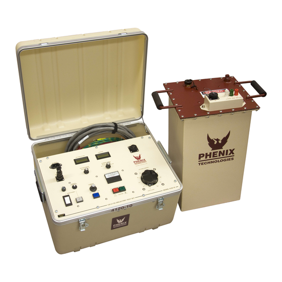
- Page 1 USER’S MANUAL DC DIELECTRIC TEST SET - 400P MODEL NUMBER 4120-10 Version 3.2 Phenix Technologies Inc. 75 Speicher Drive Accident, MD 21520 Copyright © Phenix Technologies, Inc. Rev 8/30/2018 ARFII Rev 8/9/2019 DCD 4120-10...
-
Page 2: Table Of Contents
TABLE OF CONTENTS DESCRIPTION SECTION NUMBER INTRODUCTION DANGER / GENERAL SAFETY PRECAUTIONS TECHNICAL SPECIFICATIONS CONTROLS AND INDICATORS ELECTRICAL SET-UP OPERATING INSTRUCTIONS RETURN-GROUND-GUARD CONNECTIONS CALIBRATION TROUBLESHOOTING STORAGE OF EQUIPMENT CIRCUIT DIAGRAM SYMBOLS RECOMMENDED SPARE PARTS AND PARTS LIST PARTS ORDERING INFORMATION RETURNED MATERIAL ELECTRICAL DIAGRAMS CUSTOMER COMMENTS / SUGGESTIONS... - Page 3 INTRODUCTION The DC Hipot line offered by Phenix Technologies is ruggedly built and suitable for field or lab use. Designed to test electrical switchgear, cables, motors, generators and protective equipment, DC testing is popular because the equipment is more compact and lighter in weight than comparable AC equipment Design and Safety Features ...
- Page 4 DANGER / WARNINGS DANGER Complete Grounding of this unit is necessary for the safe operation of this equipment. Disconnect inputs before ungrounding this equipment DCD 4120-10...
- Page 5 • DO NOT operate damaged equipment. Remove power, and do not use the equipment until safe operation can be verified by service-trained personnel. Phenix Technologies, Inc. assumes no liability for unsafe or improper use of test equipment. DCD 4120-10...
-
Page 6: Technical Specifications
SECTION 1: TECHNICAL SPECIFICATIONS Input 120 VAC 10 Amps or 220 VAC 5 Amps, 50/60 Hz, single phase (refer to Unit Data Tag) Output Rating (maximum) 120 kilovolts DC, 10 milliamperes Internal Discharge Capability: 12 kilojoules Duty Cycle Continuous – Capacitive Charging Type of Cooling: Natural convection Ripple: Less than 2 percent, at 120kV, (>... -
Page 7: Controls And Indicators
SECTION 2: CONTROLS AND INDICATORS Control Unit (Refer to Figure 2-1) AC Power Input. Connect to a suitable grounded receptacle. See specifications tag on unit for voltage and current requirements. Voltmeter. Displays output voltage of test set. Currentmeter. Displays current out of high voltage lead or into RTN terminal depending upon mode of measurement. - Page 8 CONTROLS AND INDICATORS Control Unit (Cont’d) Reset. Reset lamp illuminates to show that current trip circuit has tripped. High voltage circuits are deactivated. Momentary Reset switch must be pressed to extinguish Reset lamp to allow high voltage to be reapplied after returning Voltage Control to zero. VOLTMETER RANGE SELECTOR.
- Page 9 CONTROLS AND INDICATORS FIGURE 2-1 DCD 4120-10...
- Page 10 CONTROLS AND INDICATORS CONTROLS (Cont’d) High Voltage Unit (Refer to Figure 2-2) J5. Interconnect cable from controls connects here. Guard Terminal (GRD). Connect to Ground (GND) terminal (#3) for guard mode operation. Connect currents that need to bypass the currentmeter to this point. Low potential side of specimen must be isolated from ground to use this mode.
- Page 11 CONTROLS AND INDICATORS FIGURE 2-2 DANGER HIGH VOLTAGE DCD 4120-10...
-
Page 12: Electrical Set-Up
SECTION 3: ELECTRICAL SET-UP 1. Locate the desired location for the test set. Prepare the main power input cable for plugging into the proper facility power (i.e., 120 volts AC or 220 volts AC). Leave plug unconnected at this time. High Voltage Connection WARNING Main Power switch on front panel must be in the OFF (O) position before proceeding. -
Page 13: Operating Instructions
SECTION 4: OPERATING INSTRUCTIONS WARNING: This equipment should only be operated by personnel familiar with high voltage testing and safety procedures. Improper operation may result in injury or death and can cause damage to the unit or test object. Ensure proper electrical set-up has been performed. Check that the Voltage Control dial is set to "0"... - Page 14 OPERATING INSTRUCTIONS Calculating Meg-Ohms The Impedance of a test object can be determined by the formula: V/I=R where voltage in Volts divided by current in Amps equals Resistance in Ohms. Resistance divided by 1,000,000 then equals Meg-Ohms: R/1,000,000=Meg-Ohms When voltages are in Kilovolts and currents are in Milliamps, a more direct method is to directly divide Kilovolts by Milliamps to obtain the result directly in Meg-Ohms.
-
Page 15: Return-Ground-Guard Connections
SECTION 5: RETURN-GROUND-GUARD CONNECTIONS The unit contains a currentmeter feature useful in measurement of different current sources. 1. Return Mode (RTN) (Grounded Return Mode) This is the standard measurement configuration. The Ground jumper is installed between the Ground (GND) post and the Return (RTN) post. The low potential side of the test specimen is connected to Return. - Page 16 RETURN-GROUND-GUARD CONNECTIONS DANGER HIGH VOLTAGE DANGER HIGH VOLTAGE ...
- Page 17 RETURN-GROUND-GUARD CONNECTIONS DCD 4120-10...
-
Page 18: Calibration
SECTION 6: CALIBRATION CAUTION Calibration should only be done by persons familiar with High Voltage testing and safety procedures. All calibrations have been done at the factory. Periodic calibration of the output voltmeter and output currentmeter should be done annually. NOTE: Refer to Electrical Diagram Section for schematics pertaining to the model number of your test set. - Page 19 CALIBRATION Overcurrent This calibration should not need adjustment (factory adjusted). If the Overcurrent Circuit is out of calibration, perform the following steps. With unit off, short the output terminal to ground through an appropriate currentmeter. (A High Voltage Load will give better resolution and make calibration easier and more accurate. Minimum recommended resistance: 100K ohm, 100 watt.).
-
Page 20: Troubleshooting
If the controls do not operate properly after having been used according to the instructions, the following hints may help. • Check main facility input power to the test set. • Check indicating lamps. (Spare lamps are available through Phenix Technologies.) • Check fuse-F1. • Check all external plug connections on the test set. -
Page 21: Storage Of Equipment
SECTION 8: STORAGE OF EQUIPMENT If the equipment will be stored for a prolonged period, the following precautions are recommended. 1. The equipment should be covered and kept in a warm, dry environment (95% maximum humidity, 5 to 40 Celsius). 2. -
Page 22: Circuit Diagram Symbols
SECTION 9: CIRCUIT DIAGRAM SYMBOLS CIRCUIT DIAGRAM SYMBOLS SYMBOLES POUR SCHEMA DE CIRCUIT SYMBOLE ZU SCHEMA SYMBOL DESCRIPTION DESCRIPTION BEMENKUNG Amplifier Unite d'amplificateur Verstarker ARSR Surge Arrestor Parafoudre Ueberspannungsableiter Capacitor Condensateur Kondensator BSHG Bushing Tranversee Durchfuehoung Electrolytic Capacitor Condensateur electrol Eleckrolytik kondensator Fuse Fusible... - Page 23 If the unit will be operated at an isolated site for an extended period or will be subjected to unusual stresses, a larger quantity of parts should be stocked as spares. In such cases, contact Phenix Technologies for a recommendation.
- Page 24 10-2 4120-10 PARTS LIST ITEM DESCRIPTION PART NO. CONTROLS C1, 4 47uF 20V Capacitor 1096510 C2, 3 1 uF 50V Capacitor 1094051 C5, 6 .033 uF 630v Capacitor 1093300 CABLE-INTERCONNECT 25 FT. INTERCONNECT CABLE ASSY. 30160002 CASE HD POLY CASE 2100507 CIRCUIT BREAKER, 10 AMP, 2-POLE 1601314...
- Page 25 10-3 4120-10 PARTS LIST CONTROLS (CONT’D) VARIABLE TRANSFORMER 1890120 T2 (220V ONLY) STEP DOWN AUTO TRANSFORMER 1894433 Z1-4 1.5KE18A TRANSORB 1780065 1.5KE18C TRANSORB 1780069 ITEM DESCRIPTION PART NO. HV UNIT HV JACK PROTECTIVE CAP 1150968 1Uf, 50v 1092098 BINDING POST, GREEN 1351103 BINDING POST, RED 1351104...
-
Page 26: Parts Ordering Information
When your purchase order is received at our office, a representative of Phenix Technologies will contact you to confirm the current price of the part being ordered. If a part you order has been replaced with a new or improved part, an applications engineer will contact you concerning any change in part number. -
Page 27: Returned Material
Serial Number Reason for Return Cause of Defect If Phenix Technologies, Inc. deems return of the part appropriate, it will then issue an "Authorization for Return." If return is not deemed advisable, other inspection arrangements will be made. NOTE: Material received at this plant without the proper authorization shall be held as "Customer's Property"... -
Page 28: Electrical Diagrams
13-1 SECTION 13: ELECTRICAL DIAGRAMS Drawing Number Description 1. 9400124 Model Number 4120-10 Control 2. 8430124 HV DC Tank Assembly—4120-10 DCD 4120-10... -
Page 29: Customer Comments / Suggestions
14-1 SECTION 14: CUSTOMER COMMENTS / SUGGESTIONS Phenix Technologies made significant efforts to ensure that the materials in this Operator’s Manual are correct. If there are concerns or comments as you have used this information, Phenix Technologies appreciates any feedback.
Need help?
Do you have a question about the 400P and is the answer not in the manual?
Questions and answers