Table of Contents
Advertisement
Quick Links
Advertisement
Table of Contents

Related Manuals for Phenix Technologies PM10A


Summary of Contents for Phenix Technologies PM10A
- Page 1 PM10A 10 kV Insulation tester User’s Manual Phenix Technologies, Inc 75 Speicher Drive Accident, Maryland 21520 Tel: 1 (301) 746-8118 Fax: 1 (301) 895-5570 E-mail: info@phenixtech.com (GU-1547RB) © 2016 Phenix Technologies, Inc. All rights reserved. Rev 8/6/2016 nab PM10A...
- Page 2 Equipment complies with current EU Directives. The rubbish bin with a line through it means that in the European Union, the product must undergo selective disposal for the recycling of electric and electronic material, in compliance with Directive WEEE 2002/96/EC. PM10A...
-
Page 3: Table Of Contents
2. Panel control functions ..................5 2.1. Keyboard ....................6 2.2. Display ....................... 7 3. Charging battery ....................8 4. Connecting the PM10A ..................9 5. Use of “Guard” (G) terminal ................10 6. Setting tests ....................11 6.1. Test voltage definition ................11 6.2. -
Page 4: Description
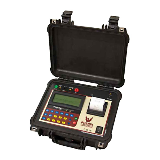
1. Description The digital insulation tester model PM10A is an advanced insulation analyzer, and it is one of the more complete and sophisticated on the international market. It uses an efficient, well tested technology that provides safe, reliable, and accurate measurements of insulation resistances up to 10 TΩ, with 4 preselected test voltages: 500 V - 1 kV - 5 kV. - 10 kV. -
Page 5: Panel Control Functions
2. Panel Control Functions 1. Voltage Output Terminal (-V) 2. Zero Reference Terminal (+R) 3. Guard (G) Terminal 4. Display Screen 5. USB Communication Port 6. High Voltage LED 7. Keyboard 8. On / Off Key 9. Power Supply Input 10. Printer PM10A... -
Page 6: Keyboard
100 V steps activated step tests voltages Activated, enables programming of 500 V 500 V steps activated step tests voltages Selection of 500 V test voltage Indicates 500 V selected Selection of 1 kV test voltage Indicates 1 kV selected PM10A... -
Page 7: Display
Stop - End of test 2.2 Display Measurement results in the corresponding measuring unit, elapsed time since the measurement started, selected test voltage, analog indication by means of a bar graph, and several messages to the operator are displayed on alphanumeric LCD. PM10A... -
Page 8: Charging Battery
Charging procedure: Check if the PM10A is turned-off and connect it to the mains (AC adapter). The charging indicator ( ) will turn on red and will remain that way until the battery is fully charged. -
Page 9: Connecting The Pm10A
ATTENTION: For safe operation, follow the procedures detailed below with the device Powered-Off. Check if there is no difference of potential voltages between the points where the PM10A shall be connected to. Also, check the same between those points and the ground. -
Page 10: Use Of "Guard" (G) Terminal
GUARD or R terminals must be grounded, but not both of them simultaneously. Technical Note 32, reproduced at the end of the manual, explains the usage of GUARD terminal in order to eliminate the unwanted resistance effect over the result of measurements. PM10A... -
Page 11: Setting Tests
NOTE: Test voltage is the only one parameter that may be modified during tests. 6.2 Selection of the operation mode The PM10A insulation tester has four operation modes: Normal, with TIMER, SVT, and Pass / Fail. The first three key; the “Pass/ Fail” test mode is activated pressing modes are selected using the key. -
Page 12: Svt Mode (Step Voltage Tests)
6.2.2 SVT Mode (step voltage tests) The use of key allows the PM10A setting for the performance of a step voltage test; when this mode is selected, the display shows the SVT abbreviation. Under this operation mode, the user does not define a specific voltage test, but a maximum voltage value. The device will start the test applying a 500 V voltage and increase this value in 500 V steps each minute until reaching the programmed voltage. -
Page 13: Timer Mode
Press keys. Possible values are 10 MΩ, 100 MΩ, 1 GΩor 10 GΩ. During a Pass / Fail test, the PM10A will indicate when the insulation resistance is lower than the programmed limit, both with an intermittent beep and the key led flashing. -
Page 14: How To Perform Tests
In order to end the test, press the key. At that moment, the last measured values will remain frozen in the PM10A display. By pressing the key again, the equipment will return to the voltmeter function. -
Page 15: Measurement Of The Dielectric Absorption Index (Dai)
The polarization index is the quotient between the values of the insulation resistance measured both in 10 minutes and 1 minute. This index is useful to detect the damage of the insulation resistance by the excessive presence of dust, dirt and greases or through the action of chemical and physical agents. t e s PM10A... -
Page 16: Other Functions
2,500V 30nF up to 2µF 5,000V 30nF up to 1µF 10,000V 30nF up to 680µF Precision: ± 10% of the measured value ± 3 digits Note: “0” will be exhibited on the display when measuring values lower than 50nF PM10A... -
Page 17: Hold
If the battery charge is under 20% of the total, the message Battery Low will automatically appear on the display. 8.9. Auto power-off The PM10A auto-turns off after 10 minutes of inactivity, or after 95 minutes of measuring without checking the battery status. PM10A... -
Page 18: Software
It synchronizes the date and time of the equipment internal clock with the computer date and clock, to transfer the stored date, to clear the memory, and to generate test graphics and protocols, etc. The installation and operation instructions are included in the software. PM10A... -
Page 19: Printer
The panel, terminals, and connectors of the equipment must stay dry and clean. Cleaning should be made using a soft detergent or isopropyl alcohol (be sure that the products to be used for cleaning do not affect plastic goods). PM10A... -
Page 20: Technical Specifications
: Prints elapsed time, actual voltage applied to Printer the element under test, and measured resistance : USB PC Interface : Indicates elapsed time from the beginning of Built-in chronometer the measurement mm:ss format, up to 90:00 : IP54 (with closed lid) Environmental protection index PM10A... - Page 21 : L 16” (406 mm) x W 13” (330 mm) x H 7” (174 Dimensions : • 3 measurement cables Supplied accessories • AC Adapter • USB cable • Carrying bag • Operation manual • License for MegaLogg2 software Subject to technical change without notice. PM10A...
-
Page 22: Application Note 32
Rx appears to be in parallel with (R1 + R2). The situation is changed if connecting the transformer housing to GUARD terminal. Then the circuit will be: PM10A... - Page 23 100 MΩ, any value of Rx will be measured with an insignificant error. For example: Let us consider Rx = 3000MΩ and R1 = R2 = 100 MΩ, the reading without using the GUARD terminal would be 187.5MΩ, which is quite wrong. On the other hand, if the GUARD terminal is properly used, we would have 3000MΩ. PM10A...
-
Page 24: Customer Comments / Suggestions
SECTION 14. CUSTOMER COMMENTS / SUGGESTIONS Phenix Technologies made significant efforts to ensure that the materials in this Operator’s Manual are correct. If there are concerns or comments as you have used this information, Phenix Technologies appreciates any feedback. Unit Serial Number:...
Need help?
Do you have a question about the PM10A and is the answer not in the manual?
Questions and answers