
Related Manuals for Phenix Technologies HC-20C


Summary of Contents for Phenix Technologies HC-20C
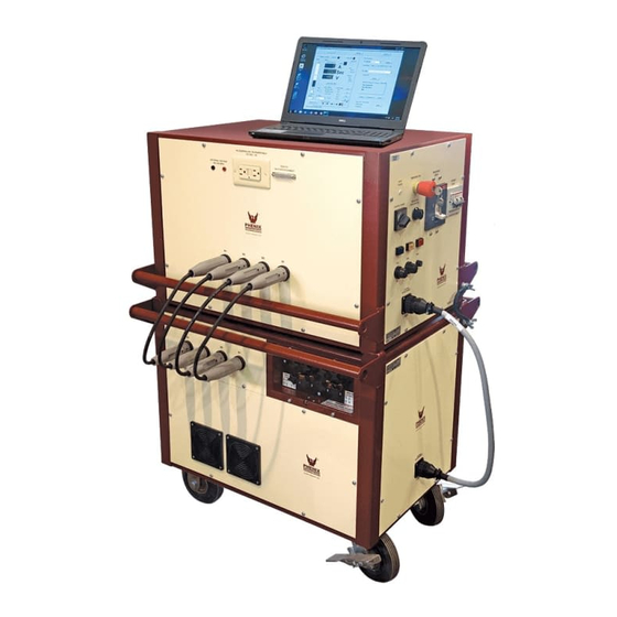
- Page 1 TEST AC CIRCUIT BREAKER OPERATOR’S MANUAL Version 2.0 MODEL HC-20C Phenix Technologies, Inc 75 Speicher Drive Accident, MD 21520 Copyright © Phenix Technologies, Inc. Rev 6/5/2017 nab HC-20C...
-
Page 2: Table Of Contents
INSTALLATION INSTRUCTIONS POWER ON/OFF PROCEDURE POWER SECTION DESCRIPTION TESTING PROCEDURE TROUBLESHOOTING SERVICE AND MAINTENANCE CALIBRATION OF CIRCUIT BREAKER TEST SETS WinHC PC SOFTWARE RETURNED MATERIAL PARTS ORDERING INFORMATION RECOMMENDED SPARE PARTS PARTS LIST ELECTRICAL SCHEMATICS CUSTOMER COMMENTS / SUGGESTIONS HC-20C... - Page 3 WARNING !! Complete Grounding of this unit is necessary for the safe operation of this equipment. Disconnect inputs before un- grounding this equipment HC-20C...
- Page 4 DO NOT operate damaged equipment. Remove power, and do not use the equipment until safe operation can be verified by service-trained personnel. Phenix Technologies, Inc. assumes no liability for unsafe or improper use of test equipment. HC-20C...
-
Page 5: Specifications
DUTY CYCLE Continuous 2 Minutes OFF 10 Minutes OFF 30 Minutes OFF HC-12C 12,000 A 2,500 A 1,700 A 1,200 A HC-20C 20,000 A 4,500 A 3,000 A 2,000 A HC-40C 40,000 A 9,000 A 6,000 A 4,000 A HC-75C... - Page 6 Ranges: 0 - 999.999 Seconds 0 - 99,999.990 Cycles Test durations of less than 10 cycles Timer Accuracy: ± 0.004 Seconds ± 0.250 Cycles Test durations of greater then 10 cycles Timer Accuracy: ± 0.010 Seconds ± 0.600 Cycles HC-20C...
-
Page 7: Introduction
SECTION 2: INTRODUCTION Phenix Technologies' High Current Test Sets represent a new era of electrical testing technology. This design is based on time-proven concepts and the power offered by an embedded 32-bit microcomputer. High reliability SCRs have been combined with a phase angle firing system to deliver precisely repeatable current pulses with minimal distortion. -
Page 8: Safety
SECTION 3: SAFETY Several safeguards have been built into the Phenix Technologies high current test sets; however, these safeguards are only effective if safe work practices are also used. The test set and these procedures have been designed for use by knowledgeable electrical workers who have been properly trained in its use. -
Page 9: Installation Instructions
Position the test set in the desired position. For 2-cabinet units, place the regulator cabinet on top of the transformer cabinet. The following procedure is only required for 2-cabinet units (HC-12C and HC-20C): Connect the interconnect ground cable from the regulator cabinet to the transformer cabinet. - Page 10 INSTALLATION INSTRUCTIONS HC-12C, HC-20C, and HC40C INPUT POWER JUMPER CONFIGURATIONS: REGULATOR (TOP) CABINET 220-240V CONNECTION TRANSFORMER (BTM) CABINET 1 2 3 4 220-240V 440-480V 220-240V CONNECTION CONNECTION CONNECTION 380-480V 220-240V CONNECTION CONNECTION DANGER 380-416V CONNECTION INPUT VOLTAGE SELECT REMOVE POWER FROM UNIT...
-
Page 11: Power On/Off Procedure
Switch CB202 (vernier circuit breaker) OFF. Switch the control power OFF (SW201). De-energize the facility power distribution breaker. Disconnect the test set as required. WARNING: Connecting or disconnecting the controller with power applied may damage test set and/or controller. HC-20C... -
Page 12: Power Section Description
An SCR Trigger board, PCB201, turns the high current output ON when signaled by the HC Controller. The trigger board receives its command from the HC Controller via an I/O interface PC board, PCB202. The HC Controller precisely controls the phase angle and duration of the output waveform. HC-20C... - Page 13 Normally Open test modes by the test set. If the continuity connections cannot be used (i.e. a single-phase breaker), the set must be operated in the Current Latch mode. CAUTION: DO NOT CONNECT CONTINUITY TERMINALS TO ENERGIZED SOURCE. DAMAGE TO CONTROLLER WILL OCCUR! HC-20C...
- Page 14 Connect between the Chassis Ground Terminal and the facility Ground Cable ground. Output Stabs Connection to the circuit breaker under test. Continuity Binding Post For use in contact mode, i.e. Normally Closed or Normally Open. Regulator Speed Control Controls the vernier speed. HC-20C...
-
Page 15: Testing Procedure
Twisting the cables will also help to reduce noise on the current measurement. SAVING RESULTS After a test is performed and while test results are still displayed, click the Save Result button. HC-20C... - Page 16 This mode is used to maintain a preset current value for a long period of time. Click Settings in Test Parameters to access the test parameters. See the specific procedures for the different Test Modes on the next few pages. HC-20C...
- Page 17 Click Settings in Test Parameters. Enter the number of cycles that the output will be energized. This should be long enough to get a good reading, but short enough to avoid overheating. Phenix Technologies recommends a value of 7 cycles.
- Page 18 This should be long enough to get a good reading and at least twice the expected instantaneous trip time, but short enough to avoid overheating. Phenix Technologies recommends a value of 7 cycles. Be sure to click OK to record the setting.
- Page 19 Click the START button to energize the output. Click the STOP button to stop the test at any time. The test set will hold the current until the breaker trips or the operator interrupts the test. Optional – click Save Results. HC-20C...
- Page 20 The test set will automatically increase the current up to the HOLD AMPS setting and remain ON until either the operator clicks STOP, the circuit breaker trips, or the MAX DURATION or MAX CYCLES is reached. Click the STOP button to stop the test at any time. HC-20C...
-
Page 21: Troubleshooting
Check to see that main circuit breaker is on. Verify that the breaker is reset and not in the trip position. Verify continuity of the breaker contacts. Check LED indicator on SCR trigger board. It should light when initiated. Check voltage out of SCR's when initiated. HC-20C... -
Page 22: Service And Maintenance
Remove the front cover on the main circuit breaker and clean the main contacts. Replace the contacts if they are beyond repair. Inspect the variable transformer brushes for wear. Replace if they appear worn. Perform basic operational tests to determine proper operation. HC-20C... -
Page 23: Calibration Of Circuit Breaker Test Sets
This is a self calibrating function, when selected the variac will automatically run from limit to limit to adjust the systems 0% & 100% position sensors. Calibrate Current Meter: When selected you will get the following screen. Enter password 8118. After password is entered you will see the following screen. HC-20C... - Page 24 NOTE: For the 100 kA range your standard will most likely be a much smaller value than your range. In this case you should calibrate near 100% of your standard’s value. The standard should be at least 20% of range. HC-20C...
- Page 25 For this calibration you will inject voltages into the banana jacks over the output panel. (NOT CONTINUITY BINDING POSTS) Raise the voltage source to approximately 80% of range. Enter the value from your standard in the Actual Voltage field and press update. The Cal Factor will automatically update. Repeat for other ranges. HC-20C...
- Page 26 It is recommended that documentation of the cal factors be maintained, in the event that the cal factors become corrupt or if inadvertently changed and need to be restored. This can be done by going to the Hardware Settings screen. HC-20C...
-
Page 27: Winhc Pc Software
SECTION 11: WinHC PC Software About WinHC Welcome to WinHC, circuit breaker test system software developed by Phenix Technologies to control the Phenix Technologies high current test sets. WinHC provides advanced database and report generation capabilities, enabling you to save your circuit breaker test results in a database for future recall and report generation. - Page 28 Vernier Control: The position of the vernier determines the level of the output voltage and current of the WinHC. Click the up/down arrows to change the position of the vernier, or enter a vernier position and click Go... HC-20C...
- Page 29 You MUST NOT enter a desired test current that is at or above the level where the breaker under test will trip. If the breaker trips during initialization, then the process will be aborted. HC-20C...
- Page 30 Use the Output Control screen to perform the circuit breaker test. When the test is complete, click Save Result to save the test results. Click Waveform... to view the waveform of the output current. HC-20C...
- Page 31 NOTE: The search will be performed on the field selected by Sort By…. 4. Click Test Report… to generate a report. You will be given the option of pre-viewing the report on screen or sending it directly to the printer. HC-20C...
- Page 32 WinHC data to a network server. You are responsible for moving the data files, if you change this setting without moving the files, WinHC will create empty data files in the new location. HC-20C...
- Page 33 The labels options screen contains the field labels for the optional circuit breaker nameplate fields. You may change any of these to suit your particular needs. These labels appear on the circuit breaker nameplate screen, under Additional Info…, and on test reports. Lists The Lists Options HC-20C...
- Page 34 Tests The Tests Options Circuit breaker Test Titles: You may customize the test titles to match your individual testing procedures. Test Titles appear on the test screen and print on test reports. HC-20C...
- Page 35 The backup data screen allows you to easily select a drive/directory as a destination for your data backup. Access this screen by selecting Tools and then Backup Data…. Select the drive/directory and Click Backup Data to begin the backup. HC-20C...
- Page 36 The restore data screen allows you to easily select a drive/directory as a source for your data recovery. Access this form by selecting Tools and then Restore Data…. Select the drive/directory and Click Restore Data to begin the data recovery. HC-20C...
-
Page 37: Returned Material
Serial Number Reason for Return Cause of Defect If Phenix Technologies, Inc. deems return of the part appropriate, it will then issue an "Authorization for Return." If return is not deemed advisable, other inspection arrangements will be made. NOTE: Material received at this plant without the proper authorization shall be held as "Customer's Property"... -
Page 38: Parts Ordering Information
When your purchase order is received at our office, a representative of Phenix Technologies will contact you to confirm the current price of the part being ordered. If a part you order has been replaced with a new or improved part, an Applications Engineer will contact you concerning any change in part number. -
Page 39: Recommended Spare Parts
14-1 SECTION 14: RECOMMENDED SPARE PARTS HC-20C In order to maintain your set in full operating condition with a minimum of down time, the following spare parts should be kept on hand to avoid unnecessary phone calls, expensive modes of shipment, delays in repairs, etc. -
Page 40: Parts List
15-1 SECTION 15: HC-20C PARTS LIST Phenix Part # Item Description CONTROLLER RIGHT ANGLE USB CABLE, 2’ 1001402 CABLE 101-104 1079908 CABLE 105-107 RIBBON CABLE 1152145 CABLE 37 PIN TO RIBBON 1152160 CABLE 40 PIN CONN 1152248 3CKT 1152590 CON1... - Page 41 15-2 HC-20C PARTS LIST Phenix Part Item Description REGULATOR AND HIGH CURRENT SECTION (continued) 1601052 CB201 Circuit Breaker, 2 Pole, 150A w / 24VDC UVR 1601504 CB202 Circuit Breaker, 2 Pole, 32A w / Aux. Contacts, 1601506 CB202 Aux. Auxiliary Contacts, #S500-H11...
- Page 42 HC-20C PARTS LIST Phenix Part # Item Description REGULATOR AND HIGH CURRENT SECTION (continued) 31115600 PCB201 Trigger Board, PCB1156 31115520 PCB202 Input/Output Board, PCB1155B 31125210 PCB203 RMS-to-DC Converter, PCB1252 1590293 PS201 Power Supply, 24VDC 1590168 PS201 Power Supply, 24VDC 1714010...
-
Page 43: Electrical Schematics
PCB 1389, HC Interface BD 31139100 PCB1391, HC Interconnect BD HC Regulator / Transformer Cabinet(s) Drawing Number Description 9304553 HC-20C Electrical Schematic 31115520 PCB 1155B, HC I/O Interface Schematic 31115600 PCB 1156, SCR Trigger Board 31125210 PCB 1252A, RMS-to-DC Converter... -
Page 44: Customer Comments / Suggestions
17-1 SECTION 17: CUSTOMER COMMENTS / SUGGESTIONS Phenix Technologies made significant efforts to ensure that the materials in this Operator’s Manual are correct. If there are concerns or comments as you have used this information, Phenix Technologies appreciates any feedback.
Need help?
Do you have a question about the HC-20C and is the answer not in the manual?
Questions and answers