Table of Contents

Related Manuals for Phenix Technologies 6CP50/10-3


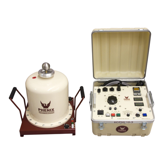
Summary of Contents for Phenix Technologies 6CP50/10-3
- Page 1 USER’S MANUAL AC DIELECTRIC TEST SET 600P Series Model Number 6CP50/10-3 Version 2.4 Phenix Technologies, Inc. 75 Speicher Drive Accident, Maryland 21520 Copyright © Phenix Technologies, Inc JSH/slu JAN 2013 Rev 5/17/2017 JSH 6CP50/10-3...
-
Page 2: Table Of Contents
OPERATING INSTRUCTIONS CALIBRATION TROUBLESHOOTING MECHANICAL MAINTENANCE CHECKING OIL PURITY / SPECIFICATIONS TRANSPORTING / STORAGE OF EQUIPMENT CIRCUIT DIAGRAM SYMBOLS ELECTRICAL DIAGRAMS PARTS ORDERING INFORMATION RECOMMENDED SPARE PARTS PARTS LIST RETURNED MATERIAL CUSTOMER COMMENTS / SUGGESTIONS ATTACHMENTS PTC-13 TIMER MANUAL 6CP50/10-3... - Page 3 DO NOT operate damaged equipment. Remove power, and do not use the equipment until safe operation can be verified by service-trained personnel. Phenix Technologies, Inc. assumes no liability for unsafe or improper use of test equipment. 6CP50/10-3...
-
Page 4: Technical Specifications
16.5" (419 mm) W x 15.25" (388 mm) D x 11.25" (286 mm) H Weight: 29 pounds (13 kg) Add 3 pounds (1.4kg) for 220V 14” (356 mm) W x 14” (356 mm) D x 16.88” (429 mm) H HV Transformer: Weight: 80 pounds (36 kg) 6CP50/10-3... -
Page 5: Controls And Indicators
3. High Voltage On. Momentary switch activates power to high voltage circuits when pre-required conditions are met. Ready lamp (4) must be illuminated before High Voltage On switch will operate. See requirements for Ready lamp under step 4. High Voltage On lamp illuminates to indicate high voltage circuits are energized. 6CP50/10-3... - Page 6 This is the metering and return connection. Do not attempt to operate high voltage unit without this cable connected at both ends. 12. TX1. Provided power interconnect cable connects here and to the same designation connector on high voltage unit. 13. Line Cord. Supplies 220V input power to unit. 6CP50/10-3...
- Page 7 16. Start/Reset. Press to start the timer after test voltage has been reached. Press again to reset the timer to the original setting. 17. HV Off Bypass. Press to allow high voltage to remain on after timer has expired. Indicator lights when depressed. 18. Timer. Select desired test time using buttons on face of timer. See Attachment 6CP50/10-3...
-
Page 8: Electrical Set-Up
3. Check that control circuit breaker is turned off and connect input main power cable to a suitable grounded receptacle Brief connection instructions and a diagram are on following pages. 6CP50/10-3... - Page 9 Connect high potential side of test specimen to either the 10kV (side) or 50kV (top) high voltage output. Connect main power cord to appropriate receptacle. (Further instructions on test connections may be found in ANSI C37.60) 6CP50/10-3...
- Page 10 (NOTE: Ensure the Ground (“GND”) post is grounded.) CAUTION If the test specimen is not fully isolated from ground, the current meter will either not work, or not display accurate current readings, and this mode should not be used. 6CP50/10-3...
- Page 11 ELECTRICAL SETUP Figure 4-1 6CP50/10-3...
-
Page 12: Operating Instructions
To regain high voltage, the Raise Voltage dial must be returned to zero and the Overcurrent Reset button must be depressed (lamp will extinguish). After all testing is complete, turn off the front panel circuit breaker. Remove the input power cable from the facility power input. 6CP50/10-3... -
Page 13: Calibration
Raise the output to approximately 80% of the rated output voltage. Adjust the reading on the panel meter (M2) by means of potentiometer R2 to a corresponding reading. Check linearity at several points from 20% to 100% of rated tap voltage. 6CP50/10-3... - Page 14 Repeat steps a through g as necessary until both settings are calibrated. 4. Range Overcurrent. R235 sets an overcurrent for the ranges and should be set to trip at approximately 110% of full range current on medium range setting with current trip potentiometer set at “11.” 6CP50/10-3...
-
Page 15: Troubleshooting
Check main facility input power to the test set. Check indicating lamps. (Spare lamps are available through Phenix Technologies.) Check operation of the circuit breaker (CB1). Control Power lamp should be on when the circuit breaker is ... - Page 16 6. No output voltage from high voltage section? - Defective metering circuit. - No input to voltage regulator section, possible problems with K3 contacts, variable transformer, or with CB1. - Shorted high voltage output. - Defective high voltage output transformer. - Defective TX1 cable or connector. 6CP50/10-3...
-
Page 17: Mechanical Maintenance
At time intervals, ranging from six months to one year, the oil purity (see Section 9) should be checked in the high voltage transformer to verify its reliability. If the transformer is subject to adverse weather conditions or an oil leak develops, the oil purity should be checked regularly. 6CP50/10-3... -
Page 18: Checking Oil Purity / Specifications
SECTION 9: CHECKING OIL PURITY NOTE: Typical test data for the oil used by Phenix Technologies are provided at the end of this section. 1. The most reliable means of determining the purity of the oil in the field is to test the dielectric strength. Test sets for this purpose available on the market differ in design, particularly in the shape of the electrodes and the test container. - Page 19 Refractive Index ASTM 1218 Units Carbon N% ASTM D2140 Carbon A% ASTM D2140 Carbon P% ASTM D2140 Corrosive Sulfur ASTM D1275B Noncorrosive PCBs – Detection Unit 1 mg/kg ASTM D4059 mg/kg Not Detected Flash Point ASTM D92 0ºC 145 min 6CP50/10-3...
-
Page 20: Transporting / Storage Of Equipment
3. In no case should the control box be stored outdoors (unless previously specified in the original purchase agreement). 4. Prior to placing the equipment back into operation, all aspects of the maintenance schedule should be strictly adhered to. 6CP50/10-3... -
Page 21: Circuit Diagram Symbols
(Schliesser) Normally Closed Interrupteur Normalement Schrittshalter Maintained Switch Maintenu Ferme (Oeffner) Normally Closed Interrupteur Normalement Druckschalter Momentary Switch Ferme Momentanement (Oeffner) Normally Open Interrupteur Normalement Druckschalter Momentary Switch Ouvert Momentanement (Schliesser) Current Overload Dispositif De Sur UeberstromschutzEinheit Device Intensite 6CP50/10-3... -
Page 22: Electrical Diagrams
12-1 SECTION 12: ELECTRICAL DIAGRAMS Drawing Number Description 9602004 6CP50/10-3 ELECTRICAL SCHEMATIC (120V) 9602005 6CP50/10-3 ELECTRICAL SCHEMATIC (220V) 6CP50/10-3... -
Page 23: Parts Ordering Information
When your purchase order is received at our office, a representative of Phenix Technologies will contact you to confirm the current price of the part being ordered. If a part you order has been replaced with a new or improved part, an Applications Engineer will contact you concerning any change in part number. -
Page 24: Recommended Spare Parts
If the unit will be operated at an isolated site for an extended period or will be subjected to unusual stresses, a larger quantity of parts should be stocked as spares. In such a case, contact your Phenix Technologies' sales representative for a recommendation. - Page 25 15-1 SECTION 15: 6CP50/10-3 PARTS LIST ITEM DESCRIPTION PART NO. CONTROLS PCB1257 PCB1257 METER/OVERLOAD BD (6CP50/10-3) 31125722 CB1 (220V) CIRCUIT BREAKER, 10 AMP, 2-POLE 1601312 CB1 (120V) CIRCUIT BREAKER, 20 AMP, 1-POLE 1601320 CB1 (120V) CIRCUIT BREAKER HOLE COVER 1601395...
-
Page 26: Parts List
1151196 INTERCONNECT CABLES POWER INTERCONNECT CABLE – 6 FT 7 IN. TX1 CABLE 1077140 TX2 CABLE SIGNAL INTERCONNECT CABLE- 10 FT 30060008 GND CABLE 10 FT. GROUND CABLE ASSY. 30080008 RTN CABLE 10 FT. SPECIMEN RETURN CABLE ASSY. 30080009 6CP50/10-3... -
Page 27: Returned Material
Reason for Return Cause of Defect If Phenix Technologies, Inc. deems return of the part appropriate; it will then issue an "Authorization for Return." If return is not deemed advisable, other inspection arrangements will be made. NOTE: Material received at this plant without the proper authorization shall be held as "Customer's Property" with no service until such time as the proper steps have been taken. -
Page 28: Customer Comments / Suggestions
17-1 SECTION 17: CUSTOMER COMMENTS/SUGGESTIONS Phenix Technologies made significant efforts to ensure that the materials in this Operator’s Manual are correct. If there are concerns or comments as you have used this information, Phenix Technologies appreciates any feedback. Unit Serial Number:...
Need help?
Do you have a question about the 6CP50/10-3 and is the answer not in the manual?
Questions and answers