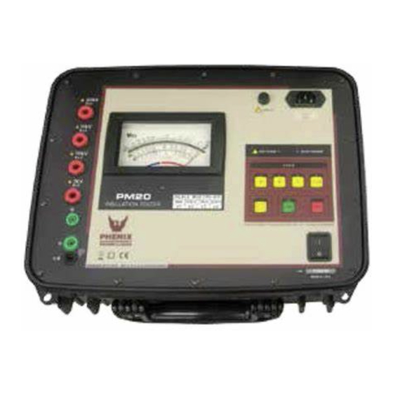
Summary of Contents for Phenix Technologies PM-20
- Page 1 Phenix Technologies, Inc. 75 Speicher Drive Accident, Maryland 21520 PM-20 High Voltage Insulation Tester User Guide GU-1505RA ©Phenix Technologies, Inc. All rights reserved. PM-20...
- Page 2 DANGER / WARNINGS Complete Grounding of this unit is necessary for the safe operation of this equipment. Disconnect inputs before un- grounding this equipment PM-20...
- Page 3 DO NOT operate damaged equipment. Remove power, and do not use the equipment until safe operation can be verified by service-trained personnel. Phenix Technologies, Inc. assumes no liability for unsafe or improper use of test equip- ment. PM-20...
- Page 4 PM-20 Safety Warnings Before using this instrument, this manual and Safety Warnings must be read and understood. Observe Safety procedures and rules for working near high voltage energized systems during the use of this equipment. The generated voltages may be dangerous.
-
Page 5: Table Of Contents
4. High Voltage Indicator ............. 9 5. Operating Instructions ........... 10 6. Polarization Index (PI) ........... 12 7. Infinite Setting ............... 12 8. Replacement Fuse ............13 9. Cleaning ................ 13 10. Technical Specifications ..........14 11. Application Note 32 ............. 15 PM-20... -
Page 6: Description
1. Description The PM-20 high-voltage insulation tester is a truly portable device that allows measurements of insulation resistances using test voltages up to 20kV. It employs state-of-the-art technology for safe measurements of insulation resistances up to 4,000,000 MΩ with 4 test voltages: 5kV - 10 kV - 15 kV - 20 kV. -
Page 7: Measurements
5. 10 kV TEST VOLTAGE. 14. BATTERY CHARGER indicator. 6. 5 kV TEST VOLTAGE. 15. BATTERY CHECK key. 7. CURRENT RETURN terminal (-R). 16. ON/OFF switch. 8. GUARD terminal (G). 17. START key. 9. ANALOG indicator. 18. STOP key. PM-20... -
Page 8: Power Supply
However, the battery could be damaged if it remains in deep discharge for long periods. To avoid this effect, charge the battery before storing the equipment, and recharge within 30 days, even if the instrument was not used (under storage, the battery loses part of its charge). PM-20... -
Page 9: High Voltage Indicator
STOP key, the equipment will start discharging the potentials accumulated in the unit, internal capacitances, and in the element under test as well. When this dis- charging process is over, the high voltage led will turn off automatically. The test leads may then be disconnected. PM-20... -
Page 10: Operating Instructions
1. Connect the red test lead to the 20 kV, 15 kV, 10 kV or 5 kV terminal in accordance with the desired test voltage. 2. Connect the black test lead to the -R terminal. (The test leads in the drawings are only for illustration.) The green GUARD (G) terminal is not always used. PM-20... - Page 11 When this discharging process is over (up to 60 seconds after turn off), the High voltage will turn off automatically. The test leads may be disconnected. To finish measurement press On/Off switch. PM-20...
-
Page 12: Polarization Index (Pi)
The pointer should stay on the right end of the scale just over the infinite mark on scale C. In other cases, the plastic screw at the bottom of the galvanometer acrylic cover shall be adjusted. PM-20... -
Page 13: Replacement Fuse
Fuse Schurter, model SPT 5x20 (Time-lag) 2A/250V. High breaking capacity. 9. Cleaning To clean this instrument, use a soft cleaning anti-static liquid, after verifying that it doesn’t affect the plastic parts used in the case and in the Control Panel of this equipment PM-20... -
Page 14: Technical Specifications
: 95% RH (non condensing) Weight : Approx. 9.8 kg Dimensions : 378 x 308 x 175 mm Supplied accessories : 2 measuring test leads (1.80 m). GUARD test lead (1.80 m). Charger power cord. Carrying case User’s guide. PM-20... -
Page 15: Application Note 32
A typical example of this situation occurs when the insulation resistance between primary and secondary windings of a transformer mounted inside a metal housing is to be measured. Rx: Insulation resistance between primary and secondary winding. R1: Insulation resistance between primary winding and housing. R2: Insulation resistance between secondary winding and housing. PM-20... - Page 16 3,000 MΩ and R1 = R2 = 100 MΩ, the reading without using the GUARD terminal would be 187.5 MΩ, which is quite wrong. On the other hand, if the GUARD terminal is properly used, we would have 3,000 MΩ, with an error lower than 10%. PM-20...


Need help?
Do you have a question about the PM-20 and is the answer not in the manual?
Questions and answers