Table of Contents
Advertisement
Quick Links
Advertisement
Table of Contents

Related Manuals for Phenix Technologies HC-5


Summary of Contents for Phenix Technologies HC-5
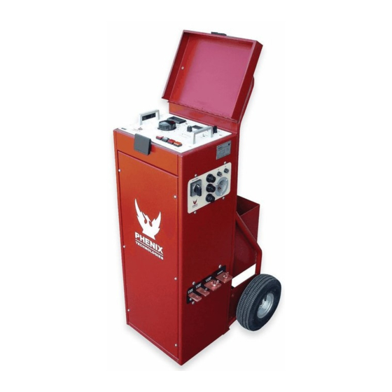
- Page 1 PORTABLE HIGH CURRENT TEST SET MODEL NUMBER HC-5 Version 5.0 FEB 17, 2012...
- Page 2 INTRODUCTION The HC-5 is a portable high current test set built for field and shop use. Designed using the latest technology, the HC-5 combines a variable high current output with appropriate controls and instrumentation for testing thermal, magnetic, and solid-state motor overload relays, molded-case circuit breakers, and ground fault trip devices.
-
Page 3: Table Of Contents
TABLE OF CONTENTS Section Number DANGER TECHNICAL SPECIFICATIONS WARNING THEORY OF OPERATION BASIC APPROACH TO TESTING CALIBRATION ELECTRICAL SCHEMATICS PARTS LIST PARTS ORDERING INFORMATION RETURNED MATERIAL... - Page 4 DO NOT operate damaged equipment. Remove power, and do not use the • equipment until safe operation can be verified by service-trained personnel. Phenix Technologies, Inc. assumes no liability for unsafe or improper use of test equipment.
-
Page 5: Technical Specifications
HC-5 TECHNICAL SPECIFICATIONS INPUT: 220-240 Volts, 50 Amps - Delay 50 Hz or 60 Hz (must be preset) OUTPUT: 0-15 Volts, 0-333 Amps 0-10 Volts, 0-500 Amps 0-5 Volts, 0-1000 Amps OVERLOAD: Short duration overloads are possible on each tap. The test set is capable of up to 5000+ amps, depending on the impedance of the test circuit. -
Page 6: Warning
WARNING 1. For safe operation, it is important that the unit be plugged into a properly grounded receptacle. 2. This unit is not designed for use in energized circuits. 3. Due to leakage current within the solid-state circuitry, it is strongly recommended to turn control power off when changing the output leads. -
Page 7: Theory Of Operation
THEORY OF OPERATION The following is a listing of the controls, switches, and lamps on the control panels and a description of their functions. INPUT Input cable plugs in here to provide input power. MAIN POWER This controls the input power to the control and the power section, and provides power circuit protection. - Page 8 THEORY OF OPERATION SENSE SWITCH This can be set to CONTACTS or CURRENT mode. When placed in CONTACTS mode, the unit will react to a change in condition of the SENSE INPUTS (Normally Open to Normally Closed, or Normally Closed to Normally Open).
- Page 9 THEORY OF OPERATION TIMER The timer will begin counting when HC ON is pressed and the current surpasses the 9% or 4% level. The timer will stop when the current drops below the 9% or 4% level in the SENSE CURRENT mode. When in the SENSE CONTACTS mode, the timer will stop when a change in the SENSE INPUTS is detected.
-
Page 10: Basic Approach To Testing
BASIC APPROACH TO TESTING The HC-5 is basically a continuously variable high current source, the magnitudes of which are dependent on the output tap which is selected. Please refer to the Technical Data and Specifications for the voltage and current ratings of the taps. -
Page 11: Calibration
CALIBRATION TIMER The timer is run from a precision programmable oscillator and should never require calibration. CURRENTMETER The calibration of the currentmeter should be checked on a yearly basis. To do this, place the MEM/CONT switch in the CONT position. Place the range switch in the 2 AMP range. -
Page 12: Electrical Schematics
ELECTRICAL SCHEMATICS Drawing Number Description 1. 9304535 Sheet 1 HC-5 Electrical Schematic... -
Page 13: Parts List
Resistor, 1kOhm, 10W 31136100 PCB1361 PCB1361: HC CNTRLS AND PWR ASSY 1151955 J1,J2 JUMP-JAX ROHS 31122306 PCB1223 PCB1223 ASSY FOR HC-5 1721700 R206 Resistor, 910 Ohm, .5W, 1% 1722091 R207 Resistor, 3.65 kOhm, .5W, 1% 1860120 SW1,3,4,5 Switch, HC ON, OFF, JOG, RESET... -
Page 14: Parts Ordering Information
When your purchase order is received at our office, a representative of Phenix Technologies will contact you to confirm the current price of the part being ordered. If a part you order has been replaced with a new or improved part, an Applications Engineer will contact you concerning any change in part number. -
Page 15: Returned Material
Serial Number Reason for Return Cause of Defect If Phenix Technologies, Inc. deems return of the part appropriate, it will then issue an "Authorization for Return". If return is not deemed advisable, other inspection arrangements will be made. NOTE: Material received at this plant without the proper authorization shall be held as "Customer's Property"...
Need help?
Do you have a question about the HC-5 and is the answer not in the manual?
Questions and answers