
Related Manuals for Phenix Technologies 660-10P


Summary of Contents for Phenix Technologies 660-10P
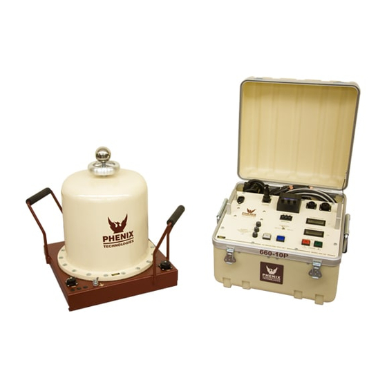
- Page 1 Users Manual Phenix Technologies Inc. VACUUM INTERRUPTER TEST SET Model Number 660-10P Version 3.2...
-
Page 3: Table Of Contents
TABLE OF CONTENTS Section Number GENERAL SAFETY PRECAUTIONS SPECIFICATIONS CONTROL AND METERING DESCRIPTION CONNECTIONS AND GROUNDING OPERATION INSTRUCTIONS RECALIBRATION PARTS LIST MAINTENANCE RETURNED MATERIAL PARTS ORDERING INFORMATION RECOMMENDED SPARE PARTS ANSI C37.60 SPECIFICATIONS ELECTRICAL SCHEMATICS... -
Page 4: General Safety Precautions
DO NOT operate damaged equipment. Remove power, and do not use the equipment until safe operation can be verified by service-trained personnel. Phenix Technologies, Inc. assumes no liability for unsafe or improper use of test equipment. -
Page 5: Specifications
SPECIFICATIONS GENERAL SPECIFICATIONS Tests up to 24.9 kV class interrupters in accordance with ANSI C37.60 specifications Portable two-piece unit Rugged construction for field use Security/Safety interlock circuit Digital, direct-reading output kilovoltmeter with memory feature Digital, direct-reading output currentmeter ... -
Page 6: Control And Metering Description
CONTROL AND METERING DESCRIPTION (Paragraphs are keyed to FIGURE 1) 1. Auto Voltage Preset. Press (+) and (-) buttons to select desired test level. Range 00.0 to 60.0 kV. 2. SX1 Connector. Provision for connecting external interlocking switching loop. Open loop prevents high voltage turn on. - Page 7 Figure 1...
-
Page 8: Connections And Grounding
CONNECTIONS AND GROUNDING Position set in the desired location. Ground set by use of ground terminal on base of high voltage transformer. Connect TX1 and TX2 cables between controls and high voltage transformer. Connect SX1 - external interlock circuit as appropriate. ... -
Page 9: Operation Instructions
OPERATION INSTRUCTIONS 1. Check connections, power and ground to test set and specimen under test (refer to ANSI C37-60). 2. Turn on control power. 3. Select the desired voltage test level. 4. Select the desired rate of rise. 5. Select the desired dwell time (1-999 seconds). 6. -
Page 10: Recalibration
RECALIBRATION DO NOT ATTEMPT THIS CALIBRATION UNLESS QUALIFIED TO WORK ON ENERGIZED HIGH VOLTAGE TEST EQUIPMENT!! Voltmeter-Normal Mode 1. Connect a standard voltmeter with a range of 0-60 kVAC from the high voltage terminal of the test transformer to ground. 2. - Page 11 RECALIBRATION Locate Current Output Adjustment calibration potentiometer, R1, on (A3) PCB 1078. Turn on high voltage and raise output until 10 milliamperes is read on standard meter. Adjust currentmeter calibration potentiometer until panel meter agrees with standard. Raise and lower output and compare panel meter with standard at various points. Shut off high voltage and disconnect standard meter.
-
Page 12: Parts List
PARTS LIST ITEM DESCRIPTION PART NO. Control Unit PCB1150 PCB 1150 Assy 31115011 PCB1023 PCB 1023 Autovoltage Ckt 31102301 PCB1020 PCB 1020 Overcurrent Ckt 31102002 PCB1078 PCB 1078 Currentmeter Ckt 31107813 PCB1175 PCB 1175 Voltmeter Ckt 31117505 Motor / Variac Assy MOTOR Motor Bodine 744KC-22T5 1560715... - Page 13 PARTS LIST PCB1150 A1-A4 PCB Connector 22-P-Card Edge 1152565 A1-A4 Card Edge Guides 1152571 C1,2 Capacitor 1000uf 50V Elect 1098940 C3,4,6 Capacitor 2.2uf 50V 1094438 Capacitor 3300uf 25V Elect 1099331 C7,8 Capacitor .1uf 20V 1093020 C9,10,11 Capacitor .01uf 1kV 1092050 X1,2,3 8 Pin Phoenix Conn &...
- Page 14 PARTS LIST Miscellaneous M1 Protection Bd Voltmeter Surge Protection Board 31126501 M2 Protection Bd Currentmeter Surge Protection Board 31126500 TX1 Cable Complete TX1 Cable (Power) 30110013 TX1 Cable High Current Plug, Female Pins 1151180 TX1 Cable High Current Plug, Male Pins 1151181 TX1 Cable High Current Pins, Male...
-
Page 15: Maintenance
MAINTENANCE No solution or chemical stronger than ordinary mild soap and water solution should be applied to the cabinet area of this unit. Care must be used when cleaning the meter faces and console panel. Abrasives may remove printing and descriptive titles and scratch meter faces. When cleaning, always have unit disconnected from power source. -
Page 16: Returned Material
Serial Number Reason for Return Cause of Defect If Phenix Technologies, Inc. deems return of the part appropriate, it will then issue an "Authorization for Return". If return is not deemed advisable, other inspection arrangements will be made. NOTE: Material received at this plant without the proper authorization shall be held as "Customer's Property"... -
Page 17: Parts Ordering Information
When your purchase order is received at our office, a representative of Phenix Technologies will contact you to confirm the current price of the part being ordered. If a part you order has been replaced with a new or improved part, an Applications Engineer will contact you concerning any change in part number. -
Page 18: Recommended Spare Parts
10-1 RECOMMENDED SPARE PARTS In order to maintain your set in full operating condition with a minimum of down time, the following spare parts should be kept on hand to avoid unnecessary phone calls, expensive modes of shipment, delays in repairs, etc. Pricing is available upon request. Quantity Description Part Number... - Page 19 11-1 ANSI C37.60-1981 Standard Requirements for Overhead, Pad Mounted, Dry Vault and Submersible Automatic Circuit Reclosers and Fault Interrupters for AC Systems. Copies of standards may be obtained from: The Institute of Electrical and Electronic Engineers, Inc. 345 East 47th Street New York, NY 10017 (800)678-IEEE...
-
Page 20: Electrical Schematics
12-1 ELECTRICAL SCHEMATICS Drawing Number Description 1. 31117505 Peak Detector Circuit (PC 1175) 2. 31102002 Overload Circuit (PCB 1020) 3. 31107813 Digital Meter Circuit (PCB 1078) 4. 31102301 Auto/Overvoltage Circuit (PCB 1023E) 5. 9607029 Oil Vacuum Interrupter Test Set (120V) 6.
Need help?
Do you have a question about the 660-10P and is the answer not in the manual?
Questions and answers