
Related Manuals for Phenix Technologies BK130


Summary of Contents for Phenix Technologies BK130
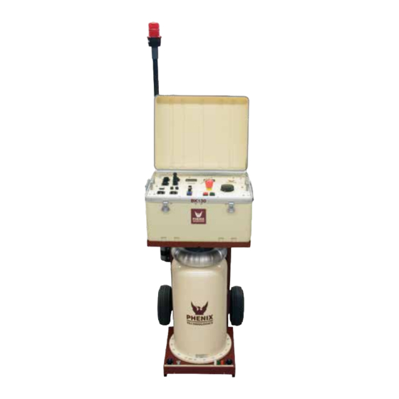
- Page 1 USER’S MANUAL AC DIELECTRIC TEST SET 600 SERIES Model Number BK130/36 Version 5.1 Phenix Technologies, Inc 75 Speicher Drive Accident, Maryland 21520 Copyright © Phenix Technologies, Inc. Rev 2/9/2015 nab BK-130...
- Page 2 DANGER BK-130...
- Page 3 DO NOT operate damaged equipment. Remove power, and do not use the equipment until safe operation can be verified by service-trained personnel. Phenix Technologies, Inc. assumes no liability for unsafe or improper use of test equipment. BK-130...
-
Page 4: Table Of Contents
TABLE OF CONTENTS DESCRIPTION SECTION NUMBER DANGER / GENERAL SAFETY PRECAUTIONS TECHNICAL SPECIFICATIONS UNCRATING PROCEDURE CONTROLS AND INDICATORS INITIAL SET-UP--MECHANICAL/ELECTRICAL OPERATIONAL VERIFICATION / GENERAL TEST GROUND/GUARD/RETURN CONNECTIONS CALIBRATION TROUBLESHOOTING MECHANICAL MAINTENANCE CHECKING OIL PURITY / SPECIFICATIONS TRANSPORTING/STORAGE OF EQUIPMENT CIRCUIT DIAGRAM SYMBOLS ELECTRICAL DIAGRAMS PARTS ORDERING INFORMATION RECOMMENDED SPARE PARTS... -
Page 5: Technical Specifications
SECTION 1: TECHNICAL SPECIFICATIONS Input 110 - 120 volts, single phase 50 / 60 Hz, 30 amperes 208 - 240 volts, single phase 50 / 60 Hz, 15 Amperes (Refer to Serial Tag for voltage and current designation) Output Rating 0-36 kilovolts, 180 milliamperes 0-130 kilovolts, 50 milliamperes Duty Cycle –... -
Page 6: Uncrating Procedure
SECTION 2: UNCRATING PROCEDURE 1. Exercise care in removing shipping materials so as not to damage unit. 2. Perform visual inspection to determine if unit was damaged during shipment. If there are any signs of physical damage (such as dents, scratches, oil leaks), contact the factory before proceeding. -
Page 7: Controls And Indicators
SECTION `3: CONTROLS AND INDICATORS Control Section FIGURE 3-1 BK-130... -
Page 8: Controls And Indicators
CONTROLS AND INDICATORS Descriptions are keyed to Figure 3-1. Main Power Indicator. Main Power Circuit Breaker. Interrupts all power into set. F1(120V) F1,2 (220V) - Control Power Fuse/Fuses. Transformer Power Circuit Breaker - Interrupts power to HV Transformer. Breaker must be on to activate High Voltage. - Page 9 CONTROLS AND INDICATORS FIGURE 3-2 BK-130...
- Page 10 CONTROLS AND INDICATORS High Voltage Section Descriptions are keyed to Figure 3-2. Power Connector – Power Cable from Output to Transformer connector, connects here. High Voltage Unit Ground Point - A Ground cable from facility ground or earth ground must be connected here.
-
Page 11: Initial Set-Up--Mechanical/Electrical
SECTION 4: INITIAL SET-UP—MECHANICAL / ELECTRICAL 1. Set up Bucket Truck or object under test. If testing a Bucket Truck, it is recommended to place outriggers and tires on insulating pads. CAUTIONj: When setting up the Bucket Truck, ensure that there are no overhead safety hazards such as live power lines. - Page 12 INITIAL SET-UP--ELECTRICAL WARNING: Ground the output of the High Voltage Transformer until set-up is complete! Be sure the Main Power Circuit Breaker is in the OFF position before proceeding. This equipment should only be operated by personnel familiar with High Voltage Testing and Safety Procedures The following are examples of basic setups for performing various tests using the PHENIX test set.
- Page 13 INITIAL SET-UP--ELECTRICAL Figure 4-1 BK-130...
- Page 14 INITIAL SET-UP--ELECTRICAL Connections for testing Category C Aerial Devices (REFER TO FIGURE 4-2 1. Connect the ground stud on the high voltage transformer to a good earth ground using the supplied lead. 2. Connect the ground stud on the high voltage transformer to the ground stud on the control cabinet using the supplied lead.
- Page 15 Initial Setup Electrical Figure 4-2 BK-130...
- Page 16 INITIAL SET-UP--ELECTRICAL Connections For Testing Chassis Insulators On Aerial Devices (Refer To Figure 4-3) 1. Connect the ground stud on the high voltage transformer to a good earth ground using the supplied lead. 2. Connect the ground stud on the high voltage transformer to the ground stud on the control cabinet using the supplied lead.
- Page 17 INITIAL SETUP ELECTRICAL (Figure 4-3) BK-130...
- Page 18 SECTIION 5: OPERATIONAL VERIFICATION PROCEDURE WARNING This equipment should only be used by personnel familiar with High Voltage Testing and Safety Procedures. 1. Make sure that Main Power Circuit Breaker on the Control Panel is in OFF position. 2. Make sure that all electrical connections have been properly made between the Controls and High Voltage Unit, including grounds.
- Page 19 OPERATIONAL VERIFICATION PROCEDURE 14. Move short from 36 kV output to 130 kV output and ground. Set Measurement Divider Switch to 36 kV / 180 mA. Repeat step 13. Unit should trip off at approximately 4.6 mA. NOTE: Do not attempt to check 110% level of current trip under shorted output conditions. Rated output currents are only available through a capacitive load of sufficient value.
- Page 20 GENERAL TEST PROCEDURE 1. Make sure that Main Power Circuit Breaker on the Control Panel is in the Off position. 2. Make sure that all electrical connections have been properly and securely made and that the test specimen is properly connected to the High Voltage Transformer (refer to Initial Set-up Procedures). Make sure the Guard / Ground / Return Jumper Clip is set properly for test being performed.
- Page 21 SECTION 6: GUARD-GROUND-RETURN CONNECTIONS The base of the High Voltage transformer contains a currentmeter feature useful in measurement of different current sources. (Refer To Figure 6-1) Standard Mode (RTN) (Use for liner testing) The standard configuration is set up to measure the current from the high potential side of the unit under test to ground.
- Page 22 GUARD-GROUND-RETURN CONNECTIONS Figure 6-1 BK-130...
-
Page 23: Calibration
SECTION 7: CALIBRATION CAUTION Calibration should only be done by persons familiar with High Voltage testing and safety procedures. All calibrations have been done at the factory. Periodic calibration of the output voltmeter and output currentmeter should be done approximately every six months. NOTE: Refer to Electrical Diagram Section for schematics pertaining to the model number of your test set. - Page 24 CALIBRATION Overcurrent This calibration should not need adjustment (factory adjusted). If the Overcurrent Circuit is out of calibration, perform the following steps. To recalibrate the Overcurrent Circuit with the High Voltage Unit it will be necessary to connect a 15 – 20 nanofarad capacitor rated at 36 kVAC or higher to the 36 kV / 180 mA output of the High Voltage Unit.
-
Page 25: Troubleshooting
Check main facility input power to the test set. Check all control and switch settings. Check indicating lamps. (Spare lamps are available through Phenix Technologies.) Check Fuse F1/F1, F2 Check operation of main power circuit breaker (CB1). Main Power lamp should be on. -
Page 26: Troubleshooting
TROUBLESHOOTING Specific Problems (Cont’d) Currentmeter inoperable? Binding post jumper clip installed between ground and guard with a grounded test object. Connection between currentmeter and high voltage test specimen return connected improperly. Meter damaged Faulty, TX1 interconnect cable. ... -
Page 27: Mechanical Maintenance
SECTION 9: MECHANICAL MAINTENANCE General No solution or chemical stronger than an ordinary household cleaner should be applied to the cabinet area of this unit. Care must be used when cleaning console panel. Abrasives may remove printing and descriptive titles. When cleaning, always have unit disconnected from power source. Never attempt to clean inside the unit as the cleaning solution may cause damage to the electronic components. -
Page 28: Checking Oil Purity / Specifications
SECTION 10: CHECKING OIL PURITY NOTE: Typical test data for the oil used by Phenix Technologies are provided at the end of this section. 1. The most reliable means of determining the purity of the oil in the field is to test the dielectric strength. Test sets for this purpose available on the market differ in design, particularly in the shape of the electrodes and the test container. - Page 29 10-2 CHECKING OIL PURITY 4. Oil Specifications Transformer oil is a high quality insulating oil specially refined and formulated to meet the exacting requirements of major electrical equipment manufacturers and users. It also meets Federal Specification VV-I- 530a. High quality mineral-based transformer oil is recommended as the insulating and cooling medium for oil- immersed transformers.
- Page 30 10-3 CHECKING OIL PURITY Typical Test Data for Transformer Oil TEST METHOD UNITS SPECIFICATION Moisture ASTM D1533 Mg/kg 35 max Color ASTM D1500 ASTM 0.5 max DDF (Power Factor) @100ºC ASTM D924 0.3 max 0.3 max Breakdown voltage (2mm gap) ASTM D1816 35 min Inhibitor Content...
-
Page 31: Transporting/Storage Of Equipment
11-1 SECTION 11: TRANSPORTING / STORAGE OF EQUIPMENT In some instances there is a requirement for transporting the equipment from one location to another for on- site field testing. If such conditions prevail, the following precautions should be adhered to. 1. -
Page 32: Circuit Diagram Symbols
12-1 SECTION 12: CIRCUIT DIAGRAM SYMBOLS CIRCUIT DIAGRAM SYMBOLS SYMBOLES POUR SCHEMA DE CIRCUIT SYMBOLE ZU SCHEMA SYMBOL DESCRIPTION DESCRIPTION BEMENKUNG Amplifier Unite d'amplificateur Verstarker ARSR Surge Arrestor Parafoudre Ueberspannungsableiter Capacitor Condensateur Kondensator BSHG Bushing Tranversee Durchfuehoung Electrolytic Capacitor Condensateur electrol Eleckrolytik kondensator Fuse Fusible... -
Page 33: Electrical Diagrams
13-1 SECTION 13: ELECTRICAL DIAGRAMS Drawing Number Description 9602130 - 120 V BK130 Electrical / PCB 1257 9602132 - 220 – 240 V BK130 Electrical / PCB 1257 BK-130... -
Page 34: Parts Ordering Information
When your purchase order is received at our office, a representative of Phenix Technologies will contact you to confirm the current price of the part being ordered. If a part you order has been replaced with a new or improved part, an Applications Engineer will contact you concerning any change in part number. -
Page 35: Recommended Spare Parts
If the unit will be operated at an isolated site for an extended period or will be subjected to unusual stresses, a larger quantity of parts should be stocked as spares. In such a case, contact your Phenix Technologies' sales representative for a recommendation. -
Page 36: Parts List
16-1 `SECTION 16: BK -130 PARTS LIST Bubble No Part Number Description Quantity CONTROL SECTION CB1 (120 V) 1601330 AM1-A3-A-30-2,250V 1 Pole Breaker CB1 (220 V) 1601317 AM2-A3-A-15-2, 250V 2 Pole Breaker CB2 (120 V) 1601332 30 AMP 2 POLE BREAKER CB2 (220 V) 1601317 AM2-A3-A-15-2, 250 V 2 Pole Breaker... -
Page 37: Optional Accessories
PCB 1223 2” POLISHED STAINLESS STEEL BALL S.S. BALL 2403120 OPTIONAL ACCESSORIES STROBE LIGHT & 48660005 TELESCOPING STROBE LIGHT ASSY. POLE ALUMINUM COVER 9607031 ALUMINUM COVER Contact the Phenix Technologies Service Department Customer Service Coordinator for pricing of accessories. BK-130... -
Page 38: Returned Material
Serial Number Reason for Return Cause of Defect If Phenix Technologies, Inc. deems return of the part appropriate; it will then issue an "Authorization for Return." If return is not deemed advisable, other inspection arrangements will be made. NOTE: Material received at this plant without the proper authorization shall be held as "Customer's Property"... -
Page 39: Customer Comments / Suggestions
18-1 SECTION 18: CUSTOMER COMMENTS/SUGGESTIONS Phenix Technologies made significant efforts to ensure that the materials in this Operator’s Manual are correct. If there are concerns or comments as you have used this information, Phenix Technologies appreciates any feedback. Unit Serial Number.
Need help?
Do you have a question about the BK130 and is the answer not in the manual?
Questions and answers