
Related Manuals for H3C MSR3610-I Series


Summary of Contents for H3C MSR3610-I Series
- Page 1 H3C MSR3610-I ICT Converged Gateway Series Installation Guide New H3C Technologies Co., Ltd. http://www.h3c.com Document version: 6W104-20201231...
- Page 2 The information in this document is subject to change without notice. All contents in this document, including statements, information, and recommendations, are believed to be accurate, but they are presented without warranty of any kind, express or implied. H3C shall not be liable for technical or editorial errors or omissions contained herein.
- Page 3 Preface This installation guide describes the installation procedure for the H3C MSR3610-I ICT converged gateway series. It covers installation preparation, device installation, hardware replacement, and troubleshooting. This preface includes the following topics about the documentation: • Audience. • Conventions. •...
- Page 4 Symbols Convention Description An alert that calls attention to important information that if not understood or followed WARNING! can result in personal injury. An alert that calls attention to important information that if not understood or followed CAUTION: can result in data loss, data corruption, or damage to hardware or software. An alert that calls attention to essential information.
- Page 5 Documentation feedback You can e-mail your comments about product documentation to info@h3c.com. We appreciate your comments.
-
Page 6: Table Of Contents
Contents 1 Preparing for installation ············································································· 1 Safety recommendations ··································································································································· 1 Safety symbols ··········································································································································· 1 General safety recommendations ·············································································································· 1 Electricity safety ········································································································································· 1 Laser safety ················································································································································ 2 Examining the installation site ···························································································································· 2 Temperature and humidity ························································································································· 2 Cleanliness ················································································································································· 2 Cooling ·······················································································································································... - Page 7 Solution ···················································································································································· 26 No response from the serial console port ········································································································ 26 Symptom ·················································································································································· 26 Solution ···················································································································································· 26 Interface module failure···································································································································· 26 Symptom ·················································································································································· 26 Solution ···················································································································································· 26...
-
Page 8: Preparing For Installation
Preparing for installation This document applies to the following models: • MSR3610-I-XS • MSR3610-IE-XS • MSR3610-I-DP • MSR3610-IE-DP • MSR3610-IE-ES • MSR3610-IE-EAD • MSR3610-I-IG • MSR3610-IE-IG Safety recommendations Safety symbols When reading this document, note the following symbols: WARNING means an alert that calls attention to important information that if not understood or followed can result in personal injury. -
Page 9: Laser Safety
Laser safety WARNING! Disconnected optical fibers or transceiver modules might emit invisible laser light. Do not stare into beams or view directly with optical instruments when the switch is operating. • Use the shutdown command to disable an interface before you remove a transceiver module from the interface. -
Page 10: Cooling
Table1-2 Dust concentration limit in the equipment room Substance Concentration limit (particles/m ≤ 3 x 10 Dust particles (No visible dust on desk in three days) NOTE: Dust particle diameter ≥ 5 µm The equipment room must also meet limits on salts, acids, and sulfides to eliminate corrosion and premature aging of components, as shown in Table1-3. -
Page 11: Emi
• Maintain the humidity and temperature in the equipment room in the acceptable range. • Always wear an ESD wrist strap and ESD garment when touching a circuit board or transceiver module. The device does not provide an ESD wrist strap, prepare it yourself. •... -
Page 12: Installation Tools And Accessories
• A minimum clearance of 0.8 m (2.62 ft) is reserved between the rack and walls or other devices for heat dissipation and maintenance. • The headroom in the equipment room is not less than 3 m (9.84 ft). Installation tools and accessories Figure1-2 Installation tools Flat-head Phillips... - Page 13 Item Requirements Result • MSR3610-I-XS/3610-IE-XS/3610-I-DP/3610-IE-DP/36 10-IE-ES/3610-IE-EAD: Without a drive: 0°C to 45°C (32°F to 113°F). With a drive: 5°C to 40°C (41°F to 104°F). Temperature • MSR3610-I-IG/3610-IE-IG: Without a drive: –20°C to +55°C (–4°F to +131°F) With a drive: 5°C to 40°C (41°F to 104°F) ...
-
Page 14: Installing The Device
• Keep the tamper-proof seal on a mounting screw on the chassis cover intact, and if you want to open the chassis, contact H3C for permission. Otherwise, H3C shall not be liable for any consequence. - Page 15 Figure2-1 Installation flowchart Start Mount the device on a workbench or in a 19-inch rack Connect the grounding cable (Optional) Install an M.2 SSD drive (Optional) Install SIC interface modules (Optional) Install a SATA drive (Optional) Connect interface cables Connect AC power cords (Optional) Connect a PoE adapter Verify the installation...
-
Page 16: Mounting The Device On A Workbench
Mounting the device on a workbench IMPORTANT: • Make sure the workbench is clean, stable, and reliably grounded. • Maintain a minimum clearance of 100 mm (3.94 in) around the device for heat dissipation. • Do not place heavy objects on the device. To mount the device on a workbench: Place the device upside down on the workbench and attach the rubber feet to the four round holes in the chassis bottom. -
Page 17: Mounting The Device In A Rack
Mounting the device in a rack Device dimensions and rack requirements Figure2-3 Device dimensions 60 mm Mounting bracket (2.36 in) E1 cable Power cord 60 mm 360 mm (2.36 in) (14.17 in) Table2-1 Device dimensions and rack requirements Chassis dimensions Rack requirements •... -
Page 18: Installing The Device In A Rack
Installing the device in a rack CAUTION: The mounting brackets can support only the weight of the device. Do not place objects on the device. To install the device in a rack: Use a mounting bracket to mark the cage nut installation holes in the front rack posts. Make sure the cage nut installation holes on the front rack posts are on a horizontal line. -
Page 19: Connecting The Grounding Cable
Figure2-6 Attaching mounting brackets to the device Use M6 screws to attach the mounting brackets on the device to the front rack posts. Figure2-7 Securing the device to the rack Connecting the grounding cable CAUTION: • Correctly connecting the grounding cable is crucial to lightning protection and EMI protection. When you install and use the device, first ground the device reliably. -
Page 20: Installing An M.2 Ssd Drive
Figure2-8 Connect the grounding cable Installing an M.2 SSD drive CAUTION: To use an M.2 SSD drive on the device, first install it on a SIC-M2-SATA riser module. To install an M.2 SSD drive: Insert the M.2 SSD drive into the M.2 slot on the SIC-M2-SATA riser module at a 45° angle. Slightly press the M.2 SSD drive until it is level with the surface of the connector. -
Page 21: Installing A Sata Drive
Figure2-10 Installing a SIC Installing a SATA drive CAUTION: • Always wear an ESD wrist strap when installing a SATA drive and hold the drive by its two sides. • Do not touch any components of the drive, or squeeze, shake, or strike the drive. No SATA drive is provided with the device. -
Page 22: Connecting Interface Cables
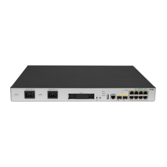
The fixed ports on the device are MDI/MDIX autosensing. You can use straight-through or crossover network cables to connect the ports. Examine the port LED on the device. For more information about the LEDs, see H3C MSR3610-I ICT Converged Gateway Series Hardware Information and Specifications. -
Page 23: Connecting An Ethernet Fiber Port
Connecting an Ethernet fiber port WARNING! Disconnected optical fibers or transceiver modules might emit invisible laser light. Do not stare into beams or view directly with optical instruments when the switch is operating. CAUTION: • Never bend an optical fiber excessively. The bend radius of an optical fiber must be not less than 100 mm (3.94 in). - Page 24 The following figure is for illustration only. The device provides two AC power receptacles. You can connect one AC power cord to power the device or two AC power cords for 1+1 redundancy. Connecting an AC power cord for an MSR3610-I-DP/3610-IE-DP/3610-IE-ES/3610-IE-EAD gateway Install the power cord retainer clip.
-
Page 25: Connecting A Poe Adapter
Connecting a PoE adapter IMPORTANT: • A PoE adapter is used only for PoE output. Before connecting a PoE adapter to the device, make sure the device is connected to an AC power source and is operating correctly. The device cannot operate correctly with only a PoE adapter connected to it. -
Page 26: Accessing The Device For The First Time
Accessing the device for the first time Connecting the console cable CAUTION: • To connect a PC to an operating device, first connect the PC end. To disconnect a PC from an operating device, first disconnect the device end. • If the PC does not have a RS-232 serial port but has a USB port, use a USB-to-RS-232 converter and install the corresponding driver for console cable connection. - Page 27 System is Starting ..Press Ctrl+D to access BASIC-BOOTWARE MENU Booting Normal Extend Bootware **************************************************************************** H3C MSR3610 BootWare, Version 1.02 **************************************************************************** Copyright (c) 2004-2017 New H3C Technologies Co., Ltd. Compiled Date : Dec 15 2017 09:17:12 CPU ID : 0x14 Memory Type...
-
Page 28: Replacement Procedure
• Keep the tamper-proof seal on a mounting screw on the chassis cover intact, and if you want to open the chassis, contact H3C for permission. Otherwise, H3C shall not be liable for any consequence. -
Page 29: Replacing A Sic Interface Module
Figure3-1 Removing the drive Use a Phillips screwdriver to remove the four fastening screws from the drive carrier. Pull the drive slowly out of the drive carrier. Keep the removed drive secure for future use. Figure3-2 Removing the drive carrier Install a new SATA drive. -
Page 30: Replacing An M.2 Ssd Drive
If you are not to install a new SIC, install a filler panel in the slot and fasten the screws on the filler panel. Figure3-3 Removing a SIC Replacing an M.2 SSD drive Remove the SIC-M2-SATA riser module. For more information about removing an SIC-M2-SATA riser module, see ''Replacing a SIC interface module."... -
Page 31: Troubleshooting
• Keep the tamper-proof seal on a mounting screw on the chassis cover intact, and if you want to open the chassis, contact H3C for permission. Otherwise, H3C shall not be liable for any consequence. -
Page 32: Fan Tray Failure
Verify that the fan tray is present. Verify that the no object has entered the chassis and gets stuck in the fan tray. If the fan tray stops rotating, contact H3C Support to replace the fan tray. If the issue persists, contact H3C Support. - Page 33 Verify that the Data bits field is set to 8 for the terminal. If the Data bits field is set to 5 or 6, the terminal displays garbled characters. If the issue persists, contact H3C Support. No response from the serial console port Symptom The console port on the device is connected to a serial port on a configuration terminal.
Need help?
Do you have a question about the MSR3610-I Series and is the answer not in the manual?
Questions and answers