
Related Manuals for H3C ICT Converged Gateway Series


Summary of Contents for H3C ICT Converged Gateway Series
- Page 1 H3C MSR3610-I ICT Converged Gateway Series Hardware Information and Specifications New H3C Technologies Co., Ltd. http://www.h3c.com Document version: 6W100-20201231...
- Page 2 The information in this document is subject to change without notice. All contents in this document, including statements, information, and recommendations, are believed to be accurate, but they are presented without warranty of any kind, express or implied. H3C shall not be liable for technical or editorial errors or omissions contained herein.
- Page 3 Preface This document provides hardware information and specifications for the H3C MSR3610-I ICT converged gateway. This preface includes the following topics about the documentation: • Audience. • Conventions. • Documentation feedback. Audience This documentation is intended for: • Network planners.
- Page 4 Symbols Convention Description An alert that calls attention to important information that if not understood or followed WARNING! can result in personal injury. An alert that calls attention to important information that if not understood or followed CAUTION: can result in data loss, data corruption, or damage to hardware or software. An alert that calls attention to essential information.
- Page 5 Documentation feedback You can e-mail your comments about product documentation to info@h3c.com. We appreciate your comments.
-
Page 6: Table Of Contents
Contents 1 Chassis views and technical specifications ·············································· 1-1 Chassis views ················································································································································· 1-1 MSR3610-I-DP/MSR3610-I-XS/MSR3610-IE-DP/MSR3610-IE-ES/MSR3610-IE-XS ···························· 1-1 MSR3610-IE-EAD ··································································································································· 1-2 MSR3610-I-IG/3610-IE-IG ······················································································································ 1-2 Power button ··········································································································································· 1-3 Technical specifications ·································································································································· 1-3 Link mode of interfaces ··································································································································· 1-4... -
Page 7: Chassis Views And Technical Specifications
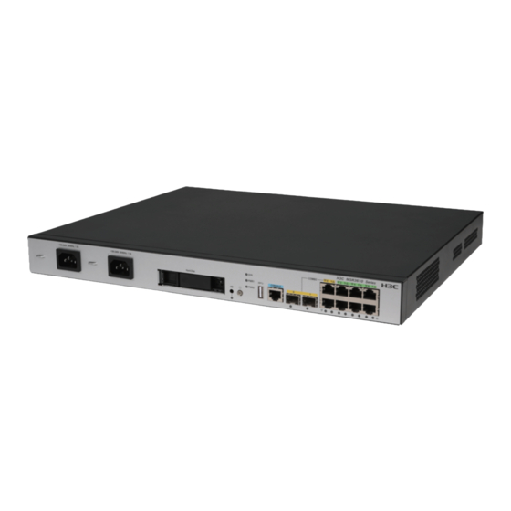
Chassis views and technical specifications Chassis views The following figures are for illustration only. The label Hard Disk on the front panel refers to a drive slot. MSR3610-I-DP/MSR3610-I-XS/MSR3610-IE-DP/MSR3610- IE-ES/MSR3610-IE-XS Figure1-1 Front panel (1) AC power receptacles PWR1 and PWR2 (2) Drive slot (3) Power button/LED (4) USB port (5) Console port (CONSOLE) -
Page 8: Msr3610-Ie-Ead
MSR3610-IE-EAD Figure1-3 Front panel (1) AC power receptacles PWR1 and PWR2 (2) Drive slot (3) Power button/LED (4) USB port (5) Console port (CONSOLE) (6) Ethernet fiber port SFP0 (combo interface) (7) Ethernet fiber port SFP1 (combo interface) (8) Ethernet copper ports GE0 and GE1 (combo interfaces) (9) Ethernet copper ports GE2 to GE7 (10) Drive button (HD) Figure1-4 Rear panel... -
Page 9: Power Button
Figure1-6 Rear panel (1) SIC interface module slots 1 to 4 (2) Grounding screw Power button WARNING! The device might still have power after you press the power button. Do not reboot the device or remove power cords from the device until the power button/LED goes off. CAUTION: •... -
Page 10: Link Mode Of Interfaces
MSR3610-IE-DP/36 MSR3610-I-DP/361 MSR3610-IE-E MSR3610-I-IG/36 Item 10-IE-ES/3610-IE-X 0-I-XS 10-IE-IG drive) drive) SIC interface module slots AC power receptacles • MSR3610-I-IG : 8 GB Memory 8/16/32 GB DDR4 8/16/32 GB DDR4 32 GB DDR4 • MSR3610-IE-I G: 16 GB • MSR3610-I-IG : 4 GB EMMC •... - Page 11 Table1-3 describes these interfaces. For information about link mode change of interfaces on interface modules, see H3C MSR Router Series Comware 7 Interface Module Guide. Table1-2 Fixed interfaces that can operate only as Layer 3 Ethernet interfaces Device model...
- Page 12 Contents 1 LEDs ········································································································ 1-1 LEDs ······························································································································································· 1-1 LED descriptions ············································································································································· 1-1...
- Page 13 LEDs LEDs Figure1-1 MSR3610-I-DP/3610-I-XS/3610-IE-DP/3610-IE-ES/3610-IE-XS/3610-IE-EAD LEDs (1) System status LED (SYS) (2) Power status LED (PWR1) (3) Power status LED (PWR2) (4) LEDs for Ethernet copper ports GE0 to GE7 (5) LEDs for Ethernet fiber ports SFP0 and SFP1 (6) Power button/LED (7) Drive LED (HD) Figure1-2 MSR3610-I-IG/3610-IE-IG LEDs (1) System status LED (SYS)
- Page 14 Status Description (SYS) The memory does not exist or system Slow flashing yellow initialization has failed. Fast flashing yellow The extended segment does not exist. The system hardware is faulty or the device has no power input. Steady green The SDRAM is performing self-test. The system software image is being Fast flashing green decompressed.
- Page 15 Status Description The port is receiving or transmitting data at 1000 Flashing green Mbps. Steady yellow A 100 Mbps link is present. Flashing yellow The port is receiving or transmitting data at 100 Mbps. No link is present. Steady green The hard disk has completed initialization.
- Page 16 Contents 1 Slot arrangement and interface numbering ················································· 2...
- Page 17 Slot arrangement and interface numbering The fixed ports on the device are defined in slot 0. The device provides four SIC slots. Table1-1 describes the slot arrangement and interface numbering of the device. Table1-1 Slot arrangement and interface numbering Slot arrangement Interface numbering An interface on a SIC interface module is numbered in the x/y format.
Need help?
Do you have a question about the ICT Converged Gateway Series and is the answer not in the manual?
Questions and answers