Bolin Technology D Series Manual
Dante av ptz camera
Hide thumbs
Also See for D Series:
- User manual (53 pages) ,
- Quick start manual (19 pages) ,
- User manual (27 pages)

Related Manuals for Bolin Technology D Series


Summary of Contents for Bolin Technology D Series
- Page 1 D Series DANTE AV PTZ Camera USER MANUAL Part One: Camera Use VERSION: D-09232021 DANTE AV CAMERA D412 © 2021 Bolin Technology...
-
Page 2: Table Of Contents
Contents IMPORTANT INFORMATION ..............................5 WHAT’S IN THE BOX ................................. 7 OVERVIEW ....................................8 FEATURES ....................................8 CAMERA DIAGRAMS ................................9 ..................................10 EMOTE ONTROLLER CAMERA INSTALLATION ................................. 11 ................................12 EILING OUNT NSTALLATION ................................13 OUNT NSTALLATION SYSTEM CONFIGURATION ............................... 14 .................................. - Page 3 — ....................37 TORING THE AMERA ETTINGS IN EMORY RESETTING EATURE MENU CONFIGURATION ................................. 41 TROUBLESHOOTING ................................43 WARRANTY .................................... 44 SUPPORT CONTACT INFO ................................ 45 DIMENSIONS ..................................46...
- Page 4 Before operating the unit, please read this manual thoroughly and retain it for future reference. Copyright Copyright 2015-2021 Bolin Technology all rights reserved. No part of this manual may be copied, reproduced, translated, or distributed in any form or by any means without prior consent in writing from our company.
-
Page 5: Important Information
IMPORTANT INFORMATION Legal Notice Attention: To ensure account security, please change the password after your first login. You are recommended to set a strong password (no less than eight characters). Password login does not apply to some models that do not need password login. - Page 6 The contents of this document are subject to change without prior notice. Any updates and content changes will be added to the subsequent new manual version. If there are any concerns, please contact Bolin Support Team at www.bolintechnology.com Website Reference and other information For related product information please visit Bolin Technology website https://bolintechnology.com/...
-
Page 7: What's In The Box
WHAT’S IN THE BOX Accessories (Optional) -
Page 8: Overview
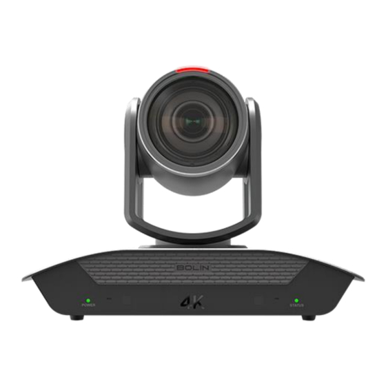
Overview This user guide is suitable for the following models: D412 Features • Dante AV powered by Dante AV Module, support Unicast or Multicast Dante AV video streaming over Standard 1Gbps Ethernet. • 1/2.8 Inch “Exmor R” CMOS sensor, Effective pixel number: 8.29 Megapixels. •... -
Page 9: Camera Diagrams
Camera Diagrams 1. 12V DC power port Connect the supplied DC power adaptor and cord. 2. Video format selector (For video format selection) 3. DIP switch 4. IR remote ID selector 5. IR receivers 6. MIC/LINE input ø 3.5 mm stereo mini jack, input impedance: high impedance During MIC input, supported mic: stereo mic (plug-in power) supply voltage: 2.5V ±... -
Page 10: Remote Controller
Remote Controller 1. MENU, on screen menu display ON/OFF 2. Camera IR ID Selector for Remote Control. 3. AI Features, available when AI button (13#) is pressed. (Set for fan speed adjustment) 4. Positioning Function and Number Buttons • Preset Position Calling and Setting 5. -
Page 11: Camera Installation
Camera Installation This device is designed for indoor use only. It is not designed to be used outdoors. Do not operate the device where it may meet constant heavy water. Please avoid installing the unit in a location commonly exposed to sunlight for extended periods of time. Do not install the unit near temperature adjustment device, such as a heating or cooling unit. -
Page 12: Ceiling Mount Installation
Ceiling Mount Installation Need to use Ceiling Mount bracket and M4*6PW/M3*6PW screws for this installation. Ceiling mount is sold separately. Please following the below diagrams for ceiling mount installation. Required accessories and components: Ceiling mount installation:... -
Page 13: Wall Mount Installation
Wall Mount Installation Need to use Wall Mount bracket and M4*6PW screws for this installation. Wall mount is sold separately. Please following the below diagrams for wall mount installation. Required accessories and components: Wall mount pendant installation: Wall mount standard installation... -
Page 14: System Configuration
System Configuration Connection The camera’s pan, tilt, zoom can be controlled with a keyboard controller by connecting a control cable (crossover cable, RS232, RS-422/485). The Dante AV decoder can be used to decode the Dante AV camera view and output it to a monitor via HDMI. -
Page 15: Obtain Video Signal
Obtain Video Signal The camera can simultaneously have HDMI and Dante AV IP video output. HDMI Video signal 1. Connect the camera to a UHD Monitor/TV using HDMI cable. 2. Turn on the camera, video will display on the monitor after initialization. 3. -
Page 16: Camera Control Methods And System Configurations
Camera Control Methods and System Configurations There are multiple ways of controlling the camera and various system configuration capabilities by using optional products. This section describes controlling methods with typical system examples and the required components of each. 1. Use the Infrared Remote Controller 2. - Page 17 You can make RS232 connection cable if you have the following applications: Use the included RJ45 to RS232 8 pin Mini Din adaptor to make RS232 connection for your control device. 10. Use the included RJ45 to RS422/232 Phoenix terminal contact adaptor to make RS232 connection for your control device.
-
Page 18: Use Rs-422(Visca)
12. How to make RS232 Daisy Chain multiple camera connection with standard RS232 serial port controller as below: Use RS-422(VISCA) You can use RS-422/485 port to connect optional controllers, such as joystick keyboard controller or PC control station, to operate the camera. To perform pan/tilt and zoom operations, use the joystick of the keyboard controller. - Page 19 SONY Keyboard RS422 Connection 10. How to make RS422 connection and RS422 Daisy Chain connection with Non-Sony controller as below: VISCA (Non-Sony) Keyboard RS422 Connection 11. Use included RJ45 to RS422 Phoenix connecter adaptor to make RS422 connection for your control device.
-
Page 20: Pelco P/D Keyboard Rs485 Connection
12. Or you can use CAT5/6 T-568B Standard Ethernet cable direct connect between the camera and the controller to make RS422 connection by following the pin definition below: 13. How to make RS422 Daisy Chain multiple camera connection with RS422 standard serial port controller: PELCO P/D Keyboard RS485 Connection NOTE: Use RS422 ports for RS485 connection. - Page 21 • Use joystick and Button “OPEN” or “CLOSE” to navigate OSD menu. • To operate keyboard, please refer to the user manual of the keyboard you are using. PELCO RS485 Connection • Use included RJ45 to RS422 Phoenix connecter adaptor to make RS485 connection for your control device. •...
-
Page 22: Visca Over Ip Control
Note For RS-232 VISCA control, this unit supports daisy chain connection for using multiple cameras. For control details, refer to Operating Instructions of control keyboard/station software. • You need to match the communication speed (Baud Rate) between the camera and the joystick controller. -
Page 23: Tally Light Gpi I/O Connection
Tally Light GPI I/O connection The camera is equipped with a Tally lamp that quickly distinguishes when the camera is in use. It is an arc Tally lamp used for improving visibility and merge together with the circular design lens. To use camera Tally Light function, you need a video switcher and a keyboard (not included). - Page 24 2. GPI I/O Output mode -Tally signal is sent by Keyboard Controller a. Connect camera with keyboard by standard RS-422 control cable. b. Access to KEYBOARD SETTING > GPI I/O > Setting, and change it to Output mode, then Exit to home directly.
-
Page 25: Dip Switch Settings
DIP SWITCH SETTINGS The Dip switch is for setting the camera configuration for following items: 1. Camera ID Address for VISCA protocol 2. RS-232 / RS-422 control method selection 3. RS-232 / RS-422 baud rate selection Setting of the DIP Switches Turn off power to the camera before changing the DIP switch settings. - Page 26 Setting of the back panel Rotate DIP Switches The Rotate Dip Switch is for setting video format. Use small screwdriver to turn the switch, the arrow points to the Numbers or the Letters. Please refer to the chart below to identify which video resolution corresponds with each Numbers & Letters. Numbers &...
-
Page 27: Adjusting And Setting With Menus
Adjusting and Setting with Menus About On-Screen Menus Various settings on the camera, like shooting conditions and system setup, can be changed while observing menus being displayed on a connected visual output device. This section explains how to read the on-screen menus before starting menu operations. The menu parameters may vary according to the different product model. -
Page 28: Exposure Menu
EXPOSURE Menu The EXPOSURE menu is used to set the items related to exposure. MODE (Exposure Mode) EXPOSURE MENU: FULL AUTO FULL AUTO: Iris, Gain and Shutter Speed can MODE FULL AUTO →EXPOSURE be set automatically. BACK LIGHT WHITE BALANCE MANUAL: Adjust the GAIN, electronic shutter EX-COMP. -
Page 29: White Balance Menu
exposure compensation level from the following: -7, -6, -5, -4, -3, -2, -1, 0, 1, 2, 3, 4, 5, 6, 7 If you set the level to 0, exposure compensation will be disabled. Level +7 is the brightest and –7 is the darkest compensation value. -
Page 30: Picture 1 Menu
PICTURE 1 Menu 2D NR: 2D Noise Reduction is a method of reducing noise within an image by comparing frame-to-frame, removing the variations that do not appear in each frame PICTURE MENU 3D NR 2D NR EXPOSURE 3D Noise Reduction is a method of reducing noise by 3D NR WHITE BALANCE comparing variances within the same frame, as well as... -
Page 31: Pan Tilt Zoom Menu
PAN TILT ZOOM Menu The PAN TILT ZOOM menu is used to select the PAN TILT ZOOM MENU pan/tilt/ zoom mode. DIGITAL ZOOM EXPOSURE DIGITAL ZOOM: ZOOM RATIO OSD WHITE BALANCE You can set digital zoom to ON or OFF. When set to VIDEO PARAMETERS PICTURE 1 OFF, digital zoom does not operate, and only optical... - Page 32 • MEMORY: Play or delete the recorded operations. Recording Trace Memory (pan/tilt/zoom operations) • Select the trace number you want to record in TRACE NO. • Move the cursor to RECORD and press the HOME button (or Joystick right click). *Setting menu (enter to record) is display at the top left corner of the screen •...
-
Page 33: System Menu
SYSTEM MENU PELCO ID SYSTEM MENU When using RS485 (PELCO P/D) control, Set EXPOSURE PELCO ID Camera ID to the address that you want to control WHITE BALANCE IR-RECEIVE to. This value is from 1-255. PICTURE 1 PRESET SETTINGS IR-RECEIVE (Infrared Signal Reception) PICTURE 2 COLOR SPACE YUV422... -
Page 34: Status Menu
NOTE: The firmware upgrade process is intended to be performed under the supervision of a BOLIN- Authorized repair technician. For assistance with this, please contact your authorized BOLIN Technology dealer, installer, or integrator. BOLIN Technology Technical Support can also be reached for assistance with this process... -
Page 35: Operation Using The Infrared Remote Controller
Operation Using the Infrared Remote Controller Pan/Tilt and Zoom Operation Panning and Tilting 1. Press the POWER switch. The camera will turn on and perform the pan/tilt reset operation automatically. 2. Press the arrow buttons to pan or tilt the camera. While checking the picture on the screen, press the desired arrow button. -
Page 36: Operating Multiple Cameras With Infrared Remote Controller
If the camera is moved forcibly, or a finger or other object interferes with camera movement, the camera may fail to memorize the pan/tilt position. Press the PAN-TILT RESET button to delete the pan/tilt position. Zooming Button (Slow Zoom) [T] - Zoom-IN and [W] - Zoom-OUT slowly Button (Fast Zoom) [T] - Zoom-IN and [W] - Zoom-OUT quickly Operating Multiple Cameras with Infrared Remote Controller 1. -
Page 37: Storing The Camera Settings In Memory - The Presetting Feature
Storing the Camera Settings in Memory — the Presetting Feature Memory (Preset) Using the preset function, 9 sets of camera shooting conditions can be stored and recalled. 9 sets of camera shooting conditions can be stored and recalled by using remote controller. Up to 128 presets via protocol programming. - Page 38 Adjusting the camera Adjusting the camera, including camera image parameter (Gain, Color, Contrast, White Balance (Red & Blue), Black Level), camera speed (Pan/Tilt speed, zoom speed and preset speed), as well as Freeze, Back Light and One Push White Balance. Gain-Adjust Gain Press Gain button, the Gain button light will on, then press “+”...
- Page 39 AI Feature Mode (Set to fan speed adjustment) Within Bolin Dante AV product line, this AI feature is set to adjust the speed of the fan that is built inside of the camera or decoder for heat dissipation. AI Button: Press AI button, the button is illuminated in blue color, the IR controller will switch to fan speed adjustment mode.
- Page 40 Changing Video Resolutions • Press and hold Fn button, then press the Resolution button to populate a menu where you can switch resolutions • Use the arrow keys to navigate • Press Home to select • Screen will show ‘CHANGING…” •...
-
Page 41: Menu Configuration
Menu Configuration The menus of camera are configured as described below. OSD Menu Configuration... -
Page 43: Troubleshooting
Troubleshooting Camera will not power on Use the supplied power adaptor or a proper rating PoE device. Verify wirings are properly connected and plugs are securely in place. If the camera is attached to an outlet with a power switch, please make sure the switch is on. Camera restarts by itself The camera may not be getting sufficient power. -
Page 44: Warranty
Warranty Disclaimer Bolin Technology in no event shall be liable to any party or any person for cases including but not limited to the ones below, except for reasonable replacement or maintenance of Bolin products. -
Page 45: Support Contact Info
Support Contact Info Your experience is important to us. If you need assistance, our support team can be reached by any of the methods below: • Go to https://bolintechnology.com/company/#contact-us and select customer support • Go to https://bolintechnology.com/support/ and use the Raise a Support Ticket button •... -
Page 46: Dimensions
Dimensions Unit: mm... - Page 47 2082 TECHNOLOGY LLC BOLIN TECHNOLOGY...
Need help?
Do you have a question about the D Series and is the answer not in the manual?
Questions and answers