Table of Contents
Advertisement
Quick Links
Advertisement
Table of Contents

Related Manuals for Festo CPX-4AE-4AA-H


Summary of Contents for Festo CPX-4AE-4AA-H
- Page 1 CPX-4AE-4AA-H Input module Operating instruc- tions 8159929 2021-06b [8159931]...
- Page 2 Translation of the original instructions CANopen , DeviceNet , EtherCAT , EtherNet/IP , HART , PI PROFIBUS PROFINET are registered ® ® ® ® ® ® trademarks of the respective trademark owners in certain countries.
-
Page 3: Table Of Contents
HART variables............25 Festo — CPX-4AE-4AA-H — 2021-06b... - Page 4 Technical data..............49 Festo — CPX-4AE-4AA-H — 2021-06b...
-
Page 5: About This Document
The product label is located on the top of the light guide è 4.3.2 Connection and display elements. Scanning the printed Data Matrix Code with an appropriate device opens the Festo Support Portal, with the information applicable for the product. Alternatively, the Product Key (11-digit alphanumeric code on the product labelling) can be entered in the search field of the Support Portal. -
Page 6: Specified Standards
Intended use The input module is intended solely for use in terminal CPX and terminal CPX-P of Festo. The input module is referred to as an analogue module in this document. – Operate the product only with suitable CPX bus nodes è Tab. 3 Suitable bus nodes/controllers and required revisions. -
Page 7: Training Of Qualified Personnel
The qualified personnel have skills and experience in dealing with electrical (open-loop) control technology. Additional information – Contact the regional Festo contact if you have technical problems è www.festo.com. – Accessories and spare parts è www.festo.com/catalogue. Product overview... -
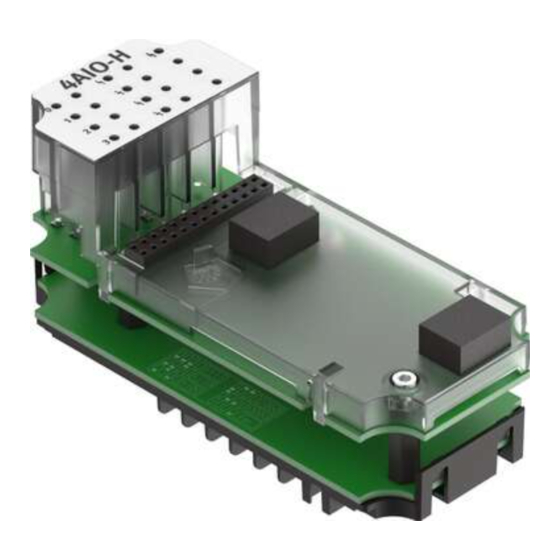
Page 8: Structure Of Analogue Module
– HART functionality in accordance with HART Communication Protocol Specification 7.5 – Support of the HART protocol in the versions 5, 6 and 7 Structure of analogue module Manifold block Electronics module Interlinking block with busbars Fig. 2: Structure of the analogue module — example Festo — CPX-4AE-4AA-H — 2021-06b... -
Page 9: Manifold Block
– For round plug M12x1 and SPEEDCON M12 – Screening possible using metal thread CPX-P-AB-4XM12-4POL Terminal manifold block – 2 pin headers COMBICON, 8-pin – For terminal strips in spring-loaded and screw terminal tech- nology CPX-P-AB-2XKL-8POL Tab. 6: Manifold blocks Festo — CPX-4AE-4AA-H — 2021-06b... -
Page 10: Connection And Display Elements
Highway Addressable Remote Transducer HART protocol Bidirectional, platform-independent data transfer protocol that permits access to the data of intelligent field devices Process image of inputs è process image. Process image of outputs è process image. Festo — CPX-4AE-4AA-H — 2021-06b... -
Page 11: Assembly
– The manifold block has a recess for a coding piece at the bottom. – Manifold block in pre-assembled CPX terminals are mechanically coded at the factory. Coding pin Fig. 4: Coding pin on the electronics module Festo — CPX-4AE-4AA-H — 2021-06b... - Page 12 4. Push the manifold block onto the electronics module without tilting until the coding piece in the manifold block engages. Removing coding piece from the manifold block To change the device configuration, the coding piece might have to be removed from the manifold block. Festo — CPX-4AE-4AA-H — 2021-06b...
-
Page 13: Mounting The Electronics Module And Manifold Block
Mounting the electronics module and manifold block Requirements – Supply voltage is switched off. – The interlinking block is clean and free of foreign matter. – DIL switches are set è Tab. 8 DIL switch settings. Festo — CPX-4AE-4AA-H — 2021-06b... - Page 14 2. Place the electronics module in the interlinking block without tilting. 3. Press the electronics module to the stop. 4. Align the manifold block on the interlinking block with the electronics module. 5. Push the manifold block onto the interlinking block without tilting. Festo — CPX-4AE-4AA-H — 2021-06b...
-
Page 15: Dismounting The Electronics Module And Manifold Block
CPX, e.g. if the process image is extended with HART variables. Switch setting Variant Description Without HART variables CPX-4AE-H 8 bytes 0 bytes Channel 0: input Channel 1: input Channel 2: input Channel 3: input Festo — CPX-4AE-4AA-H — 2021-06b... - Page 16 22 bytes 2 bytes Channel 0: input Channel 1: input Channel 2: input Channel 3: output CPX-2AE2AA-H + 4HV 20 bytes 4 bytes Channel 0: input Channel 1: input Channel 2: output Channel 3: output Festo — CPX-4AE-4AA-H — 2021-06b...
-
Page 17: Electrical
Notes on the cable connection – For the connection of HART field devices: observe the wiring requirements according to the HART specification. – Observe the maximum line lengths for the connection of field devices: 500 m. Festo — CPX-4AE-4AA-H — 2021-06b... -
Page 18: Attaching Connecting Cables To The Manifold Block M12
The metal thread of socket contact M12 is internally connected to the earth terminal of terminal CPX and can be used as a screen connection. – Only use suitable plugs è www.festo.com/catalogue. – Seal unused connections with protective caps ISK-M12 è Accessories. -
Page 19: Attaching Connecting Cables To The Manifold Block Terminals
AOUT X2.6 XGND X2.7 X2.8 XGND Tab. 10: Pin allocation on manifold block CPX-P-AB-2XKL-8POL Manifold blocks CPX-P-AB-2XKL-8POL do not have a connection for the cable screening. • Set up the screening or equipotential bonding separately. Festo — CPX-4AE-4AA-H — 2021-06b... - Page 20 [mm] Tab. 11: Specifications for spring-loaded terminal – Only use suitable terminal strips è www.festo.com/catalogue. – Connect only one conductor per spring-loaded terminal. – With a screwdriver, press the unlocking pin and insert the conductor end with the wire end sleeve into the terminal opening to the limit stop.
-
Page 21: Mechanically Coding The Terminal Connection
[mm] Tab. 12: Specifications for screw terminal – Only use suitable terminal strips è www.festo.com/catalogue. – Connect only one conductor per screw terminal. – Loosen the screw terminal, insert the conductor end with wire end sleeve and tighten the screw terminal (tightening torque: 0.5 …... -
Page 22: Connection Scenarios
2-wire connection of passive HART transmitters Fig. 12: 2-wire connection of a passive HART transmitter HART input module: active HART transmitter: passive Power supply for the HART transmitter, HART communication and actual values in the same circuit Festo — CPX-4AE-4AA-H — 2021-06b... -
Page 23: 3-Wire Connection Of Passive Hart Transmitters
HART input module: passive Auxiliary energy HART transmitter: active Power supply for the HART transmitter via auxiliary energy 6.5.4 2-wire connection of passive HART actuators Fig. 15: 2-wire connection of a passive HART actuator HART output module: active Festo — CPX-4AE-4AA-H — 2021-06b... -
Page 24: 4-Wire Connection Of Active Hart Actuators
IW CH2 IW CH1 IW CH0 6 bytes Output – – – SW CH3 2 bytes 2AE2AA-H Input – – IW CH1 IW CH0 4 bytes Output – – SW CH3 SW CH2 4 bytes Festo — CPX-4AE-4AA-H — 2021-06b... -
Page 25: Hart Variables
The process image can be extended with a total of 4 HART variables è Tab. 14 Process image for variants with HART variables. – Quantity per HART variable: 4 bytes – Data format: 16-bit value Festo — CPX-4AE-4AA-H — 2021-06b... -
Page 26: Parameterisation
Parameterisation The terminal CPX and the module described here can be parameterised with the operator unit (CPX- MMI), the Festo Maintenance Tool (CPX-FMT) software or the higher-level system. 7.4.1 Recommended parameterisation sequence Changed parameters are not valid until a complete check and saving procedure have been performed (max. -
Page 27: Description Of The Module And Channel Parameters
Tab. 15: Overview of the module and channel parameters 7.4.3 Description of the module and channel parameters Module parameters: monitoring of short circuit/overload, monitoring of parameterisation errors Function number 4828 + m* 64 + 0 m = module number (0 … 47) Festo — CPX-4AE-4AA-H — 2021-06b... - Page 28 For voltage recovery, “Power On” or a re-parameterisation of the module parameter is required. – 1 = restart voltage The voltage is restarted automatically after the cause of the error is rem- edied (default). Tab. 17: Description of the “Behaviour after short circuit/overload” module parameter Festo — CPX-4AE-4AA-H — 2021-06b...
- Page 29 Channel parameter: monitoring of channel 0 … 3 Function number 4828 + m* 64 + 7 4828 + m* 64 + 8 4828 + m* 64 + 9 4828 + m* 64 + 10 m = module number (0 … 47) Festo — CPX-4AE-4AA-H — 2021-06b...
- Page 30 Monitoring of parameterisation errors Prerequisites for the monitoring of channel-specific parameterisation: – The “Monitoring of parameterisation errors” module parameter is active è Further information. – The “Monitoring of parameterisation errors” channel parameter is active. Festo — CPX-4AE-4AA-H — 2021-06b...
- Page 31 – The “Monitoring of parameterisation errors” channel parameter is active è Tab. 19 Description of “Monitoring of channel 0 … 3". Active monitoring has the following effect: – Invalid values are not assumed. The last valid value is retained. Festo — CPX-4AE-4AA-H — 2021-06b...
- Page 32 = module number (0 … 47) Description If the analogue module receives a faulty or no answer from a HART telegram sent to the field device, the telegram is sent repeatedly according to the set value (0 … 10). Festo — CPX-4AE-4AA-H — 2021-06b...
- Page 33 Bit 0 … 7: low byte or high byte of hysteresis Values Default: 0 (low byte = 0, high byte = 0) Tab. 23: Description of the “Limit monitoring hysteresis” module parameter Critical limits and hysteresis Festo — CPX-4AE-4AA-H — 2021-06b...
- Page 34 – Bit 4 … 5: signal range of channel 2 – Bit 6 … 7: signal range of channel 3 Values è Tab. 25 Allocation and values of the “Signal range” channel parameter. Tab. 24: Description of “Signal range of channel 0 … 3" Festo — CPX-4AE-4AA-H — 2021-06b...
- Page 35 – Bit 6 … 7: smoothing factor of channel 3 Values è Tab. 27 Allocation and values of the “Smoothing factor” channel parameter. Tab. 26: Description of the “Smoothing factor of channel 0 … 3" Festo — CPX-4AE-4AA-H — 2021-06b...
- Page 36 For each HART variable in the process image, the channel and source can be determined: – HART variables can be set individually for each channel. – To use the HART variables: set the DIL switch è 6.3 Changing the configura- tion of the analogue current channels (DIL switches). Festo — CPX-4AE-4AA-H — 2021-06b...
- Page 37 Channel of HART variable 2 = channel 1 Channel of HART variable 2 = channel 2 Channel of HART variable 2 = channel 3 Tab. 29: Allocation and values of “IEEE variable of HART variable 1, HART variable 2” channel parameter Festo — CPX-4AE-4AA-H — 2021-06b...
- Page 38 Tab. 30: Allocation and values of “IEEE variable of HART variable 3, HART variable 4” channel parameter Module parameter: Fail-Safe channel 0 … 3 Function number Access to this module parameter is made via protocol-specific functions è Description of the bus node. Festo — CPX-4AE-4AA-H — 2021-06b...
- Page 39 – 1 = Fault State (default) – Idle State channel 0 … 3: – 0 = reset value (default) – 1 = set value Tab. 32: Description of "Idle-Mode channel 0 … 3" module parameter Festo — CPX-4AE-4AA-H — 2021-06b...
-
Page 40: Data Format And Range Of Values Of The Actual Values
Value Digital input value 1) VZ = sign (0 = positive, 1 = negative) Tab. 34: Data format of the module CPX-4AE-4AA-H – Value range -32768 … 0 … 32767 7.5.2 Input 4 … 20 mA - fixed data format –... -
Page 41: Input 4
– Conversion of analogue actual value to the digital input value: Digital input value = actual value x 27648 / 20 Actual value Digital input value Meaning 23.52 mA 32511 End of the measuring range > 20 mA 27649 … 32511 Overdrive range Festo — CPX-4AE-4AA-H — 2021-06b... -
Page 42: Input 0
22 mA Overflow 31104 22 mA End of output range 27649 … 31104 > 20 mA Overdrive range 0 … 27648 4 … 20 mA Nominal range -1 … -6912 < 4 mA Underdrive range Festo — CPX-4AE-4AA-H — 2021-06b... -
Page 43: Output 4
0 … 27648 0 … 20 mA Nominal range 0 mA End of output range < 0 0 mA Underflow Tab. 41: Range of values in case of fixed data format (output 0 … 20 mA) Festo — CPX-4AE-4AA-H — 2021-06b... -
Page 44: Output 0
0 mA Lower critical limit 10 mA 3000 Value in nominal range 20 mA 6000 Upper critical limit 22 mA 6600 Critical limit exceeded Tab. 43: Example of scaling and limit monitoring for a pressure sensor Festo — CPX-4AE-4AA-H — 2021-06b... -
Page 45: Diagnostics
– Only for signal range 4 … 20 mA devices. – Input: I < 1.2 mA – Output: no signal present. – Parameter description è Tab. 19 Description of “Monitoring of channel 0 … 3". Festo — CPX-4AE-4AA-H — 2021-06b... - Page 46 Description of “Monitoring of channel 0 … 3". – Correct the setting of the DIL switch Configuration error – The DIL switch is incorrectly set. è 6.3 Changing the configuration of the analogue current channels (DIL switches). Festo — CPX-4AE-4AA-H — 2021-06b...
-
Page 47: Led Display
Channel status display of input Fig. 18: LED display of analogue module The display of errors can be suppressed during parameterisation è Further information, è Tab. 19 Description of “Monitoring of channel 0 … 3". Festo — CPX-4AE-4AA-H — 2021-06b... - Page 48 Channel-specific error è Tab. 44 Error messages of the analogue module. Tab. 46: LED display of channel error Channel status display of input The LED 0 … 3 (green) indicate the status of the individual channels. Meaning (gree Channel inactive or active as output Festo — CPX-4AE-4AA-H — 2021-06b...
-
Page 49: Technical Data
General technical data Characteristic Specification/value Dimensions (length x width x height) [mm] 107 x 50 x 70, including interlinking block and manifold block Product weight Type of mounting On interlinking block Ambient temperature [°C] –-5 … 50 Festo — CPX-4AE-4AA-H — 2021-06b... - Page 50 Basic error limit at 25 °C ± 0.1 Analogue inputs Input resistance [Ω] Open circuit voltage [V DC] Max. 28.8 Short circuit current [mA] Max. 22 Available sensor voltage Min. 20.7 at 20 mA Festo — CPX-4AE-4AA-H — 2021-06b...
- Page 51 Specification/value Sensor cable length Max. 500 (shielded) Electrical isolation between channels Electrical isolation between channel and internal bus Fuse protection (short circuit) Per channel Analogue outputs Load resistance [Ω] Max. 750 Tab. 50: Electrical data Festo — CPX-4AE-4AA-H — 2021-06b...
- Page 52 Copyright: Festo SE & Co. KG 73734 Esslingen Ruiter Straße 82 Deutschland Phone: +49 711 347-0 Internet: © 2021 all rights reserved to Festo SE & Co. KG www.festo.com...
Need help?
Do you have a question about the CPX-4AE-4AA-H and is the answer not in the manual?
Questions and answers