Festo CPX-4AE-4AA-H Description/Commissioning
Hide thumbs
Also See for CPX-4AE-4AA-H:
- Description (60 pages) ,
- Operating instructions manual (52 pages)

Related Manuals for Festo CPX-4AE-4AA-H


Summary of Contents for Festo CPX-4AE-4AA-H
- Page 1 CPX-4AE-4AA-H Input module Description | Commis- sioning 8107216 8107216 2019-04a [8107218]...
- Page 2 Translation of the original instructions ® ® ® ® ® ® ® CANopen , DeviceNet , EtherCAT , EtherNet/IP , HART , PI PROFIBUS PROFINET , TORX registered trademarks of the respective trademark owners in certain countries. Festo — CPX-4AE-4AA-H — 2019-04a...
-
Page 3: Table Of Contents
3-wire connection of passive HART transmitters............. 26 8.5.3 4-wire connection of active HART transmitters............26 8.5.4 2-wire connection of passive HART actuators............27 8.5.5 4-wire connection of active HART actuators............27 Commissioning......................27 Requirements for commissioning................. 27 Festo — CPX-4AE-4AA-H — 2019-04a... - Page 4 Output 0 … 20 mA - fixed data format..............48 9.5.9 Output 0 … 20 mA - scalable data format............... 48 Scaling the range of values....................49 Diagnostics........................49 10.1 General..........................49 10.2 Error messages......................50 10.3 LED display........................52 Technical data......................54 Festo — CPX-4AE-4AA-H — 2019-04a...
-
Page 5: Symbols Used
This document describes the mode of operation, mounting, installation and commissioning of the product. Certain aspects of use are described in other documents and must be observed è 2.1 Applicable documents. Applicable documents All available documents for the product è www.festo.com/pk. Document Contents Instruction manual CPX-4AA-4AE-H... -
Page 6: Product Labelling
The product label is located on the top of the light guide è Fig.3. Scanning the printed Data Matrix Code with an appropriate device opens the Festo Support Portal, with the information appropriate for the product. Alternatively, the Product Key (11-digit alphanumer- ic code on the product labelling) can be entered in the search field of the Support Portal. -
Page 7: Intended Use
Further information Intended use The input module is determined only for use in terminal CPX and terminal CPX-P of Festo. The input module is referred to as an analogue module in this document. – Operate the product only at suitable bus nodes CPX è... -
Page 8: Service
Service Service Contact your regional Festo contact person if you have technical questions è www.festo.com. Product overview Function The analogue module with HART functionality provides analogue current inputs and current outputs and enables the recording and further processing of analogue current signals. -
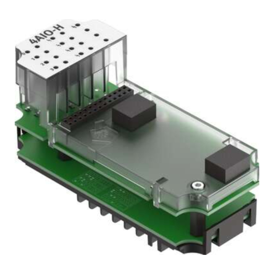
Page 9: Structure Of Analogue Module
Housing bottom part for electrical and mechanical linkage of the CPX modules – Variant with connection possible for operating and load voltage – Mounting option for entire terminal CPX Tab. 5 Module components of analogue module Festo — CPX-4AE-4AA-H — 2019-04a... -
Page 10: Manifold Block
For round plug M12x1 and SPEEDCON M12 – Screening possible using metal thread CPX-P-AB-4XM12-4POL Terminal manifold block – 2 pin headers COMBICON, 8-pin – For terminal strips in spring-loaded and screw terminal tech- nology CPX-P-AB-2XKL-8POL Tab. 6 Manifold blocks Festo — CPX-4AE-4AA-H — 2019-04a... -
Page 11: Connection And Display Components
9 Display channel status (per channel 1 LED) / 4 Display channel error (LED red) LED 0…3 (green): input / LED 0…3 (yellow): 5 Electrical connections (here: M12) output Fig. 3 Connection and display components – example of M12 manifold block Festo — CPX-4AE-4AA-H — 2019-04a... -
Page 12: Product-Specific Terms And Abbreviations
Dismounting and remounting of the electronics module by setting the DIL switches or exchanging the electronics module Arrangement on terminal CPX For further information on the arrangement of the modules, observe the description of system CPX and the module documents è 2.1 Applicable documents. Festo — CPX-4AE-4AA-H — 2019-04a... -
Page 13: Mechanically Coding The Manifold Block
– The manifold block has a recess for a coding piece at the bottom. – Manifold block in pre-assembled CPX terminals are mechanically coded at the factory. Fig. 4 Coding pin on the electronics module Festo — CPX-4AE-4AA-H — 2019-04a... - Page 14 3. Align the plug of the manifold block with the plug of the electronics module. 4. Push the manifold block onto the electronics module without tilting until the coding piece in the manifold block engages. Festo — CPX-4AE-4AA-H — 2019-04a...
- Page 15 1. Lay the manifold block 4 on a flat surface, top side first. 2. Unlock and remove the cover 1. 3. Press out the coding piece 3 using a suitable tool 2. 4. Push the cover onto the plug of the manifold block 5. Festo — CPX-4AE-4AA-H — 2019-04a...
-
Page 16: Mounting The Electronics Module And Manifold Block
DIL switches are set è Tab. 8 DIL switch settings. 1 Manifold block 5 Interlinking block 2 Screws (TORX T10) 6 Coding pin 3 Electronics module 7 Plug 4 Contact rails Fig. 7 Mounting of the electronics module and manifold block – example Festo — CPX-4AE-4AA-H — 2019-04a... -
Page 17: Dismounting The Electronics Module And Manifold Block
Operating voltage for electronics and sensors – Load voltage of valves Power supply The operating and load voltage supply is fed through interlinking blocks or end plates (Protective Extra-Low Voltage, PELV) è Description of system CPX. Festo — CPX-4AE-4AA-H — 2019-04a... -
Page 18: Changing The Configuration Of The Analogue Current Channels (Dil Switches)
Channel 1: output Channel 2: output Channel 3: output 4AA-H 0 bytes 8 bytes Channel 0: output Channel 1: output Channel 2: output Channel 3: output – – – Reserved for test mode With HART variables Festo — CPX-4AE-4AA-H — 2019-04a... - Page 19 Channel 0: input Channel 1: output Channel 2: output Channel 3: output 4AA-H + 4HV 16 bytes 8 bytes Channel 0: output Channel 1: output Channel 2: output Channel 3: output Tab. 8 DIL switch settings Festo — CPX-4AE-4AA-H — 2019-04a...
-
Page 20: Electrical
Notes on the cable connection – For the connection of HART field devices: observe the wiring requirements according to the HART specification. – Observe the maximum line lengths for the connection of field devices: 500 m. Festo — CPX-4AE-4AA-H — 2019-04a... -
Page 21: Attaching Connecting Cables To The Manifold Block M12
The metal thread of socket contact M12 is internally connected to the earth terminal of terminal CPX and can be used as a screen connection. – Only use suitable plugs è www.festo.com/catalogue. – Seal unused connections with protective caps ISK-M12 è Accessories. Festo — CPX-4AE-4AA-H — 2019-04a... -
Page 22: Attaching Connecting Cables To The Terminal Manifold Block
/ IO AOUT X2.6 XGND X2.7 X2.8 XGND Tab. 10 Pin allocation on manifold block CPX-P-AB-2XKL-8POL These manifold blocks CPX-P-AB-2XKL-8POL have no connection for the cable screening. • Set up the screening or equipotential bonding separately. Festo — CPX-4AE-4AA-H — 2019-04a... - Page 23 Strip length [mm] Tab. 11 Specifications for spring-loaded terminal – Only use suitable terminal strips è www.festo.com/catalogue. – Connect only one conductor per spring-loaded terminal. – With a screwdriver, press the unlocking pin and insert the conductor end with the wire end sleeve into the terminal opening to the limit stop.
- Page 24 Strip length [mm] Tab. 12 Specifications for screw terminal – Only use suitable terminal strips è www.festo.com/catalogue. – Connect only one conductor per screw terminal. – Loosen the screw terminal, insert the conductor end with wire end sleeve and tighten the screw terminal (tightening torque: 0.5 … 0.6 Nm).
-
Page 25: Mechanically Coding The Terminal Connection
Installation 8.4.4 Mechanically coding the terminal connection The terminal connection can be mechanically coded with a coding system. The coding system is optionally available è www.festo.com/catalogue. – Recommendation: provide each contact with a coding element. 1 Terminal strip 3 Coding tab for the recess on the... -
Page 26: 3-Wire Connection Of Passive Hart Transmitters
4-wire connection of active HART transmitters 1 HART input module: passive 3 Auxiliary energy 2 HART transmitter: active Fig. 14 4-wire connection of an active HART transmitter Power supply for the HART transmitter via the auxiliary energy Festo — CPX-4AE-4AA-H — 2019-04a... -
Page 27: 2-Wire Connection Of Passive Hart Actuators
The analogue module is completely installed into terminal CPX and connected. Process image and address space allocation For each terminal CPX, 64 bytes are available for the cyclic data exchange of the inputs and outputs. Festo — CPX-4AE-4AA-H — 2019-04a... - Page 28 – – – Output 2 bytes – 2AE2AA-H Input 20 bytes + 4HV – – – – – Output 4 bytes – 1AE3AA-H Input 18 bytes + 4HV – – – – Output 6 bytes Festo — CPX-4AE-4AA-H — 2019-04a...
-
Page 29: Hart Variables
Determination of the HART variables to be transferred during parameterisation è 9.4 Parameterisation. Parameterisation The terminal CPX and the module described here can be parameterised with the operator unit (CPX- MMI), the Festo Maintenance Tool (CPX-FMT) software or the higher-level system. Festo — CPX-4AE-4AA-H — 2019-04a... -
Page 30: Recommended Parameterisation Sequence
Behaviour after short circuit/over- Automatic Tab. 17 load return – 1 7 Reserved … – – 4828 + m* 64 + 2 0 7 Reserved … – – 4828 + m* 64 + 3 0 7 Reserved … Festo — CPX-4AE-4AA-H — 2019-04a... - Page 31 Fail safe Channel 0 3 Tab. 31 … tions – Idle mode Channel 0 3 Tab. 32 … – Force channel 0 3 Tab. 33 … Tab. 15 Overview of the module and channel parameters Festo — CPX-4AE-4AA-H — 2019-04a...
-
Page 32: Description Of The Module And Channel Parameters
Bit 0: behaviour after short circuit/overload – Bit 1 7: reserved … Values – Bit 0: – 0 = leave voltage deactivated For voltage recovery, “Power On” or a re-parameterisation of the mod- ule parameter is required. Festo — CPX-4AE-4AA-H — 2019-04a... - Page 33 0 = Sign + 15 bit (default) – 1 = linear scaling – Bit 4: – 0 = inactive (default) – 1 = active Tab. 18 Description of the “Data format, monitoring according to NAMUR NE43” module parameter Festo — CPX-4AE-4AA-H — 2019-04a...
- Page 34 – Bit 1: monitoring of upper critical limit – Bit 2: monitoring of wire break (idling) – Bit 3: monitoring of overflow/underflow – Bit 4 6: reserved … – Bit 7: monitoring of parameterisation errors Festo — CPX-4AE-4AA-H — 2019-04a...
- Page 35 Bit 0 7: Low byte or high byte as critical limit … Values Default: -27648 (low byte = 0, high byte = 148) Tab. 20 Description of “Lower critical limit of channel 0 … 3" Festo — CPX-4AE-4AA-H — 2019-04a...
- Page 36 Bit 0 7: Low byte or high byte as critical limit … Values Default: 27648 (low byte = 0, high byte = 108) Tab. 21 Description of “Upper critical limit of channel 0 … 3" Festo — CPX-4AE-4AA-H — 2019-04a...
- Page 37 (0 10). … Allocation Bit 0 3: number of repetitions … Values Default: 0 Value range: 0 10 … Recommended setting: 5 Tab. 22 Description of the “HART repetition” module parameter Festo — CPX-4AE-4AA-H — 2019-04a...
- Page 38 LED light up red 7 Lower critical limit 3 Actual value 8 Actual value too low: channel error LED and 4 Error message on module error LED light up red. Fig. 17 Error messages at hysteresis Festo — CPX-4AE-4AA-H — 2019-04a...
- Page 39 4 20 mA without HART … 4 20 mA with HART … 0 20 mA … Channel 2 Inactive 4 20 mA without HART … 4 20 mA with HART … 0 20 mA … Festo — CPX-4AE-4AA-H — 2019-04a...
- Page 40 Allocation and values 4828 + m* 64 + 31 (m = module number) Channel Signal range Channel 0 Inactive Smoothing over 2 values Smoothing over 4 values Smoothing over 8 values Channel 1 Inactive Smoothing over 2 values Smoothing over 4 values Smoothing over 8 values Festo — CPX-4AE-4AA-H — 2019-04a...
- Page 41 Tab. 29 Allocation and values of “IEEE variable of HART variable 1, HART è variable 2” channel parameter, Tab. 30 Allocation and values of “IEEE variable of HART variable 3, HART è variable 4” channel parameter. Tab. 28 Description of “IEEE variable of channel 0 … 3" Festo — CPX-4AE-4AA-H — 2019-04a...
- Page 42 Source of HART variable 3 = QV Channel of HART variable 3 = channel 0 (default) Channel of HART variable 3 = channel 1 Channel of HART variable 3 = channel 2 Channel of HART variable 3 = channel 3 Festo — CPX-4AE-4AA-H — 2019-04a...
- Page 43 – 1 = Fault State (default) – Fault State channel 0 3: … – 0 = reset value (default) – 1 = set value Tab. 31 Description of "Fail-Safe channel 0 … 3" module parameter Festo — CPX-4AE-4AA-H — 2019-04a...
- Page 44 – 1 = Fault State (default) – Idle State channel 0 3: … – 0 = reset value (default) – 1 = set value Tab. 32 Description of "Idle-Mode channel 0 … 3" module parameter Festo — CPX-4AE-4AA-H — 2019-04a...
-
Page 45: Data Format And Range Of Values Of The Actual Values
D13 D12 D11 D10 D9 D8 D7 D6 D5 D4 D3 D2 D1 D0 field Value Digital input value 1) VZ = sign (0 = positive, 1 = negative) Tab. 34 Data format of the module CPX-4AE-4AA-H – Value range -32768 … 0 … 32767 Festo — CPX-4AE-4AA-H — 2019-04a... -
Page 46: Input 4
Actual value Digital input value Meaning 4 20 mA -32768 32767 Nominal range, freely scalable … … 1.19 mA -32768 Underflow < Tab. 36 Range of values for scalable data format (input 4 … 20 mA) Festo — CPX-4AE-4AA-H — 2019-04a... -
Page 47: Input 0
20 mA -32768 32767 Nominal range, freely scalable … … 0 mA -32768 Underflow not possible: < < Reverse polarity protection Tab. 38 Range of values for scalable data format (input 0 … 20 mA) Festo — CPX-4AE-4AA-H — 2019-04a... -
Page 48: Output 4
22 mA Overflow > -32768 0 32767 4 20 mA Nominal range, freely scalable … … … -32768 0 mA Underflow < Tab. 40 Range of values for scalable data format (output 4 … 20 mA) Festo — CPX-4AE-4AA-H — 2019-04a... -
Page 49: Output 0
22 mA Overflow > -32768 0 32767 0 20 mA Nominal range, freely scalable … … … -32768 0 mA Underflow < Tab. 42 Range of values for scalable data format (output 0 … 20 mA) Festo — CPX-4AE-4AA-H — 2019-04a... -
Page 50: Scaling The Range Of Values
The representation of errors in the bus nodes depends on the bus protocol è Description of bus nodes. A further possibility for diagnostics is the operator unit CPX-MMI. The operator unit displays the error messages in clear text è Description of operator unit CPX-MMI. Festo — CPX-4AE-4AA-H — 2019-04a... -
Page 51: Error Messages
0 … 3". Error in parameterisation – Re-parameterise with valid paramet- – Parameterisation is implausible. – The previous parameter setting of the 9.5 Data format and range of è channel is kept. values of the actual values. Festo — CPX-4AE-4AA-H — 2019-04a... - Page 52 1) The module displays the error depending on the parameterisation. The digital input values are processed again. 2) The diagnostics are output with the first recorded input value and kept until valid input values have been recorded for at least 200 ms. Tab. 44 Error messages of the analogue module Festo — CPX-4AE-4AA-H — 2019-04a...
-
Page 53: Led Display
All channel-specific errors Illu- – Parameterisation errors of hysteresis Tab. 17 Description of the “Behaviour after short circuit/overload” module parameter min- è ated – The DIL switch is incorrectly set. Tab. 45 LED display of module error Festo — CPX-4AE-4AA-H — 2019-04a... - Page 54 Channel active as input: – Signal range 4 20 mA with HART … – HART communication error-free Flash- Channel active as input Illu- min- ated Tab. 47 Display of status LED for channel status of input Festo — CPX-4AE-4AA-H — 2019-04a...
-
Page 55: Technical Data
… Flash- – HART communication error-free Channel active as output Illu- min- ated Tab. 48 Display of status LED for channel status of output Technical data Technical data of terminal CPX è Description of system CPX. Festo — CPX-4AE-4AA-H — 2019-04a... - Page 56 In accordance with EU Explosion Protection Dir- (declaration of conformity ective (ATEX) www.festo.com/sp.) In accordance with EU EMC Directive è Information on materials RoHS-compliant Information on materials – Housing PA-reinforced Tab. 49 General technical data Festo — CPX-4AE-4AA-H — 2019-04a...
- Page 57 Min. 20.7 at 20 mA Sensor cable length Max. 500 (screened) Electrical isolation between channels Electrical isolation between channel and internal bus Fuse protection (short circuit) Per channel Analogue outputs Load resistance [Ω] Max. 750 Tab. 50 Electrical data Festo — CPX-4AE-4AA-H — 2019-04a...
- Page 58 Copyright: Festo SE & Co. KG Ruiter Straße 82 73734 Esslingen Germany Phone: +49 711 347-0 Fax: +49 711 347-2144 Reproduction, distribution or sale of this document or communic- e-mail: ation of its contents to others without express authorization is service_international@festo.com...
Need help?
Do you have a question about the CPX-4AE-4AA-H and is the answer not in the manual?
Questions and answers