Table of Contents
Advertisement
Gechter GmbH Werkzeug- und Maschinenbau
Translation of the original operating manual
English
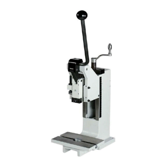
Hand toggle presses HKPE, HKPV and HKP
2,5 HKPE; 2,5 HKPV
5 HKPE; 5 HKPV
Type:
8/12 HKPV; 8/16 HKPV; 50 HKP
Representation of HKPV
The operating manual must be read prior to the initial commissioning!
Observe the safety instructions!
Keep for future use!
This documentation is not subject to any change service!
–
January
2016
Version: 00
December- 2020
Version: 01
Advertisement
Table of Contents


Need help?
Do you have a question about the HKPE Series and is the answer not in the manual?
Questions and answers