Dantherm RCV 320 P2 Basic Manual
Hide thumbs
Also See for RCV 320 P2 Basic:
- User and service manual (68 pages) ,
- User & service manual (496 pages)
Table of Contents
Advertisement
Quick Links
Advertisement
Table of Contents

Subscribe to Our Youtube Channel
Related Manuals for Dantherm RCV 320 P2 Basic


Summary of Contents for Dantherm RCV 320 P2 Basic
- Page 1 MANUAL RCV 320 P2 Basic Rev. 1.0 • 2021-W50-2...
-
Page 3: Table Of Contents
Table of contents This manual covers the following topics: Introduction . . . . . . . . . . . . . . . . . . . . . . . . . . . . . . . . . . . . . . . . . . . . . . . . . . . . . . . . . . . . . . . . . . . . .4 About this Manual. -
Page 4: Introduction
Copying this service manual, or parts thereof, is not permitted without the prior written con- Copyright sent of Dantherm. Dantherm reserves the right to change and improve the product and service manual at any Reservations time without prior notice or obligation. - Page 5 Introduction: About this Manual The following symbols are used in this manual to draw attention to hazards and additional Symbols in this information of particular relevance. manual Category Symbols Used Risks/ meaning Risk of serious injury. Warning WARNING General warning symbols Risk of minor or moderate injury or damage to Caution...
-
Page 6: User Manual
It is important to know the correct operating procedure for the residential ventilation system tions and all its safety measures. Dantherm accepts no liability with regard to lost business or per- sonal injury as a result of non-compliance with safety measures. -
Page 7: Operation
USER MANUAL Operation: Control panel - overview Operation Control panel - overview interface The control panel has four buttons (two on the left side and two on the right side) with corre- sponding LEDs underneath. An LED light with four levels indicating the fan speed is situated in the middle. -
Page 8: Main Operating Modes
You can activate the week program via the control panel on the unit, but you cannot choose which week program you want to run. Selection between the 11 weekly programs (10 set programs + one adjustable in PC Tool) can only be done using the Dantherm app, the HRC3 remote control or a PC Tool. -
Page 9: Temporary Modes (Override)
You can change the setpoints for min. outdoor temperature (Tmin) (default setting: 15°C) and max. indoor temperature (Tmax) (default setting: 24°C) via PC Tool or the Dantherm HRC3 remote control. If the conditions for automatic bypass are present, an open damper is indicated... - Page 10 USER MANUAL Operation: Temporary modes (override) Summer mode When summer mode is active, this will stop the supply air fan and only the extract air fan will be in operation. In this case, a fresh air supply can be ensured by opening windows, doors, etc.
-
Page 11: Maintenance And Care
USER MANUAL Maintenance and care: Inspection of the filter Maintenance and care Inspection of the filter Introduction Preventive maintenance is necessary at regular intervals if the unit is to operate efficiently and optimally without unintended stoppages, and to ensure the expected service life of at least 10 years. - Page 12 USER MANUAL Maintenance and care: Inspection of the filter When the filters have been replaced, the filter alarm must be reset by pressing the alarm button for 5 seconds. A short beep will sound, indicating that the filter alarm has been reset correctly.
-
Page 13: Installation & Service Manual For Professionals
It is important to know the correct operating procedure for the residential ventilation system and all its safety measures. Dantherm accepts no liability with regard to lost business or per- sonal injury as a result of non-compliance with safety measures. -
Page 14: Transport And Unpacking
INSTALLATION & SERVICE MANUAL FOR PROFESSIONALS Transport and unpacking: Unpacking Transport and unpacking Unpacking Check for Step Action transport damage Report any obvious damage to the carrier, packing company, postal service, etc. immediately after delivery, and note the damage in the consignment or transport documents. -
Page 15: Declaration Of Conformity
INSTALLATION & SERVICE MANUAL FOR PROFESSIONALS Transport and unpacking: Declaration of Conformity Declaration of Conformity Dantherm hereby declares that the unit mentioned below: No.: 352482 Type: RCV 320 – complies with the following directives: 2014/35/EU Low Voltage Directive 2014/30/EU EMC Directive... -
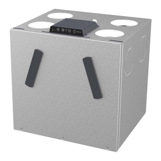
Page 16: Product Description
General description Introduction The RCV product range from Dantherm is a residential ventilation system designed to supply homes with fresh and filtered air, and where the heat in the extract air is transferred to the supply air without mixing the two airflows. This results in energy-efficient ventilation with low heat energy loss. - Page 17 INSTALLATION & SERVICE MANUAL FOR PROFESSIONALS Product description: General description Airflow direction This section shows the possibilities of the air flow through the unit according to operation in mode A/B mode A and B. The default operation mode is mode A (see how to change to mode B on page 29). Mode A Fig.
- Page 18 INSTALLATION & SERVICE MANUAL FOR PROFESSIONALS Product description: General description Description of This illustration shows the function of the different parts in mode A/B, including the filter, fan parts in mode A/B and use of drain outlet. Filter 1 Filter 2 Fan box 2 Fan box 1 Fig.
-
Page 19: Component Descriptions
INSTALLATION & SERVICE MANUAL FOR PROFESSIONALS Product description: Component descriptions Component descriptions Introduction This section describes the individual components of the RCV units included in the standard delivery. Cabinet The external parts of the cabinet are made of aluzink sheet metal. The internal parts of the cabinet are made of polystyrene (EPS). - Page 20 INSTALLATION & SERVICE MANUAL FOR PROFESSIONALS Product description: Component descriptions Illustration of This illustration shows the RCV units' control section. control parts Fig. 7 Loc . Mode A Mode B T1 temperature sensor - outdoor air T3 temperature sensor - extract air T2 temperature sensor - supply air T4 temperature sensor - exhaust air T3 temperature sensor - extract air...
-
Page 21: Accessories
INSTALLATION & SERVICE MANUAL FOR PROFESSIONALS Product description: Accessories Accessories Introduction The unit is supplied without mounted accessories. If additional functionality is requested, the accessories must be installed prior to the first installation of the unit or, alternatively, after commissioning. Electrical pre- The unit can be equipped with an electrical preheating element that preheats the incoming heating... - Page 22 INSTALLATION & SERVICE MANUAL FOR PROFESSIONALS Product description: Accessories VOC, humidity and The unit can be equipped with a VOC (air sensor quality), humidity or CO sensor. Mounted sensors will continuously monitor the extract air and adjust the airflow accordingly. This mode of operation is called demand- controlled mode.
-
Page 23: Electronic Control
Ethernet router with DHCP Extract air fan system Supply air fan HAC2 FPC (accessory) Dantherm Main controller PCB Air quality demand sensor (VOC) HCP 11 on MODBUS Humidity (wired remote control) demand sensor (RH %) 2 digital inputs... - Page 24 INSTALLATION & SERVICE MANUAL FOR PROFESSIONALS Product description: Electronic control This illustration shows the main PCB and the control panel on the RCV 320. Illustration of unit's control area Fig. 9 Loc . Part USB connection for: • Use of PC Tool for calibration purposes, software update, change of settings, etc. •...
-
Page 25: Accessing The Main Pcb
INSTALLATION & SERVICE MANUAL FOR PROFESSIONALS Product description: Accessing the main PCB Accessing the main PCB Introduction Depending on the installation site and your preferences, you have three options of accessing the main PCB (see in this section). Injury caused by electric shock and risk of damage to the device WARNING •... - Page 26 INSTALLATION & SERVICE MANUAL FOR PROFESSIONALS Product description: Accessing the main PCB Access main PCB through the inside of the unit Option 3 Step Action Illustration Release the three screws from the front at the bottom of the unit and remove the front cover.
-
Page 27: Control System Strategy
INSTALLATION & SERVICE MANUAL FOR PROFESSIONALS Product description: Control system strategy Control system strategy Introduction This section describes the control system strategy under different conditions. Preheat If a preheater is installed, the unit can add electrical heating to T1 outdoor air to reduce de- frosting situations and increase the supply air temperature. - Page 28 INSTALLATION & SERVICE MANUAL FOR PROFESSIONALS Product description: Control system strategy 2 . Fireplace in house is the alternative defrosting strategy, that can be chosen via PC Tool. Alternative de- frosting strategy • Both the supply and exhaust air fan speed will slowly decrease until the minimum RPM is reached •...
-
Page 29: Installation Options
INSTALLATION & SERVICE MANUAL FOR PROFESSIONALS Installation Options: Switching between modes A and B Installation Options Switching between modes A and B Introduction The RCV 320 has the option of swapping the duct connections according to the description in section “Product description” -”General description”. This section will guide you through the process of switching from operating mode A to B. - Page 30 INSTALLATION & SERVICE MANUAL FOR PROFESSIONALS Installation Options: Switching between modes A and B Move the cable port, incl. hu- midity sensor (and VOC sensor, if present), to the sensor position for mode B. CAUTION Warning Insufficient device perfor- Caution mance and ventilation effect To ensure optimal device performance, all wired...
-
Page 31: Installation
INSTALLATION & SERVICE MANUAL FOR PROFESSIONALS Installation: Location Considerations Installation Location Considerations Warranty claims Use of an appliance outside the specified conditions and contrary to its intended use will re- sult in loss of all warranty claims. The warranty is limited to devices installed solely by trained and certified personnel. -
Page 32: Mounting The Device
INSTALLATION & SERVICE MANUAL FOR PROFESSIONALS Installation: Mounting the device Mounting the device Wall mounting Follow these steps when mounting the RCV 320 on the wall. Step Action Illustration Fix and level the 516 mm wall rail using 220 mm 42 mm these measure- ments. - Page 33 INSTALLATION & SERVICE MANUAL FOR PROFESSIONALS Installation: Mounting the device Make sure the unit is levelled or tilts backwards. CAUTION Warning If the unit tilts forwards, there Caution is a risk of water damage . • Make sure the unit is levelled or tilts back- wards.
- Page 34 Step Action Illustration Install the Dantherm approved floor brackets (accessory) on the RCV unit to ensure that the system is raised from the floor in a safe manner. Note: Dantherm accepts no liability to floor brackets from other suppliers. Use of other (non-Dantherm) constructions is at your own risk.
- Page 35 INSTALLATION & SERVICE MANUAL FOR PROFESSIONALS Installation: Mounting the device Drain/condensate The unit is equipped with a blanked-off drain. Connect the drain hose to the correct conden- drain sate outlet at the bottom of the unit. Step Action Illustration Check the ventilation system's mode (A/B) on the main PCB.
- Page 36 INSTALLATION & SERVICE MANUAL FOR PROFESSIONALS Installation: Mounting the device The siphon can be made in two ways: A) just below the unit (suitable for the majority of wall installations) or alternatively at the end of the drain hose (suitable for floor installations) Make also sure that you: •...
- Page 37 Make sure always to calculate how much insulation is needed in the current installa- tion. Contact your Dantherm distributor for further information. Dantherm accepts no liability to water damages caused by an inappropriate duct installation. Dust hazard...
-
Page 38: Calibration Of Airflow
INSTALLATION & SERVICE MANUAL FOR PROFESSIONALS Installation: Calibration of airflow Calibration of airflow Introduction In order to achieve the correct comfort level, as well as to control humidity levels, it is import- ant to adjust the amount of supply air entering the house, as well as the exhaust air from the house. -
Page 39: External Connections
With PC Tool it is possible to allocate a static IP address to the device. MODBUS MODBUS RTU is only for internal communication between the unit (main PCB) and Dantherm accessories (HAC, FPC, or HCP11). Modbus RTU connects via the RS485 port. -
Page 40: Maintenance And Care
INSTALLATION & SERVICE MANUAL FOR PROFESSIONALS Maintenance and care: Preventive maintenance Operation Operating the See user manual section ”Operation” on page 7. device Maintenance and care Preventive maintenance Introduction Preventive maintenance is necessary at regular intervals if the unit is to operate efficiently and optimally without unintended downtime and to ensure the expected service life of at least 10 years. - Page 41 INSTALLATION & SERVICE MANUAL FOR PROFESSIONALS Maintenance and care: Preventive maintenance Preparation for Remove the front cover for inspection. inspection Step Action Illustration Release the three screws from the front at the bottom of the unit and remove the front cover. The unit has a built-in filter alarm timer (every six months as standard).
- Page 42 INSTALLATION & SERVICE MANUAL FOR PROFESSIONALS Maintenance and care: Preventive maintenance Fans Step Action Illustration (2 years) WARNING There might be sharp edges on the fan boxes, which implies a risk of cutting yourself . • Wear protective gloves while inspecting and cleaning the fan boxes. Remove one of the fan boxes.
- Page 43 INSTALLATION & SERVICE MANUAL FOR PROFESSIONALS Maintenance and care: Preventive maintenance Heat exchanger Step Action Illustration (2 years) Remove the heat exchanger from the unit. Clean the heat exchanger with a soft brush and a vacuum cleaner at all four inlets. In special cases, for example, if there are clear traces of accumulated, dirty condensed water in the heat exchanger, it will be neces-...
-
Page 44: Troubleshooting
Introduction This section shows you how to recognize and understand possible operating errors. For correct fault tracing Dantherm strongly recommends connecting a remote control or PC with installed PC Tool or the Dantherm App, that works with the unit. Errors are displayed on the HRC3 remote control with "E” + a number. The issue can then be... -
Page 45: Error List
INSTALLATION & SERVICE MANUAL FOR PROFESSIONALS Maintenance and care: Error list Error list See the list below for a complete description: Error Action Error Possible cause Reset code required Filter alarm Filter period Dismount filters and Reset alarm and expired inspect for dirt reset filter by pressing and... - Page 46 INSTALLATION & SERVICE MANUAL FOR PROFESSIONALS Maintenance and care: Error list Error Action Error Possible cause Reset code required Bypass damper Selector switch Check if Bypass is Automatic reset does not close as enabled in PC Tool if efficiency is position A: expected high enough for...
- Page 47 INSTALLATION & SERVICE MANUAL FOR PROFESSIONALS Maintenance and care: Error list Error Action Error Possible cause Reset code required Extract air tem- Temperature Mount temperature Automatic reset perature sensor sensors are not sensors correctly if temperature (T1) mounted cor- is within normal rectly range for 30 seconds...
- Page 48 INSTALLATION & SERVICE MANUAL FOR PROFESSIONALS Maintenance and care: Error list Error Action Error Possible cause Reset code required 11 R E 11 Supply air tem- Low temperatures Ensure all ventilated Perform a perature < +5 °C pulled out of un- manual reset rooms are heated heated rooms...
- Page 49 INSTALLATION & SERVICE MANUAL FOR PROFESSIONALS Maintenance and care: Error list Error Action Error Possible cause Reset code required 13 - E 13 Communication Try again every error / poor signal 5 minutes or if a button is Shown only on pressed wireless remote control...
- Page 50 INSTALLATION & SERVICE MANUAL FOR PROFESSIONALS Maintenance and care: Error list Error Action Error Possible cause Reset code required 16 R Firmware 2.9 and Fire protection Check connection Perform a controller with to fire protection manual reset this address has controller by pressing the FPC fault (option)
-
Page 51: Spare Parts
INSTALLATION & SERVICE MANUAL FOR PROFESSIONALS Maintenance and care: Spare parts Spare parts Introduction Spare parts for the RCV 320 are available via the webshop: shop.dantherm.com. -
Page 52: Appendix
INSTALLATION & SERVICE MANUAL FOR PROFESSIONALS Appendix: Technical data Appendix Technical data Data sheet Specification Abbr . Unit RCV 320 P2 RCV 320 P2 Basic Max. flow at 100Pa m3/h 100Pa Max. rated flow at 100Pa m3/h max.nom Operating range DIBt m3/h... -
Page 53: Illustrations
INSTALLATION & SERVICE MANUAL FOR PROFESSIONALS Illustrations: Technical data Illustrations Illustration with This illustration shows the wiring diagram for the unit wiring diagram Fig. 12... -
Page 54: Cabinet Dimensions
Top view Bottom view Linear dimensions without tolerances according to Sheetmetal flatstate is based on Dantherm Air Handling A/S Surface appearance according to reference DS/ISO 2768-m. Angular dimensions without tolerances: ± 1° process equipment and is only intended as a guide. - Page 56 Denmark support.dantherm.com Dantherm can accept no responsibility for possible errors and changes (en) Dantherm kan inte ta något ansvar för eventuella fel och förändringar (se) Der tages forbehold for trykfejl og ændringer Irrtümer und Änderungen vorbehalten Dantherm n’assume aucune responsabilité pour erreurs et modifications éventuelles...
Need help?
Do you have a question about the RCV 320 P2 Basic and is the answer not in the manual?
Questions and answers