
Related Manuals for Dantherm RCV320 P1


Summary of Contents for Dantherm RCV320 P1
- Page 1 Original user and service instructions RCV320 P1/RCV320 P2 | en | *110956* 110956 Rev. 1.2 · 2023-W19...
-
Page 3: Table Of Contents
USER MANUAL Table of contents Table of contents Introduction ................4 Overview . -
Page 4: Introduction
Copyright No part of this manual may be reproduced without the prior written permission of Dantherm. Recycling This unit is designed to provide a long service life. At the end of its service life, the unit must be recycled in accordance with national regulations and with high environmental protection considerations. - Page 5 Introduction: Overview The following abbreviations are used in this manual: Abbreviations in this manual Abbreviation Description Outside air inlet into the unit Supply air from the unit into the dwelling Extract air from the dwelling into the unit Extract air from the unit Temperature sensor no 1 Temperature sensor no 2 Temperature sensor no 3...
-
Page 6: Symbols Used In The Operating Instructions
Introduction: Symbols used in the operating instructions Symbols used in the operating instructions In these operating instructions, particularly important text passages are highlighted with signal words and symbols that are described below. Signal words DANGER ...indicates a hazard which, if not avoided, will result in death or serious injury. WARNING ...indicates a hazard which, if not avoided, could result in death or serious injury. -
Page 7: User Manual
USER MANUAL Overview: Introduction USER MANUAL Overview Introduction Target group This part of the manual is intended for the users of the product. All instructions described in the Installation and Service Manual for Professionals must be carried out by trained technicians. Note! Read carefully before use. -
Page 8: Operation
USER MANUAL Operation: Overview Operation Overview DANGER Danger to life due to exhaust gases! When using open fireplaces in combination with this unit, negative pressure may arise inside the dwelling. The exhaust gases produced at the fireplace will be carried into the dwelling and can endanger your life. -
Page 9: Standard Operating Modes
Selecting one of the 11 week programs (10 preset programs + one customisable program in the PC tool) can only be achieved via the Dantherm app, the HRC3 remote control or the PC tool. For more information on the weekly programmes, please refer to the chapter "Week programs of the time switch". - Page 10 USER MANUAL Operation: Standard operating modes Demand- Activate demand-controlled operation if you want to control the quality of the room air automatically. In this mode, the measured values of the VOC, RH and/or CO sensors are used controlled to control the quality of the room air. Therefore, the respective sensors must be connected for operation demand-controlled operation.
-
Page 11: Temporary Operating Modes (Override)
You can change the setpoints for the minimum outdoor temperature (Tmin, default setting: 15 °C) and max. indoor temperature (Tmax, default setting: 24 °C) via the PC tool or the Dantherm HRC3 remote control. If the conditions for automatic bypass are met, the open status of the damper is indicated by the continuous illumination of the corresponding LED. - Page 12 USER MANUAL Operation: Temporary operating modes (override) Summer mode In summer mode, the supply air fan is stopped so that only the extract air fan is operating. In this case, the fresh air supply is ensured by opening windows, doors, etc. INFORMATION The summer mode is automatically deactivated once the outdoor temperature drops below 14 °C.
-
Page 13: Week Programs Of The Time Switch
USER MANUAL Operation: Week programs of the time switch Week programs of the time switch The following illustrations indicate the preset fan stages for one day (0 to 24 h) in the respective programs. Each of the programs offers two settings: • Weekdays (Mon–Fri) •... - Page 14 USER MANUAL Operation: Week programs of the time switch Program 6 2 2 2 2 2 2 2 2 2 2 2 2 2 2 Weekdays 1 1 1 1 1 1 1 1 2 2 2 2 2 2 2 2 2 2 2 Weekend 1 1 1 1 1 1 1 1 1 1 1 1 1...
-
Page 15: Maintenance And Care
USER MANUAL Maintenance and care: Maintenance and care Preventive maintenance activities are required at regular intervals to ensure efficient and optimal operation without unwanted failure and to ensure an expected service life of at least 10 years. Note that the filter maintenance intervals may vary depending on the specific ambient conditions. - Page 16 USER MANUAL Maintenance and care: 4. Insert the clean filters into the unit. Ensure that the filters are inserted the right way round. The arrows on the filter must point in the direction shown here. Fig. 3: Checking the filter for correct installation direction 5.
-
Page 17: Installation And Service Manual For Professionals
Safety precautions It is essential to be familiar with the correct operating procedure of the residential ventilation system and all safety measures. Dantherm accepts no liability for operational failures or personal injury resulting from the failure to comply with safety measures. -
Page 18: Product Description
INSTALLATION AND SERVICE MANUAL FOR PROFESSIONALS Product description: Scope of delivery and unpacking Product description Scope of delivery and unpacking Check the scope of delivery for transport damage during unpacking: 1. Report obvious, external damages to the carrier, packaging company, post office, etc. immediately upon receipt and note the damage in the consignment or transport documents. -
Page 19: General Description
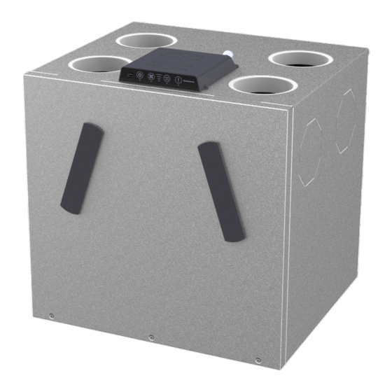
INSTALLATION AND SERVICE MANUAL FOR PROFESSIONALS Product description: General description General description The residential ventilation unit RCV320 is designed to supply dwellings with fresh and Introduction filtered air. The heat from the extract air is transferred to the supply air inside the unit without mixing the two airflows. - Page 20 INSTALLATION AND SERVICE MANUAL FOR PROFESSIONALS Product description: General description Airflows The unit offers the possibility to swap the directions of the airflows so that there are two operating modes: • Mode A • Mode B The inputs and outputs of the airflows in the two operating modes are depicted in the following figures: By default, the ducts on the side and bottom of the unit are closed but can be opened and used as shown below.
- Page 21 INSTALLATION AND SERVICE MANUAL FOR PROFESSIONALS Product description: General description This illustration shows the function of the different parts in mode A/B, including the filter, Filters and fans in the fan and the use of the condensate drain. mode A/B Fig. 11: Parts in mode A/B Item Mode A Mode B...
- Page 22 INSTALLATION AND SERVICE MANUAL FOR PROFESSIONALS Product description: General description Sensors in A/B This illustration shows the function of the sensors in mode A/B. mode Fig. 12: Positioning of the sensors Item Locati Mode A Mode B T1 temperature sensor – outside air T3 temperature sensor – extract air T2 temperature sensor –...
-
Page 23: Components Description
INSTALLATION AND SERVICE MANUAL FOR PROFESSIONALS Product description: Components description Components description The individual components of the units included in the standard scope of delivery are described in this section. Cabinet The outer parts of the cabinet are made of aluzinc sheet metal. To add accessories or replace components, the front cover must be removed. -
Page 24: Accessories
INSTALLATION AND SERVICE MANUAL FOR PROFESSIONALS Product description: Accessories Accessories The unit is delivered ex-factory without any optional accessories mounted. The accessories are to be mounted prior to initial unit installation, or, if required, after start-up, if additional functionality is requested. For the installation of the accessories, please refer to the instructions supplied with each accessory. - Page 25 INSTALLATION AND SERVICE MANUAL FOR PROFESSIONALS Product description: Accessories A wired remote control HCP 11 (without display) can be connected to the unit if the control Wired remote unit is difficult to reach due to the location of the unit. The remote control provides the control (HCP 11) same functions as the control unit.
- Page 26 INSTALLATION AND SERVICE MANUAL FOR PROFESSIONALS Product description: Accessories Filter Replacement filters in sets of 2 ISO Coarse filters or 1 ISO Coarse filter plus 1 ePM1 filter (pollen filter) are available as spare parts. Adapter set for Use the adapter for the openings on the bottom side of the unit. The lip seals on the adapter ensure an airtight connection between the unit and the connected ducts.
-
Page 27: Special Operating Modes
INSTALLATION AND SERVICE MANUAL FOR PROFESSIONALS Product description: Special operating modes Special operating modes In this section, the operation of the system under special conditions is described. For details on the standard operating modes, please refer to page 9. Preheating (with If a preheating coil is installed, the unit can additionally heat the outdoor air (T1) electrically to reduce the risk of frost and increase the supply air temperature. - Page 28 INSTALLATION AND SERVICE MANUAL FOR PROFESSIONALS Product description: Special operating modes Alternative If there is a fireplace in the house, the alternative defrosting procedure is selected via the PC tool and will trigger the following steps: defrosting procedure • The speed of the supply air fan and exhaust air fan decreases slowly until the minimum speed is reached.
-
Page 29: Description Of The Components Of The Control Unit
Smart- sensors T1–T4 phone Ethernet router with DHCP Exhaust air fan Supply air fan HAC2 FPC (accessories) Dantherm main PCB Air quality sensor (VOC) HCP 11 on MODBUS (wired remote control) Humidity sensor (RH %) 2 digital inputs High/low fan speed, etc. - Page 30 Dig In: Modbus: External digital input to select specific The Modbus RTU port is intended for in- operations ternal communication between the unit and Dantherm accessories (HAC2 + Antenna: HCP 11 + FPC) Antenna slot for connection to the radio remote control Ethernet:...
- Page 31 MODBUS RTU is used for internal communication between the unit (main PCB) and MODBUS Dantherm accessories (HAC, FPC or HCP11). Modbus RTU is connected via the RS485 port. INFORMATION An external Building Management System (BMS) cannot be connected as Modbus RTU via the RS485 connection or via Dantherm accessories (HAC, FPC, or HCP11).
- Page 32 INSTALLATION AND SERVICE MANUAL FOR PROFESSIONALS Product description: Description of the components of the control unit Connecting to Connect the unit to a LAN port using a standard Ethernet cable with an RJ45 connector. If a non-prefabricated cable is used, first install a sufficient cable length through the house. Mount the RJ45 connector using the standard Ethernet cable crossover terminology as specified in T568B.
-
Page 33: Installation
INSTALLATION AND SERVICE MANUAL FOR PROFESSIONALS Installation: General requirements Installation General requirements Using a unit outside the specified conditions and contrary to the intended use leads to the Warranty claims loss of all warranty claims. The warranty is limited to units that have been installed exclusively by trained and certified personnel. -
Page 34: Access To The Main Pcb
INSTALLATION AND SERVICE MANUAL FOR PROFESSIONALS Installation: Access to the main PCB Access to the main PCB DANGER Risk of electric shock! You can be severely injured by an electric shock. • Always disconnect the unit from the mains by removing the mains plug from the socket before opening the unit! There are three different ways to access the main PCB: •... - Page 35 INSTALLATION AND SERVICE MANUAL FOR PROFESSIONALS Installation: Access to the main PCB 2. Turn the cabinet over to gain access to the main PCB. Fig. 27: Turning the control unit 1. Loosen the three screws on the bottom of the unit and remove the front cover. Option 3 Fig. 28: Removing the front cover 1.
-
Page 36: Installation Options
INSTALLATION AND SERVICE MANUAL FOR PROFESSIONALS Installation: Installation options Installation options Change-over to operating mode B DANGER Risk of electric shock! You can be severely injured by an electric shock. • Always disconnect the unit from the mains by removing the mains plug from the socket before opening the unit! The unit offers the option to exchange the duct connections as described in the section "Product description –... - Page 37 INSTALLATION AND SERVICE MANUAL FOR PROFESSIONALS Installation: Installation options 4. Move the cable gland incl. humidity sensor (and VOC sensor, if available) to the position for operating mode B and insert the empty cable gland from position B to position A. Note that 50 mm distance are required from the sensor head to the cable gland in order to obtain a correct measurement.
- Page 38 INSTALLATION AND SERVICE MANUAL FOR PROFESSIONALS Installation: Installation options Using the side or INFORMATION bottom connections You can use two duct connections at a time. If you only want to use the duct connections on the side or at the bottom, you have to close the corresponding duct connections at the top. CAUTION Risk of hand injuries! You may cut yourself on sharp edges when cutting out the metal parts.
- Page 39 INSTALLATION AND SERVICE MANUAL FOR PROFESSIONALS Installation: Installation options 3. If you will not be using the air duct connections on the top, place an insulation piece in a cap. Then close the corresponding duct connection on the top of the unit with the insulation cap.
-
Page 40: Assembly
INSTALLATION AND SERVICE MANUAL FOR PROFESSIONALS Installation: Assembly Assembly Wall mounting 1. Fix and level the wall rail with the dimensions shown. Note: Make sure to use suitable screws and wall plugs. 516 mm 220 mm 42 mm 600 mm Fig. 39: Mounting the wall rail 2. - Page 41 100 mm Fig. 43: Creating a wooden substructure 2. Fit the Dantherm-approved floor brackets (accessories) to the unit to establish the required distance from the unit to the floor. Information: Dantherm accepts no liability for floor brackets from other manufacturers. Using other floor mounts is at your own...
- Page 42 INSTALLATION AND SERVICE MANUAL FOR PROFESSIONALS Installation: Assembly 3. Set up the unit and ensure that it is aligned horizontally. Note: The top edge must not be inclined backwards as this may cause moisture damages. Fig. 44: Setting up the unit horizontally When the unit is delivered, the condensate drains are closed.
- Page 43 INSTALLATION AND SERVICE MANUAL FOR PROFESSIONALS Installation: Assembly 2. Check to which drain (A/B) the condensate drain must be connected. The process is depicted in the following figures. Fig. 46: Condensate drain for operating mode A and B Condensate drain for operating Condensate drain for operating mode B mode A...
- Page 44 INSTALLATION AND SERVICE MANUAL FOR PROFESSIONALS Installation: Assembly 5. Route the condensate drain hose in a way that a siphon is created that is at least 100 mm high. The siphon can be created in two ways: A) directly under the unit (suitable for most wall installations) or alternatively B) at the end of the drain hose (suitable for floor installations) Fig. 49: Creating a siphon 6.
- Page 45 INSTALLATION AND SERVICE MANUAL FOR PROFESSIONALS Installation: Assembly Connecting the air NOTICE ducts Danger from dust! Moisture, dirt or dust entering the duct system may damage the unit. • Protect ducts and connections until the house is cleaned and ready for occupancy. ü...
-
Page 46: Initial Start-Up And Calibration
INSTALLATION AND SERVICE MANUAL FOR PROFESSIONALS Installation: Initial start-up and calibration Initial start-up and calibration To control the humidity level and to achieve the right comfort level, it is important to regulate the amount of supply air entering the house and the amount of exhaust air being discharged from the house. - Page 47 INSTALLATION AND SERVICE MANUAL FOR PROFESSIONALS Installation: Initial start-up and calibration 5. Read out the pressure drop Δp inside the heat exchanger that is required for a desired volume flow from the airflow diagram. The pressure drop Δp is located on the unit (--- = supply air, - - = extract air).
- Page 48 INSTALLATION AND SERVICE MANUAL FOR PROFESSIONALS Installation: Initial start-up and calibration 10. Push the needles completely through the rubber cover of P1 and P2 (operation mode A, see figure) or P3 and P4 (operation mode B). Fig. 56: Calibrating the supply air, operating mode A 11.
-
Page 49: Maintenance And Troubleshooting
INSTALLATION AND SERVICE MANUAL FOR PROFESSIONALS Maintenance and troubleshooting: General maintenance instructions Maintenance and troubleshooting General maintenance instructions To ensure that the unit always meets the technical requirements, preventive maintenance activities have to be carried out at specified intervals. This can prevent breakdowns and inefficient operation and maximise the service life of the unit, i.e. -
Page 50: Cleaning The Interior Of The Unit
INSTALLATION AND SERVICE MANUAL FOR PROFESSIONALS Maintenance and troubleshooting: Cleaning the interior of the unit Cleaning the interior of the unit Every two years, the unit must be opened to check and clean some components. Loosen the three screws on the bottom of the unit and remove the front cover. Opening the unit Fig. 57: Removing the front cover Inspecting and... - Page 51 INSTALLATION AND SERVICE MANUAL FOR PROFESSIONALS Maintenance and troubleshooting: Cleaning the interior of the unit Check and clean the bypass with a brush if necessary. Inspecting and cleaning the bypass 1. Pull the heat exchanger out of the unit. Inspecting and cleaning the heat exchanger Fig. 59: Removing the heat exchanger...
-
Page 52: Troubleshooting
Maintenance and troubleshooting: Troubleshooting Troubleshooting In this section you will get to know how to detect and correct possible operating errors. Dantherm strongly recommends to connect a remote control to the unit for operation in order to perform proper troubleshooting. Error signals... - Page 53 INSTALLATION AND SERVICE MANUAL FOR PROFESSIONALS Maintenance and troubleshooting: Troubleshooting After any inspection or repair carried out due to potential errors, the unit can be reset by Resetting errors disconnecting the unit from the 230 V AC supply and then reconnecting it. This way, the control unit is reset.
- Page 54 INSTALLATION AND SERVICE MANUAL FOR PROFESSIONALS Maintenance and troubleshooting: Troubleshooting Error Fault Potential cause Action required Reset code Bypass damper Switch position A: Check whether bypass is ac- Automatic reset does not close as bypass is closed, but tivated in PC tool when efficiency is expected supply air temperat- high enough for...
- Page 55 INSTALLATION AND SERVICE MANUAL FOR PROFESSIONALS Maintenance and troubleshooting: Troubleshooting Error Fault Potential cause Action required Reset code Supply air temper- Temperature sensors Mount temperature Automatic reset if ature sensor (T2) are not mounted sensor(s) correctly the temperature is correctly within the normal Control board range for Resistance in one of...
- Page 56 INSTALLATION AND SERVICE MANUAL FOR PROFESSIONALS Maintenance and troubleshooting: Troubleshooting Error Fault Potential cause Action required Reset code 11 R Supply air temper- Low temperatures Ensure that all ventilated Manual reset by ature < +5 °C from unheated rooms are heated pressing the alarm rooms button on the Reduced heat re-...
- Page 57 INSTALLATION AND SERVICE MANUAL FOR PROFESSIONALS Maintenance and troubleshooting: Troubleshooting Error Fault Potential cause Action required Reset code 14 R Fire alarm Fire or smoke sensor Check for smoke or fire The alarm display Fire protection connected to this in- can be reset by Check if sensor and connec- thermostat connec- put is active...
-
Page 58: Annex
INSTALLATION AND SERVICE MANUAL FOR PROFESSIONALS Annex: Technical data Annex Technical data TECHNICAL DATA Abbr. Unit RCV 320 P1 RCV 320 P2 Max. flow rate at 100Pa 100Pa Max. nominal flow rate at 100Pa max.nom Operating range passive house VPHI 71 to 162 @ 100 Pa EN 13141-7 reference flow rate Vref... - Page 59 INSTALLATION AND SERVICE MANUAL FOR PROFESSIONALS Annex: Technical data TECHNICAL DATA Abbr. Unit RCV 320 P1 RCV 320 P2 ELECTRICAL SPECIFICATIONS Electrical voltage Max. Power consumption 170/1070 170/1370 (without/with preheater) Frequency Protection type (IP) * It is recommended to use a preheating coil at outdoor temperatures below -3 °C to ensure balanced ventilation.
-
Page 60: Cabinet Dimensions
Bottom view 463,5 Linear dimensions without tolerances according to Sheetmetal flatstate is based on Dantherm Air Handling A/S Surface appearance according to reference DS/ISO 2768-m. Angular dimensions without tolerances: ± 1° process equipment and is only intended as a guide. -
Page 61: Main Pcb With Connections
INSTALLATION AND SERVICE MANUAL FOR PROFESSIONALS Annex: Main PCB with connections Main PCB with connections Fig. 61: Main PCB with connections... -
Page 62: Spare Parts
INSTALLATION AND SERVICE MANUAL FOR PROFESSIONALS Annex: Spare parts Spare parts If spare parts are required, please visit Dantherm's online shop: shop.dantherm.com... -
Page 63: Declaration Of Conformity
INSTALLATION AND SERVICE MANUAL FOR PROFESSIONALS Annex: Declaration of conformity (EU) Declaration of conformity (EU) Dantherm A/S, Marienlystvej 65, DK – 7800 Skive, hereby declares that the unit mentioned below: no.: 352482 Type: RCV 320 (all variants included) – complies with the following directives:... - Page 64 INSTALLATION AND SERVICE MANUAL FOR PROFESSIONALS Annex: Declaration of conformity (UKCA) Declaration of conformity (UKCA) Dantherm, Marienlystvej 65, DK-7800 Skive, declares that the units mentioned below: Item no.: 352482 Type: RCV320 (all variants included) – confirm with the following directives: UK SI 2016 No. 1101 Electrical Equipment (Safety) Regulations 2016 UK SI 2016 No.
- Page 68 Marienlystvej 65 7800 Skive Denmark www.danthermgroup.com Dantherm can accept no responsibility for possible errors and changes (en) Der tages forbehold for trykfejl og ændringer (da) Irrtümer und Änderungen vorbehalten (de) Dantherm n’assume aucune responsabilité pour erreurs et modifications éventuelles (fr)
Need help?
Do you have a question about the RCV320 P1 and is the answer not in the manual?
Questions and answers