Table of Contents
Advertisement
Available languages
Available languages
Quick Links
Advertisement
Chapters
Table of Contents

Related Manuals for Dantherm HCV4


Summary of Contents for Dantherm HCV4
- Page 1 HCV 4 / HCV 5 User manual Rev. 1.2 EN•DA•DE•FR...
- Page 2 Der tages forbehold for trykfejl og ændringer Dantherm can accept no responsibility for possible errors and changes Irrtümer und Änderungen vorbehalten Dantherm n’assume aucune responsabilité pour erreurs et modifications éventuelles...
-
Page 3: Table Of Contents
Introduction Overview Introduction This is a user guide for the home ventilation units HCV 4/ HCV 5 from Dantherm A/S. The table of contents below provides an overview of the sections contained in the man- ual. Serial number For future inquiries concerning e.g. spare parts, please note the exact serial number of... -
Page 4: Introduction
Copying this user guide or parts thereof is not permitted without prior written permis- sion from Dantherm A/S. Reservations Dantherm A/S reserves the right at any time to carry out changes or improvements to the product and user guide without prior notification or obligation. Disposal The unit is designed to function for many years. - Page 5 General information, continued EU Declaration of Dantherm A/S, Marienlystvej 65, DK-7800 Skive declares at its own liability that the fol- Conformity lowing product: 352425 HCV 4 352422 HCV 5 covered by this declaration, complies with the following directives: 2014/35/EU LVC Directive (low voltage)
-
Page 6: Product Description
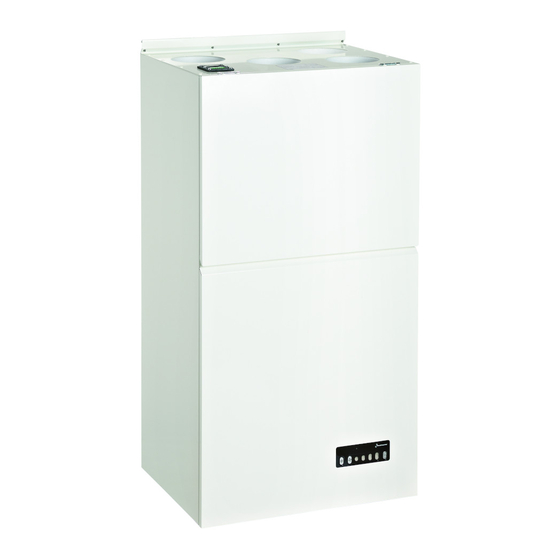
Product description Introduction This section provides a description of the unit. Use of the HCV The HCV unit is used to ventilate private homes. The unit supplies fresh, heated outside air through the unit to the home. Contaminated and hot exhaust air is used to heat the outside air through heat recovery. Illustration, inter- The illustration shows the different... - Page 7 Product description, continued Air flow The following describes and illustrates the air flow in an HCV 4: T4 T1 Description Outside air (T1) Outside air that enters the heat exchanger, ready to be heated by the exhaust air from the house (). ...
-
Page 8: Function Description
Function description Important The ventilation system must always be running! With the exception of the four hours during which the unit can be stopped from the control panel, stopping the unit is not recommended. Stopping the unit for longer peri- ods of time may result in the condensation of fresh air in the pipe installations and ven- tilation unit, which carries a risk of water damage in the building's construction, damage to the unit, and hygiene problems. - Page 9 Function description, continued Manual operation If a different volume of air is desired than what the unit provides automatically through its automatic demand control, the user can manually select from fan steps 0-4. See the following examples: Step Function On the control panel the unit can be set to four different speeds, fan step 1-4.
- Page 10 Function description, continued Manual bypass The purpose of the bypass function is to cool the home by allowing cool outside air directly into the home without heat recovery. During normal operation (when manual bypass is activated), the unit cools by using the automatic bypass control when outdoor and indoor temperatures allow, manual which is why, in most cases,...
-
Page 11: Description Of The Control Panel
Description of the control panel Introduction This section provides a detailed description of the HCP4 control panel. Illustration This illustration shows the control panel, which provides operating information via vari- ous indicators. The control panel has three buttons that are easy to activate: ... - Page 12 Description of the control panel, continued Part/function, contin- Part Function Upon activating the automatic demand control, the unit will operate based on the humidity of the home's exhaust air. Automatic demand control al- Automatic demand ways runs on fan step 1, 2 or 3. control In the event of a unit error, the control will beep ...
-
Page 13: Operation
Operation Introduction This section describes how the different functions are activated and operated. Additional information on the individual functions can be found in the “"Function de- scription” section at page 6, or in the "Set points" section in the installation guide. Power saving To save power, shut off all lights in the control panel after 2 minutes without operation (with the exception of the green LED). -
Page 14: Preventive Maintenance
Preventive maintenance Introduction In order for the unit to run reliably, it is necessary to perform preventive maintenance by changing the filter and cleaning the unit. Changing the filter Change the filter when the filter alarm is displayed in the control panel (the LED blinks yellow) and the acoustic filter alarm beeps (once an hour). - Page 15 Preventive maintenance, continued Cleaning Keep the unit clean to ensure reliable operation and proper hygiene. If the unit is dirty (for example around the filter openings), it must be cleaned using a thoroughly wrung-out cloth dipped in lukewarm water and, if necessary, detergent. Important: Chemical solvents must not be used! Guarantee condi- The factory guarantee is only valid with documented preventive maintenance.
-
Page 16: Optional Extras
This section provides an overview of the available optional extras for the HCV. There is a list of optional accessories accompanied by brief descriptions and item numbers for or- dering. Additional information on all accessories is available from Dantherm A/S; users can also visit www.dantherm-air-handling.com. Installation com-... - Page 17 Optional extras, continued Controls, continued Optional extras Illustration Description Product HAC 1 Box for connecting and controlling 063857 accessories such as: • Heating coils • Cooling coils • Duct damper • Stop function • Fire thermostat • CO sensor • Hygrostat •...
- Page 18 Optional extras, continued Heating coils, com- Optional extras Illustration Description Product plete Pre-/reheating- Pre-/reheating set, 900 W, 063898 set (electric) Ø 125 mm, 0-10 V-controlled. Must be connected to HAC 1 Pre-/reheating set, 1200 W, 063899 Ø 160 mm, 0-10 V-controlled. Must be connected to HAC 1 Pre-/reheating set, 1800 W, 063900...
-
Page 19: Fault Finding Guide
Fault finding guide Alarms Locate the problem in the left column, and follow instructions on the right: Alarm Cause Action Yellow LED (30/min) and Filters need to be re- Change filters and reset the beeping sound. placed/changed. filter timer on the unit. See "Preventive maintenance”, page 12. - Page 20 Fault finding guide, continued Problems, continued Problem Cause Action The unit does not The unit does not have a built- No error. cool sufficiently. in bypass module. Uneven operation, The unit has most likely been If this is the case, set the unit with a high degree set to automatic demand con- to manual operation and select...
- Page 21 Fault finding guide, continued Problems, Locate the problem in the left column, and follow instructions on the right: continued, continued Problem Cause The unit always runs at the The unit is set to manual Set the unit to automatic same speed. mode at a specific speed.
-
Page 22: Index
Index absence................. 7 holiday ..............6; 7 acoustic filter alarm ..........10; 12 HRC 2 ................14 adjusting set points ............ 14 humidity ..............10 air flow ................5 humidity sensor ............. 6 alarms ................. 14 hygiene ............... 13 arm, door ..............4 hygrostat .............. - Page 23 Introduktion Overblik Introduktion Dette er brugervejledningen for boligventilationsaggregaterne HCV 4/ HCV 5 fra Dantherm A/S. Indholdsfortegnelsen nedenfor giver et overblik over vejledningens afsnit. Serienummer For fremtidige henvendelser om fx reservedele beder vi dig notere det nøjagtige serie- nummer på aggregatet her: ______________________ Denne vejledning dækker aggregater med serienumre lig med eller højere end:...
- Page 24 Kopiering af brugervejledningen eller dele af den er ikke tilladt uden en skriftlig tilla- delse fra Dantherm A/S. Forbehold Dantherm A/S forbeholder sig retten til til hver en tid at foretage ændringer og forbed- ringer på produktet og i brugervejledningen uden forudgående meddelelse eller forplig- telser.
- Page 25 Generel information, fortsat EU overensstem- Dantherm A/S, Marienlystvej 65, DK-7800 Skive erklærer på eget ansvar, at følgende melseserklæring produkt: 352425 HCV 4 352422 HCV 5 som er omfattet af denne erklæring, er i overensstemmelse med følgende direktiver: 2014/35/EU Lavspændingsdirektiv 2014/30/EU...
- Page 26 Produktbeskrivelse Introduktion Dette afsnit giver en beskrivelse af aggregatet. Brugen af HCV HCV aggregatet bruges til ventilation af private boliger. Aggregatet leverer frisk opvarmet udeluft gennem aggregatet til boligen. Forurenet og varm udsugningsluft udnyttes til at varme udeluften op med ved hjælp af varmegenvinding.
- Page 27 Produktbeskrivelse, fortsat Luftflow Det følgende beskriver og illustrerer luft gennemstrømningen i en HCV 4: T4 T1 Beskrivelse Udeluft (T1) Udeluft der kommer ind i varmeveksleren klar til at blive opvarmet af udsugningsluften fra huset (). Indblæsningsluft (T2) Indblæsningsluften er varmet op ved hjælp af varme- genvinding fra udsugningsluften ().
- Page 28 Funktionsbeskrivelse Vigtigt Ventilationssystemet skal altid være i drift! Ud over de 4 timer som aggregatet kan stoppes fra kontrolpanelet er det ikke tilrådeligt at stoppe aggregatet. Risikoen ved at stoppe aggregatet i en længere periode er, at fug- tig luft kan kondensere i rørinstallationerne og i ventilationsaggregatet med fare for vandskader i bygningskonstruktionen, skader på...
- Page 29 Funktionsbeskrivelse, fortsat Manuel drift Hvis man ønsker en anden luftmængde end den aggregatet giver i automatisk behovs- styring, kan man manuelt vælge mellem Ventilatortrin 0-4. Se følgende eksempler: Trin Funktion På kontrolpanelet kan aggregatet indstilles til fire forskellige hastighe- der, Ventilatortrin 1-4. Aggregatet er slukket.
- Page 30 Beskrivelse af kontrolpanelet Introduktion Dette afsnit giver en detaljeret beskrivelse af HCP4 kontrolpanelet. Yderligere funktionsbeskrivelse findes side 6. Illustration Denne illustration viser kontrolpanelet, som via forskellige indikatorer giver information om driften. Kontrolpanelet har tre trykknapper, som let aktiveres: ...
- Page 31 Beskrivelse af kontrolpanelet, fortsat Del/funktion, fortsat Funktion Ved aktivering af automatisk behovsstyring styrer aggregatet efter luftfugtighed i boligens udsug- ningsluft. Automatisk behovsstyring kører altid på Automatisk behovs- Ventilatortrin 1, 2 eller 3 styring Ved fejl på aggregatet bipper kontrolpanelet én ...
- Page 32 Betjening Introduktion Dette afsnit beskriver kun, hvordan de forskellige funktioner aktiveres og betjenes. Yderligere information omkring hver enkelt funktion kan ses i afsnittet “Funktionsbe- skrivelse”, side 6 eller i afsnittet ”Setpunkter” i installationsvejledningen. Strømbesparelse For at spare på strømmen slukker alt lys – med undtagelse af den grønne lysdiode - i kontrolpanelet efter 2 minutter uden betjening.
- Page 33 Forebyggende vedligeholdelse Introduktion For at aggregatet kan køre driftsikkert, er det nødvendigt at udføre forebyggende vedli- geholdelse i form af udskiftning af filtre og rengøring af aggregatet. Filterskift Udskift filtrene når filteralarmen vises på kontrolpanelet (dioden blinker gult) og den akustiske filteralarm bipper (én gang i timen).
- Page 34 Dette afsnit giver et overblik over tilgængeligt tilbehør til HCV. Der er en liste over tilbe- høret samt en kort beskrivelse inklusiv et varenummer til ordreafgivelse. Yderligere information kan fås om alle tilbehørsdele hos Dantherm A/S, se også hjem- mesiden www.dantherm-air-handling.com.
- Page 35 Tilbehør, fortsat Styringer, fortsat Tilbehør Illustration Beskrivelse Varenr. HAC 1 Boks til tilslutning og styring af til- 063857 behørsdele som fx: • Varmeflader • Køleflader • Kanalspjæld • Stopfunktion • Brandtermostat • CO sensor • Hygrostat • Alarmer Strømforsyning 230 V AC/24 V DC strømforsyning, 064885 (spjældstyring) 10 W.
- Page 36 Tilbehør, fortsat Varmeflader, fortsat Tilbehør Illustration Beskrivelse Varenr. For-/eftervarme- For-/eftervarmesæt, 900 W, 063898 sæt (elektrisk) Ø 125 mm, 0-10 V-styret. Skal kobles til HAC 1 For-/eftervarmesæt, 1200 W, 063899 Ø 160 mm, 0-10 V-styret. Skal kobles til HAC 1 For-/eftervarmesæt, 1800 W, 063900 Ø...
- Page 37 Fejlfindingsvejledning Alarmer Lokaliser problemet i venstre kolonne og følg instruktioner mod højre: Alarm Årsag Handling Gul lysdiode (30/min) og Filtrene trænger til efter- Skift filtre og nulstil filterti- biplyd. syn/udskiftning. meren på aggregatet. Se ”Forebyggende vedligehol- delse”, side 11. Rød, permanent lysdiode Aggregatet har en elektrisk Kontakt din installatør.
- Page 38 Fejlfindingsvejledning, fortsat Gener, fortsat Gene Årsag Handling Aggregatet køler Aggregatet har ikke indbygget Der er ingen fejl. ikke nok. bypass-modul. Uensartet drift, med Aggregatet er sandsynligvis sat Sæt evt. aggregatet i manuel stor variation på til automatisk behovsstyring, drift og vælg det ventilatortrin, luftmængden.
- Page 39 Fejlfindingsvejledning, fortsat Gener, fortsat, fortsat Lokaliser problemet i venstre kolonne og følg instruktioner mod højre: Problem Årsag Aggregatet kører altid Aggregatet er indstillet til Indstil aggregatet til auto- samme hastighed. manuel drift på én bestemt matisk behovsstyring, hastighed. hvorefter aggregatet vil til- passe luftmængden i hen- hold til behovet.
- Page 40 Index afløb ................4 kommunikationskabel ..........12 aggregatet kører ikke ..........15 kondens ................ 7 akustisk filteralarm ..........9; 11 kontrolpanel ............ 4; 6; 8; 10 alarmer ............... 12 luftflow ................5 arm, låge ............... 4 luftfugtighed ..............9 automatisk behovsstyret drift (fugtstyret)....6; 9 madlavning..............
- Page 41 Einführung Überblick Einführung Bei dem vorliegenden Dokument handelt es sich um die Bedienungsanleitung der Lüf- tungsgeräte HCV 4/HCV 5 von Dantherm A/S. Das unten stehende Inhaltsverzeichnis gibt einen Überblick über die Abschnitte der An- leitung. Seriennummer Für zukünftige Anfragen, z. B. zu Ersatzteilen, bitten wir Sie, hier die genaue Serien- nummer des Geräts einzutragen: ______________________...
-
Page 42: Einführung
Die Vervielfältigung der Bedienungsanleitung im Ganzen oder in Teilen ist nur mit schriftlicher Genehmigung von Dantherm A/S zulässig. Vorbehalt Dantherm A/S behält sich das Recht vor, jederzeit und ohne vorherige Ankündigung und ohne irgendwelche Verpflichtungen Änderungen und Verbesserungen am Produkt und an der Bedienungsanleitung vorzunehmen. - Page 43 Produktbeschreibung, Fortsetzung EU-Konformitäts- Dantherm A/S, Marienlystvej 65, DK-7800 Skive, erklärt unter eigener Verantwortung, erklärung dass sich das Produkt 352425 HCV 4 352422 HCV 5 auf das sich diese Erklärung bezieht, mit folgenden EU-Richtlinien übereinstimmt: 2014/35/EU Niederspannungsrichtlinie 2014/30/EU EMV-Richtlinie 2014/53/EU RED (Funkanlagenrichtlinie) 2009/125/EC Ökodesign-Richtlinie (inkl.
-
Page 44: Produktbeschreibung
Produktbeschreibung Einführung Dieser Abschnitt enthält eine Beschreibung des Geräts. Verwendung des Das HCV Lüftungsgerät wird zur Lüftung privater Wohnungen verwendet. Das Gerät liefert frische, erwärmte Außenluft durch das Gerät in die Wohnung. Verschmutzte und warme Abluft wird verwendet, um die Außenluft mittels Wärmerück- gewinnung zu erwärmen. - Page 45 Produktbeschreibung, Fortsetzung Luftstrom Nachfolgend eine Abbildung des Luftstroms in einem HCV 4: T4 T1 Beschreibung Außenluft (T1) Außenluft, die in den Wärmetauscher kommt, um durch die Abluft aus dem Haus erwärmt zu werden () Einblasluft (T2) Die Einblasluft wird mittels Wärmerückgewinnung aus der Abluft () erwärmt.
-
Page 46: Funktionsbeschreibung
Funktionsbeschreibung Wichtig Das Lüftungssystem muss immer in Betrieb sein! Abgesehen von den 4 Stunden, die das Gerät vom Bedienpult aus abgeschaltet werden kann, ist es nicht ratsam das Gerät abzuschalten. Die Gefahr beim Abschalten des Ge- räts über einen längeren Zeitraum besteht darin, dass feuchte Luft in den Rohrleitungen und im Lüftungsgerät kondensieren kann, was zu Wasserschäden in der Gebäudekon- struktion, Schäden am Gerät und Problemen mit der Hygiene führen kann. - Page 47 Funktionsbeschreibung, Fortsetzung Manueller Betrieb Wenn man eine andere Luftmenge wünscht, als das Gerät in automatischer Bedarfssteu- erung liefert, kann zwischen den Ventilatorstufen 0 und 4 gewählt werden. Siehe fol- gende Beispiele: Schritt Funktion Am Bedienpult kann das Gerät auf vier verschiedene Geschwin- digkeiten, Ventilatorstufen 1-4, eingestellt werden.
- Page 48 Funktionsbeschreibung, fortgesetzt Filter Das Ziel der Filter ist das Entfernen von Staub und anderem Schmutz aus der Außenluft, ehe diese in das Haus geblasen wird, und der Schutz des Wärmetauschers und der Ven- tilatoren vor dem Ablagern von Schmutz und Dreck, der aus der Wohnung stammt. Das Gerät wird standardmäßig mit G4-Filtern an der Einblas- und Abluft geliefert.
-
Page 49: Beschreibung Des Bedienpults
Beschreibung des Bedienpults Einführung Dieser Abschnitt bietet eine detaillierte Beschreibung des HCP4-Bedienpults. Abbildung Diese Abbildung zeigt das Bedienpult, das über verschiedene Indikatoren Informationen über den Betrieb zur Verfügung stellt. Das Bedienpult verfügt über drei einfach zu betätigende Drucktasten: ... - Page 50 Beschreibung des Bedienpults, Fortsetzung Teil/Funktion, Fort- Teil Funktion setzung Bei Aktivierung der automatischen Bedarfssteue- rung regelt das Gerät nach der Luftfeuchtigkeit der Abluft der Wohnung. Die automatische Bedarfs- Automatische Be- steuerung läuft immer auf Ventilatorstufe 1, 2 oder darfssteuerung Bei Störungen am Gerät piepst das Bedienpult ein ...
-
Page 51: Bedienung
Bedienung Einführung In diesem Abschnitt wird nur beschrieben, wie die verschiedenen Funktionen aktiviert und bedient werden. Weitere Informationen zur jeweiligen Funktion finden Sie im Abschnitt „Funktionsbe- schreibung“, Seite 6 oder im Abschnitt „Stellwerte“ in der Installationsanleitung. Strom sparen Um Strom zu sparen, geht nach 2 Minuten ohne Bedienung am Bedienpult – mit Aus- nahme der grünen Leuchtdiode –... -
Page 52: Vorbeugende Wartung
Vorbeugende Wartung Für einen sicheren Betrieb der Anlage ist eine regelmäßige Wartung in Form von Fil- Einführung tertausch und Reinigung des Geräts erforderlich. Filterwechsel Die Filter austauschen, wenn der Filteralarm am Bedienpult angezeigt wird (die Diode blinkt gelb) und der akustische Alarm piepst (ein Mal pro Stunde). Blinkt Schritt Vorgehensweise... - Page 53 Vorbeugende Wartung, fortgesetzt Bedingungen für Die Werksgarantie ist nur gültig, wenn die vorbeugende Wartung dokumentiert die Garantie werden kann. Es muss eine vorbeugende Wartung im Abstand von mindestens 6 Monaten durchgeführt worden sein. Die Dokumentation kann in Form eines aufge- zeichneten Protokolls/Journals vorliegen.
-
Page 54: Zubehör
In diesem Abschnitt erhalten Sie einen Überblick über erhältliches Zubehör für den HCV. Es handelt sich um eine Zubehörsliste sowie eine kurze Beschreibung einschließlich ei- ner Artikelnummer für die Bestellung. Weitere Informationen über alle Zubehörteile von Dantherm A/S finden Sie auch auf der Homepage www.dantherm-air-handling.com. Installationsbau- Komplette Liste mit Abbildung, Beschreibung und Artikelnummer für erhältliche Instal-... - Page 55 Zubehör, Fortsetzung Steuerung, Fortset- Zubehör Abbildung Beschreibung Artikel- zung HAC 1 Box für Anschluss und Steuerung 063857 der Zubehörteile wie z. B.: • Heizflächen • Kühlflächen • Kanaldrosselklappe • Stoppfunktion • Brandthermostat • CO -Sensor • Hygrostat • Alarme Stromversorgung 230 V AC/24 V DC Stromversor- 064885 (Drosselklappen...
- Page 56 Zubehör, Fortsetzung Heizflächen, Fortset- Zubehör Abbildung Beschreibung Artikel- zung Vor/-Nachhei- Vor-/Nachheizung, 900 W, 063898 zungssatz Ø 125 mm, 0-10 V-Steuerung (elektrisch Für den Anschluss an das HAC 1 Vor-/Nachheizung, 1200 W, 063899 Ø 160 mm, 0-10 V-Steuerung Für den Anschluss an das HAC 1 Vor-/Nachheizung, 1800 W, 063900 Ø...
-
Page 57: Anleitung Zur Fehlersuche
Anleitung zur Fehlersuche Alarme Problem in der linken Spalte lokalisieren und die Anweisungen rechts befolgen: Alarm Ursache Vorgehensweise Gelbe Leuchtdiode Die Filter müssen ge- Filter austauschen und den Filterti- (30/Min.) und Piep- wartet/ausgetauscht mer am Gerät zurücksetzen. Siehe ton. werden. „... - Page 58 Anleitung zur Fehlersuche, Fortsetzung Beeinträchtigungen, Beeinträchtigung Ursache Vorgehensweise Fortsetzung Das Gerät kühlt Das Gerät verfügt über kein By- Es liegt kein Fehler vor. nicht ausreichend. pass-Modul. Ungleichmäßiger Das Gerät ist wahrscheinlich Das Gerät evtl. auf manuellen Betrieb mit großer auf automatische Bedarfssteue- Betrieb stellen und die Ventila- Schwankung in der rung eingestellt, weshalb die...
- Page 59 Anleitung zur Fehlersuche, Fortsetzung Beeinträchtigungen, Problem in der linken Spalte lokalisieren und die Anweisungen rechts befolgen: Fortsetzung, Fortset- zung Problem Ursache Tipp Das Gerät läuft immer mit Das Gerät ist auf manuellen Das Gerät auf automatische derselben Geschwindigkeit. Betrieb mit einer bestimm- Bedarfssteuerung stellen, ten Geschwindigkeit einge- worauf das Gerät die Luft-...
-
Page 60: Index
Index Ablauf ................3 Installationsmodus ............10 Abluft ................4 Kaminfunktion ............. 10 Abwesenheit ..............6 Kochen ................6 Kommunikationskabel ..........13 Akustischer Filteralarm..........9; 11 Alarme ................ 13 Kondensat ..............6 Anleitung zur Fehlersuche ........... 16 Luftfeuchtigkeit ............. 9 Anschluss für den Ablauf .......... - Page 61 Introduction Présentation Introduction Ce manuel concerne les unités de ventilation domestiques HCV 4/HCV 5 de Dantherm A/S. Le sommaire ci-dessous donne un aperçu des principales rubriques contenues dans le manuel. Numéro de série Pour toute demande de renseignements ultérieure concernant par exemple les pièces détachées, noter le numéro de série exact de l'appareil ici : ______________________...
-
Page 62: Introduction
La copie de tout ou partie du présent manuel est interdite sans autorisation écrite préa- lable de Dantherm A/S. Réserves Dantherm A/S se réserve le droit de modifier ou d'améliorer le produit et le manuel d'utilisation à tout moment, sans préavis ni obligation. Mise au rebut L’appareil a été... - Page 63 Informations générales, suite Déclaration de Dantherm A/S, Marienlystvej 65, DK7800 Skive, Danemark, déclare sous sa propre res- conformité CE ponsabilité que le produit suivant : 352425 HCV 4 352422 HCV 5 couvert par la présente déclaration, est conforme aux directives suivantes : 2014/35/EU Directive «...
-
Page 64: Description Du Produit
Description du produit Introduction Cette section fournit une description générale de l'appareil. Utilisation du HCV L'unité HCV est utilisée pour la ventilation des résidences privées. L'appareil alimente la maison en air extérieur frais chauffé via l'appareil. L'air d'échappement, pollué et chaud, est utilisé pour chauffer l'air extérieur par récupé- ration de chaleur. - Page 65 Description du produit, suite Débit d'air Le schéma suivant décrit et illustre le débit d'air au sein d'une unité HCV 4 : T4 T1 N° Description Air extérieur (T1) Air extérieur entrant dans l'échangeur de chaleur, prêt à être chauffé grâce à l'air d'échappement de la maison ().
-
Page 66: Description Du Fonctionnement
Description du fonctionnement Important Le système de ventilation doit fonctionner en permanence ! Il n'est pas recommandé d'arrêter l'appareil, à l'exception des quatre heures pendant lesquelles celui-ci peut être coupé depuis le panneau de commande. Arrêter l'appareil pendant des périodes prolongées peut entraîner la condensation de l'air frais dans les tuyaux et dans l'unité... - Page 67 Description du fonctionnement, suite Fonctionnement Si un volume d'air différent de celui fourni automatiquement par la machine via le con- manuel trôle de demande automatique est souhaité, l'utilisateur peut sélectionner manuelle- ment les puissances de ventilateur 0 à 4. Voir les exemples suivants : Puissance Fonction Au niveau du panneau de commande, quatre vitesses différentes...
- Page 68 Description du fonctionnement, suite Dérivation manuelle Le but de la fonction de dérivation est de refroidir la maison en alimentant la maison di- rectement en air frais extérieur, sans récupération de chaleur. Lors du fonctionnement normal (lorsque la dérivation manuelle 'est activée), l'ap- pareil procède au refroidissement en utilisant la commande de dérivation automatique,...
-
Page 69: Description Du Panneau De Commande
Description du panneau de commande Introduction Cette section fournit une description détaillée du panneau de commande HCP 4. Illustration Cette illustration montre le panneau de commande, qui fournit des informations de fonctionnement via divers indicateurs. Le panneau de commande dispose de trois boutons faciles à activer : ... - Page 70 Description du panneau de commande, suite Pièce/fonction, suite Pièce Fonction Lors de l'activation du contrôle de demande auto- matique, l'appareil fonctionne sur la base du niveau d'humidité de l'air d'échappement de la maison. Le Contrôle de demande contrôle de demande automatique fonctionne tou- automatique jours à...
-
Page 71: Fonctionnement
Fonctionnement Introduction Cette section décrit l'activation et l'utilisation des différentes fonctions. Des informations supplémentaires relatives aux fonctions individuelles sont dispo- nibles à la section « », page 6, ou à la section « Points Description du fonctionnement de consigne » dans le manuel d'installation. Économies d'éner- Pour économiser de l'énergie, couper tous les témoins du panneau de commande après 2 minutes sans fonctionnement (à... - Page 72 Fonctionnement, suite Fonctionnement Appuyer sur les touches Manuel + Auto et les maintenir enfoncées pendant installateur 6 secondes, jusqu'à ce que le témoin de puissance de ventilateur 3 s'allume. L'ap- pareil fonctionne alors à la puissance de ventilateur 3 pendant une heure. Toutes les autres fonctions sont désactivées pendant cette période.
-
Page 73: Maintenance Préventive
Maintenance préventive Introduction Afin que l'appareil fonctionne de façon fiable, il est nécessaire de procéder à une maintenance préventive en remplaçant le filtre et en nettoyant l'appareil. Remplacement du Remplacer le filtre lorsque l'alarme de filtre est visible sur le panneau de commande filtre (la diode clignote en jaune) et que l'alarme sonore de filtre retentit (une fois toutes les heures). - Page 74 Maintenance préventive, suite Nettoyage Maintenir l'appareil propre pour garantir un fonctionnement fiable et une bonne hygiène. Si l'appareil est sale (autour des ouvertures de filtres, par exemple), il doit être net- toyé à l'aide d'un chiffon trempé dans l'eau tiède et minutieusement essoré et, si nécessaire, de détergent.
-
Page 75: Options Supplémentaires
Une liste des accessoires en option, accompagnée de brèves descriptions et des réfé- rences pour la commande, est disponible. Des informations supplémentaires concernant les accessoires sont disponibles auprès de Dantherm A/S. Les utilisateurs peuvent également se rendre sur www.dantherm-air- handling.com. Composants d'ins- Liste exhaustive des composants d'installation, avec illustrations, descriptions et réfé-... - Page 76 Options supplémentaires, suite Commandes, suite Options supplé- Illustration Description Produit n° mentaires HAC 1 Boîtier de raccordement et de con- 063857 trôle des accessoires, tels que : • Batteries chaudes • Surfaces refroidissantes • Registre de gaine • Fonction d'arrêt •...
- Page 77 Options supplémentaires, suite Batteries chaudes, Options supplé- Illustration Description Produit n° complet mentaires Ensemble de Ensemble de pré-/réchauffage, 900 063898 pré-/réchauffage W, Ø 125 mm, contrôlé par 0-10 V. (électrique) Doit être raccordé au HAC 1 Ensemble de pré-/réchauffage, 063899 1 200 W, Ø...
-
Page 78: Manuel De Détection Des Pannes
Manuel de détection des pannes Alarmes Identifier le problème dans la colonne de gauche et suivre les instructions de la colonne de droite : Alarme Cause Action Diode jaune cligno- Les filtres doivent être Remplacer les filtres et réinitialiser le tante (30 fois/min) et remplacés. - Page 79 Manuel de détection des pannes, suite Problèmes Identifier le problème dans la colonne de gauche et suivre les instructions de la colonne de droite : Problème Cause Action L'appareil émet un La puissance de ventilateur 4 Activer la puissance de ventilateur bruit inhabituel.
- Page 80 Manuel de détection des pannes, suite Problèmes, suite Problème Cause Action L'appareil ne re- L'appareil ne dispose pas Pas d'erreur. froidit pas suffi- d'un module de dérivation samment. intégré. Fonctionnement L'appareil est probablement Dans ce cas, régler l'appareil en mode irrégulier avec réglé...
-
Page 81: Index
Index *air d'échappement ............5 fonctionnement ............11 Fonctionnement installateur ........12 absence..............7; 15 admission d'air frais, chauffé ........5 fonctionnement irrégulier ..........21 air extérieur ..............5 fonctionnement manuel ........7; 9; 11 alarme de filtre ............12; 13 garantie ...............
Need help?
Do you have a question about the HCV4 and is the answer not in the manual?
Questions and answers