
Related Manuals for Sartorius Cubis MCA125P Series


Summary of Contents for Sartorius Cubis MCA125P Series
- Page 1 Operating Instructions Original Operating Instructions Cubis ® MCA Models Semimicro, Analytical and Precision Balances 1000047984...
-
Page 3: Table Of Contents
Contents Contents 1 About these Instructions . . . . . . . . . . . . . . . . . . . . . . . . . . . . 6 4 .9 Buttons in the Operating Display . - Page 4 Contents 7 .4 Setting Up Device for Network Printer . . . . . . . . . . . 50 7 .5 .23 Parameters in the “Device Settings / 7 .4 .1 Selecting Configuration for Network Display Properties”...
- Page 5 17 Sartorius Service . . . . . . . . . . . . . . . . . . .
-
Page 6: About These Instructions
About these Instructions About these Instructions Scope These instructions are part of the device . These instructions apply to the device in the following versions: Device Model Cubis semi-microbalance, with manual MCA125P- . . . | MCA125S- . . . | ®... -
Page 7: Other Symbols
About these Instructions 1.2.2 Other Symbols Required action: Describes actions which must be carried out . Result: Describes the result of the actions carried out . Text inside brackets refers to control and display items . Text inside brackets indicates status, warning, and error messages . Indicates information for legal metrology for conformity-assessed (verified) devices . -
Page 8: Safety Instructions
If the device is modified, for example by attaching extra components: Device safety may be affected, or the device may cease to be compliant . If you have any queries regarding modifications to the device, contact Sartorius . 2.1.2 Repairs to the Device Device repairs may only be carried out by persons with appropriate specialized knowledge of the device . -
Page 9: Significance Of These Instructions
Working on the Device's Electrical Equipment Only Sartorius Service personnel may work on or modify the electrical equipment of the device . The device may only be opened by Sartorius Service personnel . 2.6.3 Power Supply Unit and Power Supply Cable Serious injury can result, e .g . -
Page 10: Cable
− Risk of injury to persons − Damage to the device − Device malfunctions − Device failure Only use approved accessories and spare parts supplied by Sartorius . Only use accessories, consumables, and spare parts that are in proper working order . Glass Breakage Glass components can break if they fall or are handled incorrectly . -
Page 11: Device Description
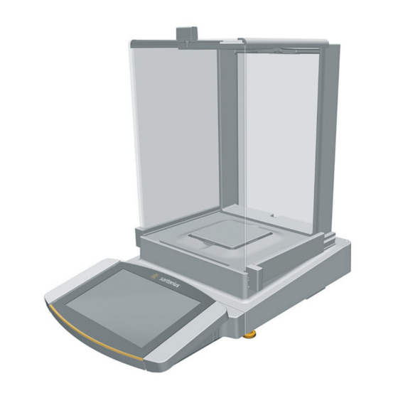
Device Description Device Description Device Overview Fig . 1: Semi-microbalance with motorized draft shield with ionizer and electronics module (example) Pos. Name Description Weighing chamber Manufacturer’s ID label Not depicted Weighing module Electronics module Only for semi-microbalances with electronics module Leveling foot Motorically adjustable Palm-operated key... -
Page 12: Draft Shield
Device Description Draft Shield Fig . 2: Precision balance with frame draft shield, analytical balance with motorized analytical draft shield, and precision balance with manual analytical draft shield (example) Pos. Name Description Frame draft shield Is placed on the shield plate . Analytical draft shield Can be opened at the door handle of the upper panel or at the door handles of the side panels . -
Page 13: Weighing Pan And Associated Components
Device Description Weighing Pan and Associated Components Fig . 3: Precision balance with frame draft shield, analytical balance with manual analytical draft shield, and precision balance with manual analytical draft shield (example) Pos. Name Description Weighing pan Pan support Only for models with pan support Shield plate Pan retainer Cubis... -
Page 14: Weighing Module
Access switch Protects the device from changes to the device settings . Is sealed for conformity- assessed devices . Peripheral connection For connecting Sartorius accessories Power supply For connection to the power supply Slot For attaching a “Kensington” anti-theft device 3.4.2... -
Page 15: Electronics Module
Access switch Protects the device from changes to the device settings . Is sealed for conformity- assessed devices . Peripheral connection For connecting Sartorius accessories Weighing module connection For connecting the electronics module to the weighing module Power supply For connection to the power supply Connections on the Display and Control Unit Fig . -
Page 16: Safety Equipment
Device Description Safety Equipment 3.7.1 Protective Caps on the Analytical Balance and Precision Balance Fig . 8: Protective caps on the weighing module of the analytical balance and precision balance Pos. Name Description Protective cap for USB-A connection Plastic attachment hood, fastened to the device . Protective cap for USB-B connection Plastic attachment hood, fastened to the device . -
Page 17: Conformity-Assessed Devices
Device Description Conformity-assessed Devices Some settings of conformity-assessed models are protected against user changes, e .g . “external calibration” for devices in accuracy class II . This measure is intended to ensure the suitability of the devices for use in legal metrology . Symbols on the Device Fig . -
Page 18: Operating Concept
Operating Concept Operating Concept Operating Elements in the Main Menu Fig . 1: Operating elements in the main menu (example) Pos. Name Description Navigation and function bar − Enables navigation and searching in menus and lists . − In the “Settings” Menu: Displays the name of the menu . Available tasks Displays all tasks available for the active user . -
Page 19: Operating Elements In Task Management
Operating Concept Operating Elements in Task Management Fig . 2: Operating elements in Task Management (example) Pos. Name Description Navigation and function bar − Enables navigation and searching in menus and lists . − Enables the addition of tasks . −... -
Page 20: Operating Elements In The Weighing Display
Operating Concept Operating Elements in the Weighing Display Fig . 3: Weighing display (example) Pos. Name Description Application symbol Displays the symbol for the active application . Task name Displays the name of the active task . Date display Displays the current date . User name Displays the name of the active user profile . -
Page 21: Advanced Operator Guidance
Operating Concept Advanced Operator Guidance Advanced applications have advanced operator guidance . Fig . 4: Advanced operator guidance (example) Pos. Name Description Weighing display with operator guidance Advanced operator guidance Guides the user through the active task . Includes 2 or 3 convertible displays depending on the selected application: −... -
Page 22: Messages
Operating Concept Messages Fig . 5: Error message (example) Pos. Name Description Description Specifies the cause . Remedy Specifies the measures necessary to eliminate the cause of the message . Confirm Confirms and closes the message . Message type Indicates that the message is a status message, warning message, or an error message . -
Page 23: Status Center
Operating Concept Status Center Fig . 6: Status Center (example) Pos. Name Description Messages Displays information, warning, and error messages . Leveling status Displays the status of the level . Status for the device Displays the general device information . Calibration and adjustment report Displays the data for the last adjustment and calibration . -
Page 24: Keypad
Operating Concept Keypad The keypad is used for entering values in entry fields . If an entry field is activated: The alphanumeric keypad or numerical keypad appears . Fig . 7: Alphanumeric keypad and numerical keypad (example) Pos. Name Description Entry field Input assistance Indicates which values must be entered in the input field, e .g . -
Page 25: Buttons In The Operating Display
Operating Concept Buttons in the Operating Display 4.9.1 Buttons for Navigation or Organization in Displays Symbol Name Description [Menu] button Quits the active task and opens the main menu . [Back] button − Returns to the previous display . − In the main menu: Accesses the last-performed task . [Search] button Displays options for browsing tasks and list elements . -
Page 26: Buttons For Editing Or Managing Entries
Operating Concept Symbol Name Description [Service Information] button Opens the “Settings” / “Device Settings” / “Device Information” / Service “Service” menu . Information [Status Archive] button Opens an overview of all status messages, warning messages, and Archive error messages . [Leveling] button Opens the Leveling Wizard . -
Page 27: Weighing And Print Function Buttons
Operating Concept Symbol Name Description [Cancel] button − Cancels the current process without saving the changed settings or values . − In the display for editing the print memory: Marks the selected value as invalid . [Edit] button Accesses the Adjustment Wizard for editing the displayed element, e .g . -
Page 28: Displays In The Operating Display
Operating Concept Symbol Name Description [Delete Tare 1] button Deletes the tare 1 memory . [Start] button Starts the selected application . [Quit] button Quits the active application and opens the Print Memory display . [Confirm] button Confirms the current display and initializes the next step . [Save] button Saves the weight value and sends it to the print memory . - Page 29 Operating Concept Symbol Name Description [Invalid weight value] display − Together with the unit, the display shows the calculated weight value of an application, e .g . for the “Totalizing” application . The displayed weight value is less than the specified minimum weight .
-
Page 30: User Management
Operating Concept 4.11 User Management 4.11.1 User Profiles In the factory, 4 user profiles are created for the device . One role is assigned to each user profile . Each role has rights to operate the device . The rights assigned to each role depend on which device functions the user has to use . -
Page 31: Menu Structure
Display the certification body's SHA1 fingerprint . fingerprint HTTPS certificate SHA1 Display the HTTPS certificate’s SHA1 fingerprint . fingerprint Service Service contact Display the responsible contact at Sartorius Service . Telephone number Display the telephone number for Sartorius Service . Cubis ®... - Page 32 Operating Concept Level 1 Level 2 Level 3 Description E-mail Display the e-mail address for Sartorius Service . Hotline Display the technical hotline for Sartorius Service . Contract Display the responsible contact for maintenance measures . Next scheduled maintenance Display the date for the next scheduled maintenance .
- Page 33 Operating Concept Level 1 Level 2 Level 3 Description Timer-controlled Start task Display, edit or delete properties for starting the actions task . Display message Display, edit or delete the message name and content . Standby mode Display, edit or delete execution of the action for standby mode .
- Page 34 Operating Concept Level 1 Level 2 Level 3 Description Website / web services Website access Determines the settings for the display of the website for the device . Remote access Define the settings for controlling the device remotely . Web service password Define the password for the web services .
- Page 35 Operating Concept Level 1 Level 2 Level 3 Description Ionizer Activation ionizer Define the switch-on behavior for the ionizer . Only for devices with an ionizer Intensity Define the intensity of the ionization process . Start-up duration Define the duration of the ionization process in seconds .
-
Page 36: Navigating The Menus
Operating Concept 4.15 Navigating the Menus Procedure To open a menu from the main menu: Tap on the desired menu button in the function bar . The menu opens and the name of the open menu is displayed in the navigation bar . - Page 37 Operating Concept If elements from a display need to be filtered or a display needs to be browsed: Press the [Search] or [Filter] button . The keypad is displayed . Type the searched value or value to be filtered into the entry field (1) using the keypad .
-
Page 38: Installation
Installation Installation Scope of Delivery Item Quantity Device Weighing pan Shield plate For models with pan support: Pan support AC adapter For models with a motorized draft shield: Palm-operated key Country-specific power supply cable with test seal USB connection cable In-use dust cover for display and control unit For models with analytical draft shield: Dust cover For models without a draft shield: In-use dust cover for the weighing... -
Page 39: Unpacking The Device
Installation Unpacking the Device Procedure Lift the device with the styrofoam padding out of the packaging . Place the device in the styrofoam padding on its side . Lift the styrofoam padding off the device . NOTICE Glass breakage due to incorrect handling of the device! Only lift the device by its base . -
Page 40: Connecting The Ethernet Cable
Installation Pull the connection cable between the control unit and the weighing module (1) out of the control unit’s retainer to the required length . Place the device back on the device base on a level surface . Connecting the Ethernet Cable Material: 1 Ethernet cable 1 soft support base... - Page 41 Installation Requirements − The weighing pan and the associated components have not been set up . − For a device with an analytical draft shield or flat glass draft shield: The side panels and upper panel have not been fitted . Procedure Turn the device on its side and place it on the soft support base .
-
Page 42: Installing A Device With An Analytical Draft Shield
Installation Installing a Device with an Analytical Draft Shield or Flat Glass Draft Shield 5.7.1 Positioning the Weighing Pan and Associated Components Procedure If this relates to a device with a pan support: Place the shield plate (1) on the base of the weighing chamber (2) . Hook the pin on the pan support into the clip on the pan retainer . -
Page 43: Installing The Analytical Draft Shield
Installation If this relates to a device without a pan support: Place the shield plate (2) into the weighing chamber . Place the weighing pan (1) into the recess in the shield plate . 5.7.2 Installing the Analytical Draft Shield Procedure Slide the upper panel into the guide rail (1) . -
Page 44: Installing A Device With A Frame Draft Shield
Installation Insert the side panel completely into the guide rails on the weighing module (2) and into the upper guide rails (1) . Installing a Device with a Frame Draft Shield 5.8.1 Positioning the Weighing Pan and Associated Components Procedure Insert the pin on the pan support into the clip on the pan retainer . -
Page 45: Connecting The Electronics Module
Installation Connecting the Electronics Module (Only for Semi-microbalance) Procedure Connect the connection cable to the electronics module’s weighing module connection . Connect the other end of the connection cable to the weighing module’s electronics module connection . To lock the connection cable: Lock the plugs of the connection cable onto both connections with two clicks in each case . -
Page 46: Acclimatization
Installation Rotate the panel 180° so that the recess (1) in the panel points towards the weighing module . Feed the connection cable into the weighing chamber . Insert the panel into the guide groove (1) . Lift the locking tab (1) on the rear panel of the device and push down the panel . Press the locking tab down and close it . -
Page 47: Getting Started
WARNING Severe injuries caused by using a defective power supply cable! Check the power supply cable for damage, e .g ., cracks in the insulation . If required: Contact Sartorius Service . Check whether the country-specific power plug matches the power connections at the installation site . -
Page 48: Attaching The Protective Caps
Getting Started Connect the mains plug of the power supply cable to the wall outlet at the installation site . The [Booting device . . .] display appears in the operating display . The [Starting system . . .] display appears in the operating display . The [Starting application . -
Page 49: System Settings
System Settings System Settings Performing System Settings Default settings can be adjusted for the device and the applications in order to align with the ambient conditions and individual operating requirements . The following settings are necessary to operate the device together with connected components: −... -
Page 50: Setting Up Device For Network Printer
System Settings Setting Up Device for Network Printer 7.4.1 Selecting Configuration for Network Printing Two configurations are possible: − The device and the network printer communicate via an independent Wi-Fi network with standard Wi-Fi components . No security guidelines or network settings need to be taken into consideration here . -
Page 51: Company Network
System Settings 7.4.3 Setting Up Device for Network Printer via Company Network Requirements − The device administrator or service rights are activated via user management . − The company network has a DHCP server . − The network printer is connected to the company network . Procedure Open the “Settings / Connections / Network / Wi-Fi”... -
Page 52: Parameter List
. Language Set the language for the user profile . User color profile Sartorius Standard* If the QAPP extension “Color Scheme” has been activated: Define a user color for the user profile . Login method Determine whether the user password is saved locally on the device or provided by an LDAP network server . -
Page 53: Parameters In The "Timer-Controlled
System Settings 7.5.3 Parameters in the “Timer-Controlled Actions” Menu Parameter Settings Explanation Start task Execution date Activates the date and time for starting the task . Repeat period Repeats in minutes, hours, days, months, or years . Name Saves a name for the timer-controlled action . Sets the execution of the action to cancelable or not cancelable . -
Page 54: Profile / Weighing" Menu
System Settings 7.5.4 Parameters in the “Weighing and Print Profile / Weighing” Menu Parameter Settings Explanation Ambient conditions Very stable Sets the ambient conditions to “very stable”: Activates a fast change in the weight values in the event of a load change with a high output rate . Recommended for the following work environment: −... - Page 55 System Settings Parameter Settings Explanation Stability delay Very short Sets the stability delay to “very short”: The stability symbol is displayed after the stability criterion is reached . Short* Sets the stability delay to “short”: The stability symbol only appears after a short delay in order to provide a reliable result despite fluctuations .
-
Page 56: Or Sbi Direct" Menu
System Settings Parameter Settings Explanation Available resolutions All digits on* “All digits on”: All decimal places are shown in the display . Not available on conformity-assessed devices . Last digit off at load change “Reduced by 1 decimal place for load change”: The last decimal place on the display is switched off until stability is achieved . - Page 57 Prints an entered description, e .g . the name of the print profile . User text 2 Prints an additional entered description . Manufacturer Prints the device manufacturer, e .g . “Sartorius” Model name Prints the device model name . Serial number Prints the device serial number .
-
Page 58: Parameters In The "Connections
System Settings 7.5.6 Parameters in the “Connections / Connectors” Menu Parameter Settings Explanation Connector name Saves the entered name for a USB stick . Destination directory Saves the name of a destination directory . YDP30-NET Connector name Saves the entered name for a USB stick . IP or host Enter the IP or host address for the printer . -
Page 59: Parameters In The "Connections / Website / Web Services" Menu
System Settings 7.5.8 Parameters in the “Connections / Website / Web Services” Menu Parameter Settings Explanation Website access Deactivated Deactivates the display of the website for the device . On, without authentication* Sets the display options of the website for the device to “without authentication”... -
Page 60: Parameters In The "Connections / Interfaces / Usb-B Interface" Menu
System Settings Parameter Settings Explanation Data bits 7 data bits Sets the number of data bits to 7 . 8 data bits* Sets the number of data bits to 8 . Parity Odd* Applies an odd parity . Even Applies an even parity . Does not apply a parity . -
Page 61: Sbi Protocol" Menu
System Settings 7.5.12 Parameters in the “Connections / SBI Protocol” Menu Parameter Settings Explanation Format Value without header The data output only exports the measured value without ID code . Value (with header)* The data output exports the measured value with ID codes . Date &... -
Page 62: Parameters In The "Device Settings
System Settings 7.5.15 Parameters in the “Device Settings / Date and Time” Menu Parameter Settings Explanation NTP configuration NTP operating status Activates or deactivates the time synchronization with the NTP server . Server IP Saves the entered server ID for the NTP server . Set the date and time Date format Sets the date display format to DD/MM/YYYY, MM/DD/YYYY, DD .MM .YYYY, YYYY-MM-DD (ISO)*, YYYY:MM:DD, DD-MMM-YYYY or MMM-DD-YYYY . -
Page 63: Device Id" Menu
System Settings Parameter Settings Explanation Starting point of User input If this extension has been activated in the QAPP center: Define the starting operating range point value . Mark weight values Off* If this extension has been activated in the QAPP center: Deactivates the <... -
Page 64: Electronic Signature" Menu
ON key . Color scheme Sartorius Standard* If the QAPP extension has been activated: Selects the color scheme for the “Sartorius Standard” operating display . Additional color schemes can be unlocked via the QAPP center . * Factory setting Cubis ®... -
Page 65: Sound (Loudspeaker)" Menu
System Settings 7.5.24 Parameters in the “Device Settings / Sound (Loudspeaker)” Menu Parameter Settings Explanation Touch sounds Activated Deactivates the acoustic signal for touch and keypad operation . Deactivated* Activates the acoustic signal for touch and keypad operation . Message sounds Activated Deactivates the acoustic signal for messages . -
Page 66: Operation
Operation Operation Switching the Device On and Off The device only delivers accurate values if it has reached the necessary operating temperature . The warm-up time after switching the device on must therefore be complied with . If the device is being switched on for the first time or if the device is switched on after being reset to factory settings: The Setup Wizard opens . -
Page 67: Leveling The Device
Operation Leveling the Device 8.3.1 Level Device with Motorized Leveling Feet Leveling compensates any inclines at the device’s installation site . If leveling is necessary: The [Leveling] button appears in the weighing display and a message appears in the Status Center . Procedure If the weighing display is displayed: Press the [Leveling] button . -
Page 68: Activating Applications And Adding A Task
Operation Activating Applications and Adding a Task 8.5.1 Activating Applications All applications from the QAPP package “Essentials” are activated for the device at the factory . Additional applications may be activated in the QAPP center . Procedure Open Task Management . Press the [QAPP center] button . -
Page 69: Adding Weighing And Print Profiles To A Task
Operation Adding Weighing and Print Profiles to a Task To be able to use a weighing or print profile: Add a weighing or print profile to a task . Weighing and print profiles can be configured in the Settings menu . Procedure Open Task Management . -
Page 70: Overview Of Calibration, Adjustment
Operation Overview of Calibration, Adjustment, and Linearization During calibration, a calibration weight is used to determine how much the displayed value deviates from the actual value . This deviation is compared against a preset target value . The subsequent adjustment eliminates this deviation . During linearization, the deviation of the values from the ideal characteristic curve is corrected . -
Page 71: Internally Calibrating And Adjusting The Device
Operation If the isoCAL manual start function is set and the [isoCAL] button is displayed as the predominant button in the operating display: Press the [isoCAL] button . If information is displayed stating that the weighing pan is loaded: Unload the weighing pan . -
Page 72: Marking Saved Values As Invalid
Operation Type the sample ID into the entry field . Press the [OK] button . The [Print memory] button appears in the operating display . The weight value and entered IDs are saved . If additional values are to be saved: Remove the sample being weighed . -
Page 73: Exiting The Task
Operation 8.12.5 Exiting the Task Procedure Press the [Exit] or [Menu] button . If additional values are to be saved in the print memory: A dialog for prematurely ending the task appears . To return to the weighing display and print the saved values: Tap on the [Yes] button and print the saved values . -
Page 74: Starting The Ionization Process
Operation 8.14.2 Starting the Ionization Process Requirements The model is equipped with an ionizer . Procedure If the [Ionizer] button appears in the weighing display: Press the [Ionizer] button . The ionization process starts . 8.14.3 Switching Off the Ionizer Procedure Open the “Settings / Device Settings / Ionizer”... -
Page 75: Running The "Statistics" Application
Operation 8.15.2 Running the “Statistics” Application The “Statistics” application saves up to 100 weight values and evaluates these statistically . The following values are saved and exported by the statistics application: − Number of components − Mean value − Standard deviation −... -
Page 76: Cleaning And Maintenance
Cleaning and Maintenance Cleaning and Maintenance Preparing a Device with an Analytical Draft Shield or Flat Glass Draft Shield Procedure Turn the device off . Disconnect the device from the power supply . To do so, disconnect the power supply cable from the wall outlet . Fully open the draft shield side panels and upper panel . -
Page 77: Preparing A Device With A Frame Draft Shield
Cleaning and Maintenance Remove the weighing pan and all associated components from the weighing compartment, e .g . shield plate, pan support . Preparing a Device with a Frame Draft Shield Procedure Turn the device off . Disconnect the device from the power supply . To do so, disconnect the power supply cable from the wall outlet . -
Page 78: Assembling And Connecting The Device
− The software update is saved on a USB mass storage device . Procedure Download the software update from the Sartorius website onto the USB mass storage device . If this relates to a zip file: Unzip the software update on the stick . The files must be saved at root level . -
Page 79: Performing A Qapp Center Update
− The QAPP center update is saved on a USB mass storage device . Procedure Download the QAPP center update from the Sartorius website onto the USB mass storage device . If this relates to a zip file: Unzip the QAPP center update on the stick . The files must be saved at root level . -
Page 80: Malfunctions
. unit and the weighing module . communication with the weighing module . If the problem occurs again: 17, 100 Contact Sartorius Service . 10.2 Troubleshooting Fault Cause Remedy Chapter, page The operating display The device is disconnected . -
Page 81: Decommissioning
Decommissioning 11 Decommissioning 11.1 Decommissioning the Device Procedure Turn the device off . Disconnect the device from the power supply . Disconnect the device from all connected devices and all accessories, e .g . printer or electronics module . If this relates to a device with an analytical draft shield or flat glass draft shield: Remove the draft shield side panels and upper panel (see Chapter “9 .1 Preparing a Device with an Analytical Draft Shield or Flat Glass Draft Shield”, page 76) . -
Page 82: Storage And Shipping
.g . in the original packaging . Transport damage as well as measures for subsequent cleaning and disinfection of the device or device components by Sartorius shall be charged to the sender . WARNING Risk of injury due to contaminated devices Devices contaminated with hazardous materials (nuclear, biological, or chemical –... -
Page 83: Disposal
WARNING Risk of injury due to contaminated devices Devices contaminated with hazardous materials (NBC contamination) will not be accepted by Sartorius for repair or disposal . 14.2 Disposing of Device and Parts 14.2.1 Information on Disposal The device and the device accessories must be disposed of properly by disposal facilities . -
Page 84: Technical Data
Technical Data 15 Technical Data 15.1 Dimensions and Weight 15.1.1 Semi-microbalance With manual draft shield With motorized draft shield Unit Value Value Dimensions Weighing module (L x W x H) 450 x 240 x 373 450 x 240 x 373 Electronics module (L x W x H) 211 x 240 x 56 211 x 240 x 56... -
Page 85: Ambient Conditions
Technical Data 15.2 Ambient Conditions 15.2.1 Installation Site Unit Value Installation site Standard laboratory rooms Installation site according to IEC 60259-1, maximum altitude 3000 above sea level For indoor use only Temperature In operation °C +5–+40 In operation for conformity-assessed devices: See information on the device’s ID plate During storage and transport °C... -
Page 86: Protection Class
Technical Data MCA3203S MCA2203S MCA2203P MCA1203S Unit Value Value Value Value Scope of application as per Directive 2014/31/EU With isoCAL function °C +10–+30 +10–+30 +10–+30 +10–+30 Without isoCAL function °C +17–+27 +17–+27 +17–+27 +17–+27 MCA623S MCA623P MCA323S MCA5202S Unit Value Value Value Value... -
Page 87: Power Supply
Technical Data 15.3 Power Supply 15.3.1 Device Only by Sartorius AC adapter YEPS03-15V0 15.3.2 AC Adapter Unit Value Item No . YEPS03-15V0 Primary AC voltage 100–240 (±10%) Frequency 50–60 (± 5%) Current consumption, maximum 1 .0 Secondary DC voltage at 2 A output current 14 .25–15 .75... -
Page 88: Safety Of Electrical Equipment
Technical Data 15.3.3 Safety of Electrical Equipment According to EN 61010-1/IEC 61010-1 Safety requirements for electrical equipment for measurement, control, and laboratory use – Part 1: General Requirements 15.3.4 Electromagnetic Compatibility Interference resistance Suitable for use in industrial areas Transient emissions Class B Suitable for use in residential areas and areas that are connected to a low voltage network that also supplies... -
Page 89: Metrological Data
Technical Data 15.7 Metrological Data 15.7.1 Models MCA225S | MCA225P | MCA125S | MCA125P MCA225S MCA225P MCA125S MCA125P Unit Value Value Value Value Scale interval (d) 0 .01 0 .01/0 .02/0 .05 0 .01 0 .01 | 0 .1 Maximum capacity (Max) 60/120/220 60 | 120 Repeatability at 5% load... -
Page 90: Models Mca524S | Mca524P
Technical Data 15.7.2 Models MCA524S | MCA524P | MCA324S | MCA324P MCA524S MCA524P MCA324S MCA324P Unit Value Value Value Value Scale interval (d) 0 .1 0 .1/0 .2/0 .5 0 .1 0 .1/0 .2/0 .5 Maximum capacity (Max) 120/240/520 80/160/320 Repeatability at 5% load Standard deviation of the load values, 0 .08... -
Page 91: Models Mca224S | Mca124S
Technical Data 15.7.3 Models MCA224S | MCA124S | MCA5203S | MCA5203P MCA224S MCA124S MCA5203S MCA5203P Unit Value Value Value Value Scale interval (d) 1/2/5 0 .1 0 .1 Maximum capacity (Max) 1200/2400/5200 5200 Repeatability at 5% load Standard deviation of the load values, 0 .07 0 .1 tolerance... -
Page 92: Models Mca3203S | Mca2203S
Technical Data 15.7.4 Models MCA3203S | MCA2203S | MCA2203P | MCA1203S MCA3203S MCA2203S MCA2203P MCA1203S Unit Value Value Value Value Scale interval (d) 1 | 10 Maximum capacity (Max) 1200 3200 2200 1010 | 2200 Repeatability at 5% load Standard deviation of the load values, 0 .7 0 .7 0 .7... -
Page 93: Models Mca623S | Mca623P
Technical Data 15.7.5 Models MCA623S | MCA623P | MCA323S | MCA5202S MCA623S MCA623P MCA323S MCA5202S Unit Value Value Value Value Scale interval (d) 1 | 2 | 5 Maximum capacity (Max) 5200 150 | 300 | 620 Repeatability at 5% load Standard deviation of the load values, 0 .7 0 .7... -
Page 94: Recommended Calibration Weight
Technical Data 15.8 Recommended Calibration Weight MCA225S MCA225P MCA125S MCA125P Unit Value Value Value Value External test weight Recommended accuracy class MCA524S MCA524P MCA324S MCA324P Unit Value Value Value Value External test weight Recommended accuracy class MCA224S MCA124S MCA5203S MCA5203P Unit Value Value... -
Page 95: Models Mca524S | Mca524P | Mca5203S | Mca5203P | Mca3203S
Technical Data 15.9.2 Models MCA524S | MCA524P | MCA5203S | MCA5203P | MCA3203S Unit Value isoCAL is triggered by the following criteria: In the event of a temperature change 1 .5 After a time interval After successful leveling 15.9.3 Models MCA623S | MCA623P | MCA323S | MCA5202S Unit Value isoCAL is triggered by the following criteria:... -
Page 96: Interfaces
Pin 8: Request to Send (RTS) Pin 9: Not used 15.11.2 Specifications for the USB-A Interface Communication: USB host (master) Connectable devices: Sartorius printers, USB memory sticks, USB barcode scanners, USB keyboards 15.11.3 Specifications for the USB-B Interface Communication: USB device (slave) Type of interface: Virtual serial interface (virtual COM-port, VCP) and “PC direct”... -
Page 97: Accessories
YWLAN01MS independent Wi-Fi network, e .g ., operation with a Sartorius network printer YDP30-NET (only for Europe) Wireless nano router, e .g ., for Sartorius network YWLAN02MS printer YDP30-NET for operation in an independent Wi-Fi network (only for Europe) Display cable, 3 m, for separate installation of display... -
Page 98: Hardware For Pipette Calibration
Accessories 16.1.3 Hardware for Pipette Calibration Item Quantity Order number Pipette calibration kit for semi-microbalance and YCP04MS analytical balance; consists of a moisture trap and all necessary adapters 16.1.4 Filter Balance and Antistatic Accessories Item Quantity Order number Antistatic weighing pan, 130 mm diameter, for YWP04MS weighing module for semi-microbalance and analytical balance... -
Page 99: Weighing Accessories
Accessories 16.1.7 Weighing Accessories Item Image Quantity Order number Weighing scoop made from chrome-nickel 641214 steel, L 90 mm x W 32 mm x H 8 mm Flexible sample holder for weighing vessels YFH01MS and filters with diameters of up to 120 mm, replaces the original weighing pan, for semi-microbalance and analytical balance... -
Page 100: Sartorius Service
Sartorius Service 17 Sartorius Service Sartorius Service is available should there be any queries regarding the device . Please visit the Sartorius website (www .sartorius .com) for information about the service addresses, services provided, or to contact a local representative . - Page 101 Conformity Documents Cubis ® MCA Operating Instructions...
-
Page 102: Certificate Of Compliance
Project: Date Issued: 70185847 2018-09-24 Issued to: Sartorius Lab Instruments GmbH & Co. KG Otto-Brenner-Strasse 20 Goettingen, Niedersachsen 37079 GERMANY The products listed below are eligible to bear the CSA Mark shown with adjacent indicators 'C' and 'US' for Canada and US or with adjacent indicator 'US' for US only or without either indicator for Canada only. - Page 103 Conformity Documents Certificate: 70185847 Master Contract: 167555 Project: 70185847 Date Issued: 2018-09-24 APPLICABLE REQUIREMENTS CSA Standards: CAN/CSA-C22.2 No. 61010-1-12 Safety Requirements for Electrical Equipment for Measurement, Control, and Laboratory Use, Part 1: General Requirements UL Standards: UL Std. No. 61010-1 (3 Edition) - Safety Requirements for Electrical Equipment for Measurement, Control, and Laboratory Use - Part 1: General Requirements...
-
Page 104: Fcc Supplier's Declaration Of Conformity
Connections between the device and peripherals must be made using shielded cables in order to maintain compliance with FCC radio frequency emission limits. Any modifications made to this device that are not approved by Sartorius may void the authority granted to the user by the FCC to operate this equipment. - Page 105 Sartorius Lab Instruments GmbH & Co. KG Otto-Brenner-Strasse 20 37079 Goettingen, Germany Phone: +49.551.308.0 www.sartorius.com The information and figures contained in these instructions correspond to the version date specified below. Sartorius reserves the right to make changes to the technology, features, specifications and design of the equipment without notice.
Need help?
Do you have a question about the Cubis MCA125P Series and is the answer not in the manual?
Questions and answers