Siemens SIMATIC NET RUGGEDCOM RSG907R Installation Manual
Rugged
Hide thumbs
Also See for SIMATIC NET RUGGEDCOM RSG907R:
- Installation manual (54 pages) ,
- Installation manual (52 pages) ,
- Installation manual (52 pages)

Related Manuals for Siemens SIMATIC NET RUGGEDCOM RSG907R


Summary of Contents for Siemens SIMATIC NET RUGGEDCOM RSG907R
- Page 1 Installation Manual SIMATIC NET Rugged Ethernet Switches RUGGEDCOM RSG907R Edition 02/2020 https://www.siemens.com...
- Page 2 Preface Introduction Installing the Device SIMATIC NET Device Management Rugged Ethernet Switches RUGGEDCOM RSG907R Communication Ports Technical Specifications Installation Manual Certification 02/2020 C79000-G8976-1387-09...
- Page 3 Note the following: WARNING Siemens products may only be used for the applications described in the catalog and in the relevant technical documentation. If products and components from other manufacturers are used, these must be recommend- ed or approved by Siemens. Proper transport, storage, installation, assembly, commissioning, operation and maintenance are required to ensure that the products operate safely and without any problems.
-
Page 4: Table Of Contents
Accessing Documentation ....................... v Disclaimer of Liability ......................v Registered Trademarks ......................v Training ..........................vi Customer Support ........................vi Contacting Siemens ....................... vii Introduction ........................... 1 Feature Highlights ....................2 Description ......................2 Required Tools and Materials ................. 4 Decommissioning and Disposal ................ - Page 5 Table of Contents Supported Networking Standards ................ 30 Fiber Optic Ethernet Port Specifications ............... 31 Operating Environment ..................31 Mechanical Specifications ..................31 Dimension Drawings ................... 32 Certification ......................... 35 Approvals ......................35 6.1.1 CSA ........................35 6.1.2 CSA/Sira ......................36 6.1.3 European Union (EU) ..................
-
Page 6: Preface
However, deviations between the product and the documentation may exist. Siemens shall not be liable for any errors or omissions contained herein or for conse- quential damages in connection with the furnishing, performance, or use of this ma- terial. -
Page 7: Training
Siemens Sales representative. Customer Support Customer support is available 24 hours, 7 days a week for all Siemens customers. For technical support or general information, contact Siemens Customer Support through any of the following methods: Online Visit http://www.siemens.com/automation/support-request... -
Page 8: Contacting Siemens
Preface Contacting Siemens Contacting Siemens Address Siemens AG Industry Sector 300 Applewood Crescent Concord, Ontario Canada, L4K 5C7 Telephone Toll-free: 1 888 264 0006 Tel: +1 905 856 5288 Fax: +1 905 856 1995 E-Mail ruggedcom.info.i-ia@siemens.com https://www.siemens.com RUGGEDCOM RSG907R Installation Manual, 02/2020, C79000-G8976-1387-09... - Page 9 Preface Contacting Siemens viii RUGGEDCOM RSG907R Installation Manual, 02/2020, C79000-G8976-1387-09...
-
Page 10: Introduction
Ports designated for Redundant Network Access (RNA) – ports A/B and 57 – can be customized with a wide array of Small Form-factor Portable (SFP) trans- ceivers offered by Siemens, making the device flexible to the needs of the redun- dant network application. -
Page 11: Feature Highlights
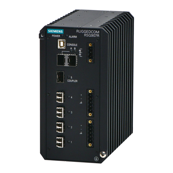
Introduction 1.1 Feature Highlights Feature Highlights Ethernet Ports • 4 x 100Base-FX fiber optic Ethernet ports • 3 x 1000Base-SX/LX SFP transceivers • Industry standard LC fiber optical connectors Rated for Reliability in Harsh Environments • Immunity to EMI and heavy electrical surges •... - Page 12 Introduction 1.2 Description POWER LED ALARM LED USB Console Port RNA Port (Port A/B) Port 5 Fiber Optic Ethernet Ports (Ports 1 to 4) Failsafe Alarm Relay Power Supply Terminal Blocks Chassis Ground Screw Figure 1.1 RUGGEDCOM RSG907R POWER LED Illuminates green when power is supplied to the device. ALARM LED Illuminates red when an alarm condition exists.
-
Page 13: Required Tools And Materials
Introduction 1.3 Required Tools and Materials Required Tools and Materials The following tools and materials are required to install the RUGGEDCOM RSG907R: Tools/Materials Purpose AC power cord (16 AWG) For connecting power to the device. USB Type-B console port cable For connecting to the RUGGEDCOM RUGGEDCOM RSG907R console interface. -
Page 14: Installing The Device
This product contains no user-serviceable parts. Attempted service by unauthorized personnel shall render all warranties null and void. Changes or modifications not expressly approved by Siemens AG could invalidate specifications, test results, and agency approvals, and void the user's authority to operate the equipment. -
Page 15: Installing The Device In Hazardous Locations
2.2 Installing the Device in Hazardous Locations Verify all items are included. NOTICE If any item is missing or damaged, contact Siemens for assistance. Installing the Device in Hazardous Locations The RUGGEDCOM RSG907R is designed to comply with the safety standards for Class I, Division 2, Zone 2 hazardous locations where concentrations of flammable gases, vapors or liquids may be present, as opposed to normal operating environments. -
Page 16: Mounting The Device
Installing the Device 2.3 Mounting the Device IMPORTANT Le remplacement de composants pourrait compromettre l'admissibilité à la Classe I, Division 2. Sample Hazardous Location Label The following is an example of the RUGGEDCOM RSG907R hazardous location label: Figure 2.1 Compliance Label (Example) Mounting the Device The RUGGEDCOM RSG907R is designed for maximum mounting and display flexibili- ty. -
Page 17: 2.3.1 Mounting The Device On A Din Rail
Installing the Device 2.3.1 Mounting the Device on a DIN Rail 2.3.1 Mounting the Device on a DIN Rail The RUGGEDCOM RSG907R can be ordered with a DIN rail adapter preinstalled on the back of the chassis. Use the adapter to mount the device to a standard 35 mm (1.4 in) by 15 mm (0.6 in) IEC/EN 60715 or TS35 DIN rail. -
Page 18: Mounting The Device To A Panel
Installing the Device 2.3.2 Mounting the Device to a Panel Removing the Device To remove the device from a DIN rail, do the following: Insert a flathead screwdriver into the slot of the sliding release and move it down. DIN Rail DIN Rail Adapter Figure 2.3 Removing the Device from a DIN Rail... - Page 19 Installing the Device 2.3.2 Mounting the Device to a Panel To mount the device to a panel, do the following: Secure the mounting adapters to the top and bottom of the device using the four M4 screws each included with the device. Screw (M4) Panel Mount Adapter Figure 2.4...
-
Page 20: Connecting The Failsafe Alarm Relay
Installing the Device 2.4 Connecting the Failsafe Alarm Relay Place the device against the panel and align the adapters with the mounting holes. Screw (M5 or #10-24) Panel Mount Adapter Figure 2.5 Panel Mounting (Rear Mount Orientation) Secure the adapters to the panel with M5 or #10-24 screws. Connecting the Failsafe Alarm Relay The failsafe relay can be configured to latch based on alarm conditions. - Page 21 Installing the Device 2.4 Connecting the Failsafe Alarm Relay To connect the failsafe alarm relay, do the following: Insert the failsafe alarm relay terminal block into the device and tighten the screws. Figure 2.6 Assembling the Failsafe Alarm Relay Terminal Block Connect a failsafe device to the terminal block. Failsafe Alarm Relay Terminal Block Normally Open Common...
-
Page 22: Connecting Power
Installing the Device 2.5 Connecting Power Connecting Power The RUGGEDCOM RSG907R features two input terminals that allow the device to be powered by: • Up to one independent AC and one independent DC power source • Two independent DC power sources IMPORTANT •... - Page 23 Installing the Device 2.5.1 Connecting AC or DC Power Insert the appropriate terminal block(s) into the device and tighten both screws. Power Source Terminal Block Type 3 POS 5 POS Figure 2.8 Assembling the Power Ter- minal Blocks IMPORTANT Torque all terminal connections to 0.6 N·m (5 lbf-in). Connect the power cable to the device as follows: HI Power Supply ...
-
Page 24: 2.5.2 Wiring Examples
Installing the Device 2.5.2 Wiring Examples Connect the ground wire to the chassis/ground terminal on the terminal block. Connect the chassis ground screw to ground (Potential Earth). It is recommend- ed to terminate the ground connection with an M4 ring or spade lug, and then torque to 1.7 N·m (15 lbf-in). - Page 25 Installing the Device 2.5.2 Wiring Examples HI Power Supply Configurations Figure 2.11 Single High AC Power Input Figure 2.12 Single High DC Power Input Configuration Configuration RUGGEDCOM RSG907R Installation Manual, 02/2020, C79000-G8976-1387-09...
- Page 26 Installing the Device 2.5.2 Wiring Examples Figure 2.13 Dual High AC and DC Power Figure 2.14 Dual High DC Power Supplies Supplies RUGGEDCOM RSG907R Installation Manual, 02/2020, C79000-G8976-1387-09...
-
Page 27: Connecting The Device To The Network
Installing the Device 2.6 Connecting the Device to the Network LO Power Supply Configurations Figure 2.15 Single Low DC Power Input Figure 2.16 Dual Low DC Power Input Configuration Configuration Connecting the Device to the Network Steps to connect the device to the network are application-specific. RUGGEDCOM RSG907R Installation Manual, 02/2020, C79000-G8976-1387-09... - Page 28 Installing the Device 2.6 Connecting the Device to the Network Connecting to a Local Area Network In this application, the device operates as a switch on a Local Area Network (LAN). Connect the device as follows: Port Connect To... Not used Not used 5 (Coupler) Connect to an Ether-...
- Page 29 Installing the Device 2.6 Connecting the Device to the Network DAN (RUGGEDCOM RSG907R RSG907R) Figure 2.18 A PRP Network Connecting to an HSR Ring In this application, the device operates as an HSR RedBox in an HSR ring. Connect the device as follows: ...
- Page 30 Installing the Device 2.6 Connecting the Device to the Network Connecting an HSR Ring and PRP Network In this application, the device operates as one of two HSR/PRP RedBoxes in an HSR ring that is connected to either LAN A or LAN B in the PRP network. Connect the de- vice as follows: ...
- Page 31 Installing the Device 2.6 Connecting the Device to the Network Port Connect To... Connect to port B of the neighboring HSR/HSR Red- Box or to the HSR ring Connect to port A of the neighboring HSR/HSR Red- Box or to the HSR ring 5 (Coupler) Connect to the...
-
Page 32: Device Management
Device Management This section describes how to connect to and manage the device. Connecting to the Device The following describes the various methods for accessing the RUGGEDCOM RSG907R console and Web interfaces on the device. For more detailed instructions, refer to the RUGGEDCOM RSG907R User Guide for the RUGGEDCOM RSG907R. IMPORTANT Ethernet cables should be only be connected/disconnected in a non-hazardous area, or when the device is not energized. -
Page 33: Configuring The Device
Device Management 3.2 Configuring the Device Ethernet Ports Connect any of the available Ethernet ports on the device to a management switch and access the RUGGEDCOM RSG907R console and Web interfaces via the device's IP address. The factory default IP address for the RUGGEDCOM RSG907R is https://- 192.168.0.1. -
Page 34: Communication Ports
Communication Ports The RUGGEDCOM RSG907R can be equipped with various types of communication ports to enhance its abilities and performance. Ports A and B Port 5 Ports 1 to 4 Figure 4.1 Port Assignment Port Type SFP Transceiver (1000Base-SX/LX) SFP Transceiver (1000Base-SX/LX) 1 to 4 Fiber Optic (100Base-FX) Ethernet Ports RUGGEDCOM RSG907R... -
Page 35: Redundant Network Access (Rna) Ports
RUGGEDCOM SFP Transceiver Catalog [https://support.industry.siemen- s.com/cs/ca/en/view/109482309] IMPORTANT Only use SFP transceivers approved by Siemens for RUGGEDCOM products. Siemens accepts no liability as a result of performance issues related in whole or in part to third-party components. RUGGEDCOM RSG907R... -
Page 36: Fiber Optic Ethernet Ports
Port Specifications (Page 31)". SFP Transceivers The RUGGEDCOM RSG907R supports up to three Small Form-Factor Pluggable (SFP) transceiver sockets, which are compatible with a wide array of SFP transceivers avail- able from Siemens. RUGGEDCOM RSG907R Installation Manual, 02/2020, C79000-G8976-1387-09... - Page 37 RUGGEDCOM SFP Transceiver Catalog [https://support.industry.siemen- s.com/cs/ca/en/view/109482309] IMPORTANT Only use SFP transceivers approved by Siemens for RUGGEDCOM products. Siemens accepts no liability as a result of performance issues related in whole or in part to third-party components. RUGGEDCOM RSG907R...
-
Page 38: Technical Specifications
Technical Specifications This section provides important technical specifications related to the device. Power Supply Specifications Note When determining cable lengths, make sure the minimum input voltage for the pow- er supply is provided at the power source. Hazardous Environments Power Sup- Input Voltage Internal Isolation... -
Page 39: Failsafe Alarm Relay Specifications
Technical Specifications 5.2 Failsafe Alarm Relay Specifications Failsafe Alarm Relay Specifications Hazardous Environments Maximum Switching Voltage Rated Switching Current Isolation 30 VDC 1500 V for 1 minute 80 VDC 0.3 A 30 VAC 30 VDC 5.0 kVAC between coil and contacts 1.0 kVAC between contacts 250 VAC... -
Page 40: Fiber Optic Ethernet Port Specifications
3 dBm. To convert from peak to average, subtract 3 dBm. • Maximum segment length is greatly dependent on factors such as fiber quality, and the number of patches and splices. Consult a Siemens sales associate when determining maximum segment distances. Operating Environment The RUGGEDCOM RSG907R is rated to operate under the following environmental conditions. -
Page 41: Dimension Drawings
Technical Specifications 5.7 Dimension Drawings Dimension Drawings Note All dimensions are in millimeters, unless otherwise stated. 162.72 Figure 5.1 Overall Dimensions 38.1 163.12 Figure 5.2 Panel Mount Dimensions RUGGEDCOM RSG907R Installation Manual, 02/2020, C79000-G8976-1387-09... - Page 42 Technical Specifications 5.7 Dimension Drawings 162.72 Figure 5.3 DIN Rail Mount Dimensions RUGGEDCOM RSG907R Installation Manual, 02/2020, C79000-G8976-1387-09...
- Page 43 Technical Specifications 5.7 Dimension Drawings RUGGEDCOM RSG907R Installation Manual, 02/2020, C79000-G8976-1387-09...
-
Page 44: Certification
Certification The RUGGEDCOM RSG907R device has been thoroughly tested to guarantee its con- formance with recognized standards and has received approval from recognized reg- ulatory agencies. Approvals This section details the standards to which the RUGGEDCOM RSG907R complies. 6.1.1 This device meets the requirements of the following Canadian and U.S. standards un- der certificate CSA 18CA70171440: •... -
Page 45: 6.1.2 Csa/Sira
Certification 6.1.2 CSA/Sira • ANSI/UL 60079-15:13 Electrical Apparatus for Explosive Gas Atmospheres – Part 15: Type of Protection "n" The device is marked with a CSA symbol that indicates compliance with both Canadi- an and U.S. requirements. It is specifically approved for use in Division 2 and Zone 2 hazardous locations with the following markings: •... -
Page 46: European Union (Eu)
Electromagnetic compatibility of multimedia equipment – Emission requirements The device is marked with a CE marking and can be used throughout the European community. A copy of the CE Declaration of Conformity is available from Siemens AG. For contact information, refer to "Contacting Siemens (Page vii)". -
Page 47: 6.1.4 Fcc
Title 21 Code of Federal Regulations (CFR) – Chapter I – Sub-chapter J – Radiolog- ical Health 6.1.6 ISED This device is declared by Siemens AG to meet the requirements of the following ISED (Innovation Science and Economic Development Canada) standard: • CAN ICES-3 (A)/NMB-3 (A) 6.1.7... -
Page 48: Rra
Republic of Korea (South Korea) as a Class A product in a commercial, industrial or business environment. R-REM-S14-RSG907R A copy of the KC Declaration of Conformity is available from Siemens AG. For contact information, refer to "Contacting Siemens (Page vii)". -
Page 49: Emc And Environmental Type Tests
Certification 6.2 EMC and Environmental Type Tests • EN50121-4 Railway applications – Electromagnetic Compatibility – Emission and Immunity of the Signaling and Telecommunications Apparatus • EN50121-3-2 Railway applications – Electromagnetic Compatibility – Rolling Stock Apparatus • EN 50155 Railway applications – Rolling stock – Electronic equipment EMC and Environmental Type Tests The RUGGEDCOM RSG907R has passed the following Electromagnetic Compatibility (EMC) and environmental tests. - Page 50 Certification 6.2 EMC and Environmental Type Tests Test Description Test Levels Severi- ty Levels Pulse Magnetic Field Enclo- 300 A/m 61000-4-9 sure Ports Voltage Dips and Interrupts AC Pow- 30% for 0.5 Cycles 61000-4-11 er Ports 60% for 5 Cycles 100% for 250 Cycles Mains Frequency Voltage Signal Ports...
- Page 51 Certification 6.2 EMC and Environmental Type Tests Test Description Test Levels IEEE 1613 Oscillatory Signal Ports 2.5 kV Common Mode @ 1 MHz DC Power Ports 2.5 kV Common Mode @ 1 MHz 1 kV Differential Mode @ 1 MHz IEEE 1613 HV Impulse Signal Ports 5 kV (Failsafe Relay)
- Page 52 Further Information Siemens RUGGEDCOM https://www.siemens.com/ruggedcom Industry Online Support (service and support) https://support.industry.siemens.com Industry Mall https://mall.industry.siemens.com Siemens AG Digital Industry Process Automation Postfach 48 48 90026 NÜRNBERG GERMANY...
Need help?
Do you have a question about the SIMATIC NET RUGGEDCOM RSG907R and is the answer not in the manual?
Questions and answers