Siemens SIMATIC NET RUGGEDCOM RSG908C Installation Manual
Hide thumbs
Also See for SIMATIC NET RUGGEDCOM RSG908C:
- Installation manual (48 pages) ,
- Equipment manual (44 pages) ,
- Installation manual (46 pages)

Related Manuals for Siemens SIMATIC NET RUGGEDCOM RSG908C


Summary of Contents for Siemens SIMATIC NET RUGGEDCOM RSG908C
- Page 1 Edition 04/2022 Installation Manual SIMATIC NET Rugged Ethernet Switches RUGGEDCOM RSG908C https://www.siemens.com/ruggedcom...
- Page 2 Preface Introduction Installing the Device SIMATIC NET Device Management Rugged Ethernet Switches RUGGEDCOM RSG908C Communication Ports Technical Specifications Installation Manual Certification 04/2022 C79000-G8976-1404-11...
- Page 3 Note the following: WARNING Siemens products may only be used for the applications described in the catalog and in the relevant technical documentation. If products and components from other manufacturers are used, these must be recommended or approved by Siemens. Proper transport, storage, installation, assembly, commissioning, operation and maintenance are required to ensure that the products operate safely and without any problems.
-
Page 4: Table Of Contents
Accessing Documentation ....................... v Registered Trademarks ......................v Warranty ..........................vi Training ..........................vi Customer Support ........................vii Contacting Siemens ....................... vii Introduction ........................... 1 Feature Highlights ....................1 Description ......................2 Required Tools and Materials ................. 3 Decommissioning and Disposal ................3 Installing the Device ...................... - Page 5 Table of Contents Fiber Optic Ethernet Port Specifications ............... 27 Operating Environment ..................27 Mechanical Specifications ..................27 Dimension Drawings ................... 28 Certification ......................... 31 Approvals ......................31 6.1.1 CSA ........................31 6.1.2 CSA/Sira ......................32 6.1.3 European Union (EU) ..................33 6.1.4 FCC ........................
-
Page 6: Preface
SIMATIC NET Glossary The SIMATIC NET Glossary describes special terms that may be used in this document. The glossary is available online via Siemens Industry Online Support (SIOS) at: https://support.industry.siemens.com/cs/ww/en/view/50305045 Accessing Documentation The latest user documentation for RUGGEDCOM RSG908C is available online at https://support.industry.siemens.com. -
Page 7: Warranty
Warranty Siemens warrants this product for a period of five (5) years from the date of purchase, conditional upon the return to factory for maintenance during the warranty term. This product contains no user-serviceable parts. Attempted service by unauthorized personnel shall render all warranties null and void. -
Page 8: Customer Support
Preface Customer Support Customer Support Customer support is available 24 hours, 7 days a week for all Siemens customers. For technical support or general information, contact Siemens Customer Support through any of the following methods: Online Visit http://www.siemens.com/automation/support-request to submit a Support Request (SR) or check on the status of an existing SR. - Page 9 Preface Contacting Siemens viii RUGGEDCOM RSG908C Installation Manual, 04/2022, C79000-G8976-1404-11...
-
Page 10: Introduction
• Removable SFP Transceivers Ports 5 to 8 can be customized with a wide array of 1000Base-X Small Form- factor Portable (SFP) transceivers offered by Siemens, making the device flexible to the needs of the redundant network application. • Fixed Ethernet Ports In addition to removable SFP transceivers, the device also features four standard 100Base-FX fixed fiber optic Ethernet ports for Local Area Network (LAN) access. -
Page 11: Description
Introduction 1.2 Description • Industry standard LC fiber optical connectors Rated for Reliability in Harsh Environments • Immunity to EMI and heavy electrical surges • Certified for use in explosive environments in accordance with the ATEX directive • Hazardous Location Certification: Class I Division 2 •... -
Page 12: Required Tools And Materials
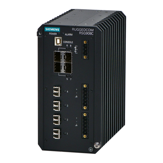
Introduction 1.3 Required Tools and Materials Failsafe Alarm Relay Power Supply Terminal Blocks Chassis Ground Screw Figure 1.1 RUGGEDCOM RSG908C POWER LED Illuminates green during boot up and when power is supplied to the device. ALARM LED Illuminates red when an alarm condition exists. Console Port The USB Type-B console port is for interfacing directly with the device and accessing initial management functions. - Page 13 Introduction 1.4 Decommissioning and Disposal Decommissioning This device may include sensitive, proprietary data. Before taking the device out of service, either permanently or for maintenance by a third-party, make sure it has been fully decommissioned. For more information, refer to the associated "Configuration Manual". Recycling and Disposal For environmentally friendly recycling and disposal of this device and related accessories, contact a facility certified to dispose of waste electrical and electronic...
-
Page 14: Installing The Device
This product contains no user-serviceable parts. Attempted service by unauthorized personnel shall render all warranties null and void. Changes or modifications not expressly approved by Siemens Canada Ltd. could invalidate specifications, test results, and agency approvals, and void the user's authority to operate the equipment. -
Page 15: General Procedure
Inspect the package for damage before opening it. Visually inspect each item in the package for any physical damage. Verify all items are included. Note If any item is missing or damaged, contact Siemens for assistance. RUGGEDCOM RSG908C Installation Manual, 04/2022, C79000-G8976-1404-11... -
Page 16: Installing The Device In Hazardous Locations
Installing the Device 2.3 Installing the Device in Hazardous Locations Installing the Device in Hazardous Locations The RUGGEDCOM RSG908C is designed to comply with the safety standards for Class I, Division 2, Zone 2 hazardous locations where concentrations of flammable gases, vapors or liquids may be present, as opposed to normal operating environments. -
Page 17: Mounting The Device
Installing the Device 2.4 Mounting the Device Sample Hazardous Location Label The following is an example of the RUGGEDCOM RSG908C hazardous location label: Figure 2.1 Compliance Label (Example) Mounting the Device The RUGGEDCOM RSG908C is designed for maximum mounting and display flexibility. It can be equipped with adapters that allow it to be attached to a DIN rail or panel. - Page 18 Installing the Device 2.4.1 Mounting the Device on a DIN Rail NOTICE DIN rail mounting is not recommended for constant vibration environments. Mounting the Device To mount the device to a DIN rail, do the following: Hook the top teeth of the adapter onto the DIN rail. Note The adapter features a sliding release with a slot at the bottom for a flathead screwdriver.
-
Page 19: 2.4.2 Mounting The Device To A Panel
Installing the Device 2.4.2 Mounting the Device to a Panel Removing the Device To remove the device from a DIN rail, do the following: Insert a flathead screwdriver into the slot of the sliding release and move it down. DIN Rail DIN Rail Adapter Figure 2.3 Removing the Device from a DIN Rail... - Page 20 Installing the Device 2.4.2 Mounting the Device to a Panel To mount the device to a panel, do the following: Secure the mounting adapters to the top and bottom of the device using the four M4 screws included with the device. Screw (M4) Panel Mount Adapter Figure 2.4...
-
Page 21: Connecting The Failsafe Alarm Relay
Installing the Device 2.5 Connecting the Failsafe Alarm Relay Place the device against the panel and align the adapters with the mounting holes. Screw (M5 or #10-24) Panel Mount Adapter Figure 2.5 Panel Mounting Secure the adapters to the panel with M5 or #10-24 screws. Connecting the Failsafe Alarm Relay The failsafe relay can be configured to latch based on alarm conditions. - Page 22 Installing the Device 2.5 Connecting the Failsafe Alarm Relay To connect the failsafe alarm relay, do the following: Insert the failsafe alarm relay terminal block into the device and tighten the screws. Figure 2.6 Assembling the Failsafe Alarm Relay Terminal Block Connect a failsafe device to the terminal block. Failsafe Alarm Relay Terminal Block Normally Open Common...
-
Page 23: Connecting Power
Installing the Device 2.6 Connecting Power Connecting Power The RUGGEDCOM RSG908C features two input terminals that allow the device to be powered by: • Up to one independent AC and one independent DC power source • Two independent DC power sources NOTICE Electrical hazard –... - Page 24 Installing the Device 2.6.1 Connecting AC or DC Power • Make sure a terminal block is installed in the unused port and that any wires from the secondary terminal block are properly terminated • Make sure the first power source is off before connecting (or disconnecting) a second power source If connecting a secondary power source, make sure the power source currently connected to the device is disabled (e.g.
-
Page 25: 2.6.2 Wiring Examples
Installing the Device 2.6.2 Wiring Examples Connect the ground wire to the 5 POS Terminal Block Chassis/Ground Terminal chassis/ground terminal on the Negative Terminal terminal block. Positive Terminal LO DC Power supply Figure 2.9 Terminal Block Wiring Connect the Positive wire to the positive (+) terminal on the terminal block. - Page 26 Installing the Device 2.6.2 Wiring Examples HI Power Supply Configurations Figure 2.11 Single HI AC Power Input Figure 2.12 Single HI DC Power Input Configuration Configuration RUGGEDCOM RSG908C Installation Manual, 04/2022, C79000-G8976-1404-11...
- Page 27 Installing the Device 2.6.2 Wiring Examples Figure 2.13 Dual HI AC and DC Power Figure 2.14 Dual HI DC Power Supplies Supplies RUGGEDCOM RSG908C Installation Manual, 04/2022, C79000-G8976-1404-11...
- Page 28 Installing the Device 2.6.2 Wiring Examples LO Power Supply Configurations Figure 2.15 Single LO DC Power Input Figure 2.16 Dual LO DC Power Input Configuration Configuration RUGGEDCOM RSG908C Installation Manual, 04/2022, C79000-G8976-1404-11...
- Page 29 Installing the Device 2.6.2 Wiring Examples RUGGEDCOM RSG908C Installation Manual, 04/2022, C79000-G8976-1404-11...
-
Page 30: Device Management
Device Management This section describes how to connect to and manage the device. Connecting to the Device The following describes the various methods for accessing the RUGGEDCOM RSG908C console and Web interfaces on the device. For more detailed instructions, refer to the "RUGGEDCOM ROS Configuration Manual" for the RUGGEDCOM RSG908C. -
Page 31: Configuring The Device
Device Management 3.2 Configuring the Device Ethernet Ports Connect any of the available Ethernet ports on the device to a management switch and access the RUGGEDCOM RSG908C console and Web interfaces via the device's IP address. The factory default IP address for the RUGGEDCOM RSG908C is https://192.168.0.1. -
Page 32: Communication Ports
Communication Ports The RUGGEDCOM RSG908C can be equipped with various types of communication ports to enhance its abilities and performance. Ports 5 to 8 Ports 1 to 4 Figure 4.1 Port Assignment Port Type 5 to 8 SFP Transceiver (1000Base-SX/LX) 1 to 4 Fiber Optic (100Base-FX) Ethernet Ports Fiber Optic Ethernet Ports The RUGGEDCOM RSG908C features four fixed Fiber optic Ethernet ports, each with... -
Page 33: Sfp Transceivers
"RUGGEDCOM SFP Transceiver Catalog [https:// support.industry.siemens.com/cs/ca/en/view/109482309]". Note Only use SFP transceivers approved by Siemens for RUGGEDCOM products. Siemens accepts no liability as a result of performance issues related in whole or in part to third-party components. RUGGEDCOM RSG908C... -
Page 34: Technical Specifications
Technical Specifications This section provides important technical specifications related to the device. Power Supply Specifications Note When determining cable lengths, make sure the nominal input voltage for the power supply is provided at the power source. Hazardous Environments Power Input Voltage Internal Isolation Maximum... -
Page 35: Failsafe Alarm Relay Specifications
Technical Specifications 5.2 Failsafe Alarm Relay Specifications Failsafe Alarm Relay Specifications Hazardous Environments Maximum Switching Voltage Rated Isolation Switching Current 30 VDC 5.0 kVAC between coil and contacts 1.0 kVAC between contacts 250 VAC 5.0 kVAC between coil and contacts 1.0 kVAC between contacts 50 to 60 Hz for 1 minute Non-Hazardous Environment... -
Page 36: Fiber Optic Ethernet Port Specifications
3 dBm. To convert from peak to average, subtract 3 dBm. • Maximum segment length is greatly dependent on factors such as fiber quality, and the number of patches and splices. Consult a Siemens sales associate when determining maximum segment distances. Data... -
Page 37: Dimension Drawings
Technical Specifications 5.7 Dimension Drawings Ingress Protection IP40 Enclosure Die Cast Aluminum Dimension Drawings Note All dimensions are in millimeters, unless otherwise stated. 162.72 Figure 5.1 Overall Dimensions RUGGEDCOM RSG908C Installation Manual, 04/2022, C79000-G8976-1404-11... - Page 38 Technical Specifications 5.7 Dimension Drawings 38.1 163.12 Figure 5.2 Panel Mount Dimensions 162.72 Figure 5.3 DIN Rail Mount Dimensions RUGGEDCOM RSG908C Installation Manual, 04/2022, C79000-G8976-1404-11...
- Page 39 Technical Specifications 5.7 Dimension Drawings RUGGEDCOM RSG908C Installation Manual, 04/2022, C79000-G8976-1404-11...
-
Page 40: Certification
Certification The RUGGEDCOM RSG908C device has been thoroughly tested to guarantee its conformance with recognized standards and has received approval from recognized regulatory agencies. Approvals This section details the standards to which the RUGGEDCOM RSG908C complies. 6.1.1 This device meets the requirements of the following Canadian and U.S. standards under certificate CSA 18CA70171440: •... -
Page 41: 6.1.2 Csa/Sira
Certification 6.1.2 CSA/Sira • ANSI/UL 60079-15:13 Electrical Apparatus for Explosive Gas Atmospheres – Part 15: Type of Protection "n" The device is marked with a CSA symbol that indicates compliance with both Canadian and U.S. requirements. It is specifically approved for use in Division 2 and Zone 2 hazardous locations with the following markings: •... -
Page 42: European Union (Eu)
Electromagnetic compatibility of multimedia equipment – Emission requirements The device is marked with a CE marking and can be used throughout the European community. A copy of the CE Declaration of Conformity is available from Siemens Canada Ltd.. For contact information, refer to "Contacting Siemens (Page vii)". -
Page 43: 6.1.5 Fda/Cdrh
Title 21 Code of Federal Regulations (CFR) – Chapter I – Sub-chapter J – Radiological Health 6.1.6 ISED This device is declared by Siemens Canada Ltd. to meet the requirements of the following ISED (Innovation Science and Economic Development Canada) standard: • CAN ICES-3 (A)/NMB-3 (A) 6.1.7... -
Page 44: Iso
Certification 6.1.9 ISO A copy of the KC Declaration of Conformity is available from Siemens Canada Ltd.. For contact information, refer to "Contacting Siemens (Page vii)". Notices specific to the RRA: WARNING Class A Equipment (Industrial Broadcasting and Communication Equipment) This device complies with the limits of a Class A electromagnetic wave device and is intended for use outside of a residential environment. -
Page 45: Emc And Environmental Type Tests
Certification 6.2 EMC and Environmental Type Tests • EN 50121-3-2 Railway applications – Electromagnetic Compatibility – Rolling Stock Apparatus • EN 50155 Railway applications – Rolling stock – Electronic equipment EMC and Environmental Type Tests The RUGGEDCOM RSG908C has passed the following Electromagnetic Compatibility (EMC) and environmental tests. - Page 46 Certification 6.2 EMC and Environmental Type Tests Test Description Test Levels Severity Levels 60% for 5 Cycles 100% for 250 Cycles Mains Frequency Voltage Signal Ports 30 V Continuous 61000-4-16 300 V for 1 s DC Power 30 V Continuous Ports 300 V for 1 s Ripple on DC Power Supply DC Power...
- Page 47 Certification 6.2 EMC and Environmental Type Tests Test Description Test Levels DC Power Ports 2.5 kV Common Mode @ 1 MHz 1 kV Differential Mode @ 1 MHz IEEE 1613 HV Impulse Signal Ports 5 kV (Failsafe Relay) DC Power Ports 5 kV AC Power Ports 5 kV...
- Page 48 For more information Siemens RUGGEDCOM https://www.siemens.com/ruggedcom Industry Online Support (service and support) https://support.industry.siemens.com Industry Mall https://mall.industry.siemens.com Siemens Canada Ltd. Digital Industries Process Automation 300 Applewood Crescent Concord, Ontario, L4K 4E5 Canada © 2022 Siemens Canada Ltd. Subject to change...
Need help?
Do you have a question about the SIMATIC NET RUGGEDCOM RSG908C and is the answer not in the manual?
Questions and answers