Siemens RUGGEDCOM RSG909R Installation Manual
Rugged ethernet switches, simatic net
Hide thumbs
Also See for RUGGEDCOM RSG909R:
- Installation manual (54 pages) ,
- Installation manual (52 pages) ,
- Installation manual (52 pages)

Related Manuals for Siemens RUGGEDCOM RSG909R


Summary of Contents for Siemens RUGGEDCOM RSG909R
- Page 1 Installation Manual SIMATIC NET Rugged Ethernet Switches RUGGEDCOM RSG909R Edition 02/2020 https://www.siemens.com...
- Page 2 Preface Introduction Installing the Device SIMATIC NET Device Management Rugged Ethernet Switches RUGGEDCOM RSG909R Communication Ports Technical Specifications Installation Manual Certification 02/2020 C79000-G8976-1388-09...
- Page 3 Note the following: WARNING Siemens products may only be used for the applications described in the catalog and in the relevant technical documentation. If products and components from other manufacturers are used, these must be recommend- ed or approved by Siemens. Proper transport, storage, installation, assembly, commissioning, operation and maintenance are required to ensure that the products operate safely and without any problems.
-
Page 4: Table Of Contents
Accessing Documentation ....................... v Disclaimer of Liability ......................v Registered Trademarks ......................v Training ..........................vi Customer Support ........................vi Contacting Siemens ....................... vii Introduction ........................... 1 Feature Highlights ....................2 Description ......................2 Required Tools and Materials ................. 3 Decommissioning and Disposal ................ - Page 5 FCC ........................38 6.1.5 FDA/CDRH ......................38 6.1.6 ISED ........................38 6.1.7 TÜV SÜD ......................38 6.1.8 RRA ........................39 6.1.9 RoHS ........................39 6.1.10 Other Approvals ....................39 EMC and Environmental Type Tests ..............40 RUGGEDCOM RSG909R Installation Manual, 02/2020, C79000-G8976-1388-09...
-
Page 6: Preface
However, deviations between the product and the documentation may exist. Siemens shall not be liable for any errors or omissions contained herein or for conse- quential damages in connection with the furnishing, performance, or use of this ma- terial. -
Page 7: Training
Siemens Sales representative. Customer Support Customer support is available 24 hours, 7 days a week for all Siemens customers. For technical support or general information, contact Siemens Customer Support through any of the following methods: Online Visit http://www.siemens.com/automation/support-request... -
Page 8: Contacting Siemens
Contacting Siemens Address Siemens AG Industry Sector 300 Applewood Crescent Concord, Ontario Canada, L4K 5C7 Telephone Toll-free: 1 888 264 0006 Tel: +1 905 856 5288 Fax: +1 905 856 1995 E-Mail ruggedcom.info.i-ia@siemens.com https://www.siemens.com RUGGEDCOM RSG909R Installation Manual, 02/2020, C79000-G8976-1388-09... - Page 9 Preface Contacting Siemens viii RUGGEDCOM RSG909R Installation Manual, 02/2020, C79000-G8976-1388-09...
-
Page 10: Introduction
Ports designated for Redundant Network Access (RNA) – ports A/B and 57 – can be customized with a wide array of Small Form-factor Portable (SFP) trans- ceivers offered by Siemens, making the device flexible to the needs of the redun- dant network application. -
Page 11: Feature Highlights
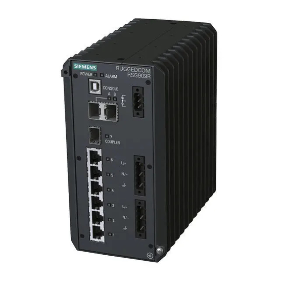
Terminal blocks for reliable maintenance free connections • CSA/UL 60950-1 safety approved to 85 °C (185 °F) Description The RUGGEDCOM RSG909R features various ports, controls and indicator LEDs on the front panel for connecting, configuring and troubleshooting the device. RUGGEDCOM RSG909R Installation Manual, 02/2020, C79000-G8976-1388-09... -
Page 12: Required Tools And Materials
For information about grounding the device, refer to "Con- necting Power (Page 13)". Required Tools and Materials The following tools and materials are required to install the RUGGEDCOM RSG909R: Tools/Materials Purpose AC power cord (16 AWG) For connecting power to the device. -
Page 13: Decommissioning And Disposal
Siemens also does not recommend using copper Ethernet ports to interface with de- vices in the field across distances that could produce high levels of ground potential rise (i.e. -
Page 14: Installing The Device
This product contains no user-serviceable parts. Attempted service by unauthorized personnel shall render all warranties null and void. Changes or modifications not expressly approved by Siemens AG could invalidate specifications, test results, and agency approvals, and void the user's authority to operate the equipment. -
Page 15: Installing The Device In Hazardous Locations
If any item is missing or damaged, contact Siemens for assistance. Installing the Device in Hazardous Locations The RUGGEDCOM RSG909R is designed to comply with the safety standards for Class I, Division 2, Zone 2 hazardous locations where concentrations of flammable gases, vapors or liquids may be present, as opposed to normal operating environments. -
Page 16: Mounting The Device
IMPORTANT Le remplacement de composants pourrait compromettre l'admissibilité à la Classe I, Division 2. Sample Hazardous Location Label The following is an example of the RUGGEDCOM RSG909R hazardous location label: Figure 2.1 Compliance Label (Example) Mounting the Device The RUGGEDCOM RSG909R is designed for maximum mounting and display flexibili- ty. -
Page 17: 2.3.1 Mounting The Device On A Din Rail
2.3.1 Mounting the Device on a DIN Rail The RUGGEDCOM RSG909R can be ordered with a DIN rail adapter preinstalled on the back of the chassis. Use the adapter to mount the device to a standard 35 mm (1.4 in) by 15 mm (0.6 in) IEC/EN 60715 or TS35 DIN rail. -
Page 18: Mounting The Device To A Panel
2.3.2 Mounting the Device to a Panel For panel installations, the RUGGEDCOM RSG909R can be equipped with panel adapters on the top and bottom of the chassis. The adapters allow the device to be attached to a panel using screws. - Page 19 Secure the mounting adapters to the top and bottom of the device using the four M4 screws each included with the device. Screw (M4) Panel Mount Adapter Figure 2.4 Panel Mount Adapter Assembly Prepare mounting holes in the panel where the device is to be installed. RUGGEDCOM RSG909R Installation Manual, 02/2020, C79000-G8976-1388-09...
-
Page 20: Connecting The Failsafe Alarm Relay
Control of the failsafe relay output is configurable through RUGGEDCOM RSG909R . One common application for this relay is to signal an alarm if a power failure oc- curs. For more information, refer to the RUGGEDCOM RSG909R User Guide for the RUGGEDCOM RSG909R. - Page 21 Insert the failsafe alarm relay terminal block into the device and tighten the screws. Figure 2.6 Assembling the Failsafe Alarm Relay Terminal Block Connect a failsafe device to the terminal block. Failsafe Alarm Relay Terminal Block Normally Open Common Normally Closed Figure 2.7 Failsafe Alarm Relay Wiring RUGGEDCOM RSG909R Installation Manual, 02/2020, C79000-G8976-1388-09...
-
Page 22: Connecting Power
Installing the Device 2.5 Connecting Power Connecting Power The RUGGEDCOM RSG909R features two input terminals that allow the device to be powered by: • Up to one independent AC and one independent DC power source • Two independent DC power sources IMPORTANT •... - Page 23 Connect the Positive wire to the Positive Terminal positive (+) terminal on the termi- Figure 2.9 Terminal Block Wiring nal block. Connect the Negative wire to the negative (-) terminal on the termi- nal block. RUGGEDCOM RSG909R Installation Manual, 02/2020, C79000-G8976-1388-09...
-
Page 24: 2.5.2 Wiring Examples
M4 Screw M4 Ring Lug Figure 2.10 Chassis Ground Connection Connect the power cable to the power source. 2.5.2 Wiring Examples The following illustrate how to connect single and dual power supplies to the device. RUGGEDCOM RSG909R Installation Manual, 02/2020, C79000-G8976-1388-09... - Page 25 Installing the Device 2.5.2 Wiring Examples HI Power Supply Configurations Figure 2.11 Single High AC Power Input Figure 2.12 Single High DC Power Input Configuration Configuration RUGGEDCOM RSG909R Installation Manual, 02/2020, C79000-G8976-1388-09...
- Page 26 Installing the Device 2.5.2 Wiring Examples Figure 2.13 Dual High AC and DC Power Figure 2.14 Dual High DC Power Supplies Supplies RUGGEDCOM RSG909R Installation Manual, 02/2020, C79000-G8976-1388-09...
-
Page 27: Connecting The Device To The Network
LO Power Supply Configurations Figure 2.15 Single Low DC Power Input Figure 2.16 Dual Low DC Power Input Configuration Configuration Connecting the Device to the Network Steps to connect the device to the network are application-specific. RUGGEDCOM RSG909R Installation Manual, 02/2020, C79000-G8976-1388-09... - Page 28 Connect to LAN A Connect to LAN B 7 (Coupler) Connect to one or more Singly Attached 1 to 6 Nodes (SANs) VDAN PRP RedBox (RUGGEDCOM RSG909R) LAN B LAN A DAN (RUGGEDCOM RSG909R RSG909R;RSG908C;RSG910C) RUGGEDCOM RSG909R Installation Manual, 02/2020, C79000-G8976-1388-09...
- Page 29 Installing the Device 2.6 Connecting the Device to the Network DAN (RUGGEDCOM RSG909R RSG907R) Figure 2.18 A PRP Network Connecting to an HSR Ring In this application, the device operates as an HSR RedBox in an HSR ring. Connect the device as follows: ...
- Page 30 Connect to LAN A or LAN B 1 to 6 Connect to one or more Singly Attached Nodes (SANs) HSR Ring HSR/PRP RedBox (RUGGEDCOM RSG909R/ RSG908C/RSG910C) HSR/PRP RedBox (RUGGEDCOM RSG907R) PRP Network Figure 2.20 HSR-to-PRP Coupling Connecting HSR Rings In this application, the device operates as an HSR/HSR RedBox in an HSR ring that is connected to another HSR/HSR RedBox.
- Page 31 HSR/ HSR RedBox 1 to 6 Connect to one or more Singly At- tached Nodes (SANs) HSR Ring HSR Quadbox HSR/HSR RedBox (RUGGEDCOM RSG909R/RSG908C/ RSG910C) HSR/HSR RedBox (RUGGEDCOM RSG907R) Figure 2.21 HSR Quadbox RUGGEDCOM RSG909R Installation Manual, 02/2020, C79000-G8976-1388-09...
-
Page 32: Device Management
For Microsoft Windows users, the RUGGEDCOM USB Serial Console driver must be installed on the users workstation before connecting via the USB Type-B console port. For more information, refer to the RUGGEDCOM RSG909R User Guide for the RUGGEDCOM RSG909R. Use the following settings to connect to the port:... -
Page 33: Configuring The Device
Ethernet Ports Connect any of the available Ethernet ports on the device to a management switch and access the RUGGEDCOM RSG909R console and Web interfaces via the device's IP address. The factory default IP address for the RUGGEDCOM RSG909R is https://- 192.168.0.1. -
Page 34: Communication Ports
Communication Ports The RUGGEDCOM RSG909R can be equipped with various types of communication ports to enhance its abilities and performance. Ports A and B Port 7 Ports 1 to 6 Figure 4.1 Port Assignment Port Type SFP Transceiver (1000Base-SX/LX) SFP Transceiver (1000Base-SX/LX) -
Page 35: Redundant Network Access (Rna) Ports
RUGGEDCOM SFP Transceiver Catalog [https://support.industry.siemen- s.com/cs/ca/en/view/109482309] IMPORTANT Only use SFP transceivers approved by Siemens for RUGGEDCOM products. Siemens accepts no liability as a result of performance issues related in whole or in part to third-party components. RUGGEDCOM RSG909R... -
Page 36: Copper Ethernet Ports
Make sure to use SFPs with compatible speeds on ports A and B. Copper Ethernet Ports The RUGGEDCOM RSG909R supports multiple 10/100/1000Base-TX Ethernet ports that allow connection to standard Category 5 (CAT-5) shielded twisted-pair cables with RJ45 male connectors. - Page 37 Transmit Data- or Bi- Directional Reserved BI_DC+ Bi-Direction- (Do Not Connect) Reserved BI_DC- Bi-Direction- (Do Not Connect) Specifications For specifications on the available copper Ethernet ports, refer to "Copper Ethernet Port Specifications (Page 31)". RUGGEDCOM RSG909R Installation Manual, 02/2020, C79000-G8976-1388-09...
-
Page 38: Technical Specifications
88 VDC 300 VDC 125 VDC, 3.15 A 5 kVDC 15.3 W 250 VDC 85 VAC 264 VAC 110 VAC, 3.15 A 5 kVDC 15.5 W 220 VAC Current consumption may vary based on configuration. RUGGEDCOM RSG909R Installation Manual, 02/2020, C79000-G8976-1388-09... -
Page 39: Failsafe Alarm Relay Specifications
Link Aggregation ü IEEE 802.3u ü IEEE 802.3x Flow Control ü ü ü IEEE 802.3z 1000Base-LX ü IEEE Precision Time Protocol (PTP) ü ü ü 1588-2008 Version 2 RUGGEDCOM RSG909R Installation Manual, 02/2020, C79000-G8976-1388-09... -
Page 40: Copper Ethernet Port Specifications
Auto-crossover and auto-polarity. Typical distance. Dependent on the number of connectors and splices. RMS 1 minute. Operating Environment The RUGGEDCOM RSG909R is rated to operate under the following environmental conditions. Ambient Operating Tempera- -40 to 85 °C (-40 to 185 °F) -
Page 41: Dimension Drawings
Technical Specifications 5.7 Dimension Drawings Enclosure Die Cast Aluminum Dimension Drawings Note All dimensions are in millimeters, unless otherwise stated. 162.72 Figure 5.1 Overall Dimensions RUGGEDCOM RSG909R Installation Manual, 02/2020, C79000-G8976-1388-09... - Page 42 Technical Specifications 5.7 Dimension Drawings 38.1 163.12 Figure 5.2 Panel Mount Dimensions 162.72 Figure 5.3 DIN Rail Mount Dimensions RUGGEDCOM RSG909R Installation Manual, 02/2020, C79000-G8976-1388-09...
- Page 43 Technical Specifications 5.7 Dimension Drawings RUGGEDCOM RSG909R Installation Manual, 02/2020, C79000-G8976-1388-09...
-
Page 44: Certification
Certification The RUGGEDCOM RSG909R device has been thoroughly tested to guarantee its con- formance with recognized standards and has received approval from recognized reg- ulatory agencies. Approvals This section details the standards to which the RUGGEDCOM RSG909R complies. 6.1.1 This device meets the requirements of the following Canadian and U.S. standards un- der certificate CSA 18CA70171440: •... -
Page 45: 6.1.2 Csa/Sira
When marked with the following ATEX marking, this device is approved for use in Zone 2 hazardous locations under certificate Sira 18ATEX4069X. Note For the maximum ambient temperature, refer to the hazardous location label affixed to the device. II 3 G Ex nA nC IIC T4 Gc RUGGEDCOM RSG909R Installation Manual, 02/2020, C79000-G8976-1388-09... -
Page 46: European Union (Eu)
Electromagnetic compatibility of multimedia equipment – Emission requirements The device is marked with a CE marking and can be used throughout the European community. A copy of the CE Declaration of Conformity is available from Siemens AG. For contact information, refer to "Contacting Siemens (Page vii)". -
Page 47: 6.1.4 Fcc
Title 21 Code of Federal Regulations (CFR) – Chapter I – Sub-chapter J – Radiolog- ical Health 6.1.6 ISED This device is declared by Siemens AG to meet the requirements of the following ISED (Innovation Science and Economic Development Canada) standard: • CAN ICES-3 (A)/NMB-3 (A) 6.1.7... -
Page 48: Rra
Republic of Korea (South Korea) as a Class A product in a commercial, industrial or business environment. R-REM-S14-RSG909R A copy of the KC Declaration of Conformity is available from Siemens AG. For contact information, refer to "Contacting Siemens (Page vii)". -
Page 49: Emc And Environmental Type Tests
Railway applications – Electromagnetic Compatibility – Rolling Stock Apparatus • EN 50155 Railway applications – Rolling stock – Electronic equipment EMC and Environmental Type Tests The RUGGEDCOM RSG909R has passed the following Electromagnetic Compatibility (EMC) and environmental tests. EMC Type Tests Test Description... - Page 50 EMC Immunity Type Tests per IEEE 1613 Note The RUGGEDCOM RSG909R meets Class 2 requirements for an all-fiber configuration and Class 1 requirements for copper ports. Class 1 allows for temporary communica- tion loss, while Class 2 requires error-free and interrupted communications.
- Page 51 Class 2 IEC 60255-21-2 Shock 30 g @ 11 ms Class 2 IEC 60255-21-2 Bump 10 g @ 16 ms Class 1 IEC 60255-21-3 Seismic Method A Class 2 IEC 60529 Ingress Protection IP4x RUGGEDCOM RSG909R Installation Manual, 02/2020, C79000-G8976-1388-09...
- Page 52 Further Information Siemens RUGGEDCOM https://www.siemens.com/ruggedcom Industry Online Support (service and support) https://support.industry.siemens.com Industry Mall https://mall.industry.siemens.com Siemens AG Digital Industry Process Automation Postfach 48 48 90026 NÜRNBERG GERMANY...
Need help?
Do you have a question about the RUGGEDCOM RSG909R and is the answer not in the manual?
Questions and answers