Siemens RUGGEDCOM RSG920P Installation Manual
Hide thumbs
Also See for RUGGEDCOM RSG920P:
- Installation manual (41 pages) ,
- Installation manual (54 pages) ,
- Equipment manual (54 pages)

Subscribe to Our Youtube Channel
Related Manuals for Siemens RUGGEDCOM RSG920P


Summary of Contents for Siemens RUGGEDCOM RSG920P
- Page 1 Installation Manual SIMATIC NET Rugged Ethernet Switches RUGGEDCOM RSG920P Edition 04/2021 https://www.siemens.com...
- Page 2 Preface Introduction Installing the Device SIMATIC NET Device Management Rugged Ethernet Switches RUGGEDCOM RSG920P Communication Ports Technical Specifications Installation Manual Certification 04/2021 C79000-G8976-1172-07...
- Page 3 Note the following: WARNING Siemens products may only be used for the applications described in the catalog and in the relevant technical documentation. If products and components from other manufacturers are used, these must be recommended or approved by Siemens. Proper transport, storage, installation, assembly, commissioning, operation and maintenance are required to ensure that the products operate safely and without any problems.
-
Page 4: Table Of Contents
Accessing Documentation ....................... v Registered Trademarks ......................v Warranty ..........................v Training ..........................vi Customer Support ........................vi Contacting Siemens ....................... vii Introduction ........................... 1 Feature Highlights ....................1 Description ......................2 Required Tools and Materials ................. 3 Decommissioning and Disposal ................4 Cabling Recommendations .................. - Page 5 FDA/CDRH ......................40 6.1.7 ISED ........................40 6.1.8 ISO ........................41 6.1.9 RRA ........................41 6.1.10 ACMA ........................41 6.1.11 RoHS ........................42 6.1.12 Other Approvals ....................42 EMC and Environmental Type Tests ..............43 RUGGEDCOM RSG920P Installation Manual, 04/2021, C79000-G8976-1172-07...
-
Page 6: Preface
Warranty Siemens warrants this product for a period of five (5) years from the date of purchase, conditional upon the return to factory for maintenance during the warranty term. This product contains no user-serviceable parts. Attempted service by unauthorized personnel shall render all warranties null and void. -
Page 7: Training
Siemens Sales representative. Customer Support Customer support is available 24 hours, 7 days a week for all Siemens customers. For technical support or general information, contact Siemens Customer Support through any of the following methods: Online Visit http://www.siemens.com/automation/support-request... -
Page 8: Contacting Siemens
Contacting Siemens • Submit SRs or check on the status of an existing SR • Contact a local Siemens representative from Sales, Technical Support, Training, etc. • Ask questions or share knowledge with fellow Siemens customers and the support community... - Page 9 Preface Contacting Siemens viii RUGGEDCOM RSG920P Installation Manual, 04/2021, C79000-G8976-1172-07...
-
Page 10: Introduction
Power Management options provide higher reliability for the most important devices on the network when power demands exceed the available supply. The small form factor of the RUGGEDCOM RSG920P allows for installation in space- limited cabinets and on DIN rails. -
Page 11: Description
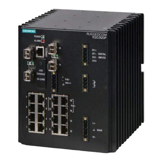
Terminal blocks for reliable maintenance free connections • CSA/UL 62368-1 safety approved to 85 °C (185 °F) Description The RUGGEDCOM RSG920P features various ports, controls and indicator LEDs on the front panel for connecting, configuring and troubleshooting the device. RS-232 Console Port (RJ45) POWER LED... -
Page 12: Required Tools And Materials
"Connecting Power (Page 17)" • "Power Supply Specifications (Page 33)" Required Tools and Materials The following tools and materials are required to install the RUGGEDCOM RSG920P: Tools/Materials Purpose RUGGEDCOM RPS1300 or equivalent 54 VDC For supplying PoE power to the device. -
Page 13: Decommissioning And Disposal
Follow these recommendations for copper data cabling in high electrical noise environments: • Data cable lengths should be as short as possible, preferably 3 m (10 ft) in length. Copper data cables should not be used for inter-building communications. RUGGEDCOM RSG920P Installation Manual, 04/2021, C79000-G8976-1172-07... - Page 14 Power and data cables should intersect at 90° angles when necessary to reduce inductive coupling. • Shielded/screened cabling can be used when required. Care should be taken to avoid the creation of ground loops with shielded cabling. RUGGEDCOM RSG920P Installation Manual, 04/2021, C79000-G8976-1172-07...
- Page 15 Introduction 1.5 Cabling Recommendations RUGGEDCOM RSG920P Installation Manual, 04/2021, C79000-G8976-1172-07...
-
Page 16: Installing The Device
The surface of the device may be hot during operation, or as a result of the ambient air temperature. Wear appropriate personal protective equipment and use caution when working with or around the device. RUGGEDCOM RSG920P Installation Manual, 04/2021, C79000-G8976-1172-07... -
Page 17: General Procedure
The permissible ambient conditions must be complied with. The information in the relevant document must be observed. NOTICE Do not install the RUGGEDCOM RSG920P in a nuclear power plant or other nuclear- related facilities. NOTICE The RUGGEDCOM RSG920P must be located in an area accessible only by qualified service personnel or other authorized users. -
Page 18: Unpacking The Device
If any item is missing or damaged, contact Siemens for assistance. Installing the Device in Hazardous Locations The RUGGEDCOM RSG920P is designed to comply with the safety standards for Class I, Division 2, Zone 2 hazardous locations where concentrations of flammable gases, vapors or liquids may be present, as opposed to normal operating environments. -
Page 19: Mounting The Device
For further details of the device's compliance with Class I, Division 2, Zone 2 standards, refer to "Approvals (Page 37)". Sample Hazardous Location Label The following is an example of the RUGGEDCOM RSG920P hazardous location label: II 3 G Figure 2.1 Compliance Label (Example) Mounting the Device The RUGGEDCOM RSG920P is designed for maximum mounting and display flexibility. -
Page 20: 2.4.1 Mounting The Device On A Din Rail
2.4.1 Mounting the Device on a DIN Rail The RUGGEDCOM RSG920P can be ordered with a DIN rail adapter preinstalled on the back of the chassis. Use the adapter to mount the device to a standard 35 mm (1.4 in)IEC/EN 60715 or TS35 DIN rail. - Page 21 Insert a flathead screwdriver into the slot of the sliding release and move it down. Push the device against the bottom of the DIN rail, then let go of the sliding release to latch the device. RUGGEDCOM RSG920P Installation Manual, 04/2021, C79000-G8976-1172-07...
-
Page 22: Mounting The Device To A Panel
Lift the device off the DIN rail. 2.4.2 Mounting the Device to a Panel For panel installations, the RUGGEDCOM RSG920P can be equipped with panel adapters that allow the device to be attached to a panel in multiple orientations. Note A side mount orientation requires additional adapters. - Page 23 Screw Panel Adapter Figure 2.6 Panel Mounting (Rear Mount Orientation Shown) Install #8 screws (not supplied) to secure the adapters to the panel. RUGGEDCOM RSG920P Installation Manual, 04/2021, C79000-G8976-1172-07...
-
Page 24: Grounding The Device
2.5 Grounding the Device Grounding the Device The RUGGEDCOM RSG920P chassis features a threaded hole for connecting the device to ground (Protective Earth). It is recommended to terminate the ground connection with an #8 ring tongue or spade lug, and then torque to 1.2 N·m (11 lbf- in). -
Page 25: Connecting The Digital Inputs
Failsafe Alarm Relay Wiring Connecting the Digital Inputs The RUGGEDCOM RSG920P offers two independent digital inputs for monitoring external equipment. Each digital input is associated with an alarm that is configured in RUGGEDCOM RSG920P. Depending on the configuration, the associated alarm may be triggered if the digital input is in either the HIGH or LOW state. -
Page 26: Connecting Power
Terminal Block Wiring Connect the negative cable to the DI1/2- terminal. Connecting Power The RUGGEDCOM RSG920P supports a single integrated high AC/DC or low DC power supply, as well as an external power supply for the Power-over-Ethernet (PoE) ports. NOTICE •... -
Page 27: 2.8.1 Connecting High Ac/Dc Power
Figure 2.10 Terminal Block Wiring Connect the neutral/negative wire from the power source to the neutral/ negative (N/-) terminal on the terminal block. Connect the ground wire to the chassis ground terminal on the device. RUGGEDCOM RSG920P Installation Manual, 04/2021, C79000-G8976-1172-07... -
Page 28: Connecting Low Dc Power
33 VDC, the second power source must have a voltage lower than 33 VDC as well. Similarly, if the first power source has a voltage higher than 36 VDC, the second power source must have a voltage higher than 36 VDC. RUGGEDCOM RSG920P Installation Manual, 04/2021, C79000-G8976-1172-07... - Page 29 Positive Terminal Negative Terminal Chassis Ground Terminal Figure 2.12 Terminal Block Wiring - Connecting Dual DC Power Supply Inputs Connect the negative wire from the power source to the negative terminal on the terminal block. RUGGEDCOM RSG920P Installation Manual, 04/2021, C79000-G8976-1172-07...
-
Page 30: 2.8.3 Connecting External Poe Power
Connect the ground wire to the chassis ground terminal on the device. 2.8.3 Connecting External PoE Power The RUGGEDCOM RSG920P supports four 10/100/1000 Mbps Power-over-Ethernet (POE) Ports that require external power. Note For IEC 61850 compliance, use an IEC 61850 compliant PoE power supply with power cabling no longer than 3 m (118 in). - Page 31 (-) terminal on the terminal block. If using an external power supply other than the RUGGEDCOM RPS1300 that has a chassis ground connection, connect the ground terminal on the power supply to the chassis ground terminal on the device. RUGGEDCOM RSG920P Installation Manual, 04/2021, C79000-G8976-1172-07...
-
Page 32: Device Management
The following describes the various methods for accessing the RUGGEDCOM RSG920P console and Web interfaces on the device. For more detailed instructions, refer to the RUGGEDCOM ROS Configuration Manual for the RUGGEDCOM RSG920P. RS-232 Console Port Connect a workstation directly to either the RJ45 or USB Type-B console port to access the boot-time control and RUGGEDCOM RSG920P interfaces. - Page 33 Clear to Send Read to Send Ring Indicator The DSR, DCD and DTR pins are connected together internally. Reserved (do not connect) The CTS and RTS pins are connected together internally. RI is not connected. RUGGEDCOM RSG920P Installation Manual, 04/2021, C79000-G8976-1172-07...
-
Page 34: Configuring The Device
Communication Ports Connect any of the available Ethernet ports on the device to a management switch and access the RUGGEDCOM RSG920P console and Web interfaces via the device's IP address. For more information about available ports, refer to "Communication Ports (Page 27)". - Page 35 Without touching the contacts on the card, insert or remove the microSD card. When installing the card, push the card in until it clicks in place. Install the access plate and tighten the retention screw. Power up the device. RUGGEDCOM RSG920P Installation Manual, 04/2021, C79000-G8976-1172-07...
-
Page 36: Communication Ports
Communication Ports The RUGGEDCOM RSG920P can be equipped with various types of communication ports to enhance its abilities and performance. SFP Transceiver Sockets Copper Ethernet Ports PoE+ Ports Figure 4.1 Port Assignment Port Type 1 to 16 10/100/1000 Mbps Copper Ethernet Ports... - Page 37 RJ45 Ethernet Port Pin BI_DB- Receive Configuration Data- or Bi- Directional BI_DA+ Transmit Data+ or Bi- Directional Reserved BI_DD+ (Do Not Directional Connect) Reserved BI_DD- (Do Not Directional Connect) BI_DA- Transmit Data- or Bi- Directional RUGGEDCOM RSG920P Installation Manual, 04/2021, C79000-G8976-1172-07...
-
Page 38: Sfp Transceivers
Green (Blinking) Activity No link detected Compatible SFP Transceivers For more information about which SFP transceivers are compatible with the RUGGEDCOM RSG920P, as well as instructions for ordering and installation/ removal, refer to the RUGGEDCOM SFP Transceiver Catalog [https:// support.industry.siemens.com/cs/ca/en/view/109482309]. Note Only use SFP transceivers approved by Siemens for RUGGEDCOM products. -
Page 39: Poe Ports
Communication Ports 4.3 PoE Ports PoE Ports The RUGGEDCOM RSG920P supports four Power over Ethernet (POE) ports (ports 13 to 16) powered by an external power supply. Each port complies with the IEEE 802.3at standard. The total allowable power budget for all ports is 120 W. If the external power supply... - Page 40 Transmit Data- or Bi-Directional Reserved (Do BI_DC+ Bi-Directional Not Connect) Reserved (Do BI_DC- Bi-Directional Not Connect) Specifications For specifications on the available PoE ports, refer to "PoE Power Supply Specifications (Page 33)". RUGGEDCOM RSG920P Installation Manual, 04/2021, C79000-G8976-1172-07...
- Page 41 Communication Ports 4.3 PoE Ports RUGGEDCOM RSG920P Installation Manual, 04/2021, C79000-G8976-1172-07...
-
Page 42: Technical Specifications
1.5 kVDC (T) denotes time-delay fuse. Power consumption varies based on configuration. PoE Power Supply Specifications The RUGGEDCOM RSG920P adheres to the following power output and IEEE specifications depending on the input voltage supplied to the device. Power In Power Out... -
Page 43: Digital Input Specifications
-30 ~ + 8 V Wetting Voltage +9.5 V Input/Output Current 5-10 mA Operating Environment The RUGGEDCOM RSG920P is rated to operate under the following environmental conditions. Ambient Operating -40 to 85 °C (-40 to 185 °F) Temperature Ambient Storage Temperature -40 to 85 °C (-40 to 185 °F) -
Page 44: Dimension Drawings
Technical Specifications 5.8 Dimension Drawings Dimension Drawings Note All dimensions are in millimeters, unless otherwise stated. 165.6 152.0 154.0 Figure 5.1 Overall Dimensions Figure 5.2 Panel Mount Dimensions (Rear Mount Shown) RUGGEDCOM RSG920P Installation Manual, 04/2021, C79000-G8976-1172-07... - Page 45 Technical Specifications 5.8 Dimension Drawings 130.3 117.6 79.5 Figure 5.3 Panel Mount Dimensions (Side Mount Shown) Figure 5.4 DIN Rail Mount Dimensions RUGGEDCOM RSG920P Installation Manual, 04/2021, C79000-G8976-1172-07...
-
Page 46: Certification
Certification The RUGGEDCOM RSG920P device has been thoroughly tested to guarantee its conformance with recognized standards and has received approval from recognized regulatory agencies. Approvals This section details the standards to which the RUGGEDCOM RSG920P complies. 6.1.1 This device meets the requirements of the following Canadian Standards Association (CSA) standards under certificate 16.70023156:... -
Page 47: 6.1.2 Csa/Sira
This device is certified by TÜV SÜD to meet the requirements of the following standards: CAN/CSA-C22.2 NO. 62368-1 • Information Technology Equipment – Safety – Part 1: General Requirements (Bi- National standard, with UL 62368-1) RUGGEDCOM RSG920P Installation Manual, 04/2021, C79000-G8976-1172-07... -
Page 48: European Union (Eu)
UL 62368-1 Information Technology Equipment – Safety – Part 1: General Requirements) 6.1.4 European Union (EU) This device is declared by Siemens AG to comply with essential requirements and other relevant provisions of the following EU directives: • 94/9/EC (ATEX) ATEX –... -
Page 49: 6.1.5 Fcc
Certification 6.1.5 FCC A copy of the CE Declaration of Conformity is available from Siemens AG. For contact information, refer to "Contacting Siemens (Page vii)". Notices specific to the European Union: WARNING Communication hazard – risk of radio interference This is a Class A product. In a domestic environment this product may cause radio interference, in which case the user may be required to take adequate measures. -
Page 50: Iso
Republic of Korea (South Korea) as a Class A product in a commercial, industrial or business environment. MSIP-REM-S14-RSG920P A copy of the KC Declaration of Conformity is available from Siemens AG. For contact information, refer to "Contacting Siemens (Page vii)". -
Page 51: 6.1.11 Rohs
A copy of the Declaration of Conformity is available via Siemens Industry Online Support at https://support.industry.siemens.com/cs/ww/en/view/89855782. 6.1.11 RoHS This device is declared by Siemens AG to meet the requirements of the following RoHS (Restriction of Hazardous Substances) directives for the restricted use of certain hazardous substances in electrical and electronic equipment: •... -
Page 52: Emc And Environmental Type Tests
Railway Applications – Fire Protection on Railway Vehicles – Requirements for fire Behavior of Materials and Components EMC and Environmental Type Tests The RUGGEDCOM RSG920P has passed the following Electromagnetic Compatibility (EMC) and environmental tests. EMC Type Tests per IEC 61850-3... - Page 53 AC Power 5 kV Ports Severity level set by Siemens. Common mode tests performed on the signal port shield. For IEC 61850-3 compliance when using Power-over-Ethernet (PoE), an IEC 61850-3 compliant PoE power supply must be installed in the vicinity of the device with power cabling no longer than 3 meters (118 in).
- Page 54 EMC Immunity Type Tests per IEEE 1613 Note The RUGGEDCOM RSG920P meets Class 2 requirements for an all-fiber configuration and Class 1 requirements for copper ports. Class 1 allows for temporary communication loss, while Class 2 requires error-free and interrupted communications.
- Page 55 Certification 6.2 EMC and Environmental Type Tests Test Description Test Levels Severity Levels Bump 10 g at 16 ms Class 1 IEC 60255-21-3 Seismic Method A, Class 2 Class 1 RUGGEDCOM RSG920P Installation Manual, 04/2021, C79000-G8976-1172-07...
- Page 56 Further Information Siemens RUGGEDCOM https://www.siemens.com/ruggedcom Industry Online Support (service and support) https://support.industry.siemens.com Industry Mall https://mall.industry.siemens.com Siemens AG Digital Industry Process Automation Postfach 48 48 90026 NÜRNBERG GERMANY...
Need help?
Do you have a question about the RUGGEDCOM RSG920P and is the answer not in the manual?
Questions and answers