Sign In
Upload
Download
Table of Contents
Contents
Add to my manuals
Delete from my manuals
Share
URL of this page:
HTML Link:
Bookmark this page
Add
Manual will be automatically added to "My Manuals"
Print this page
×
Bookmark added
×
Added to my manuals
Manuals
Brands
Sartorius Manuals
Scales
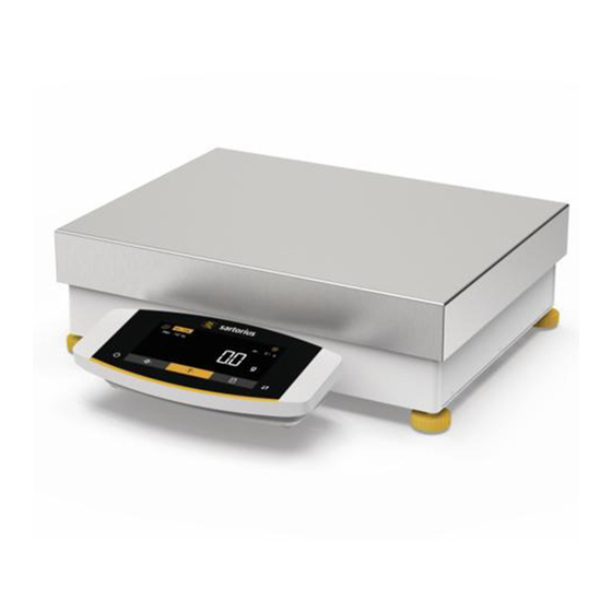
Cubis MCE32202P
Operating instructions manual
Sartorius Cubis MCE32202P Operating Instructions Manual
Hide thumbs
1
2
Table Of Contents
3
4
5
6
7
8
9
10
11
12
13
14
15
16
17
18
19
20
21
22
23
24
25
26
27
28
29
30
31
32
33
34
35
36
37
38
39
40
41
42
43
44
45
46
47
48
49
50
51
52
53
54
55
56
57
58
59
60
61
62
63
64
65
66
67
68
69
70
71
72
73
74
75
76
77
78
79
page
of
79
Go
/
79
Contents
Table of Contents
Troubleshooting
Bookmarks
Table of Contents
Table of Contents
About These Instructions
Scope
Symbols Used
Warnings in Operating Instructions
Other Symbols
Target Groups
Safety Instructions
Intended Use
Modifications to the Device
Repairs to the Device
Personnel Qualification
Significance of These Instructions
Functionality of the Device
Safety Information on the Device
Electrical Equipment
Damage to the Electrical Equipment of the Device
Working on the Device's
AC Adapter and Power Supply Cable
Conduct in an Emergency
Accessories, Consumables, and Spare Parts
Personal Protective Equipment
Glass Breakage
Device Description
Device Overview
Weighing Pan
And Associated Components
Connections and Components
On the Weighing Module
Connections on the Control Unit
Safety Equipment
Protective Caps
Conformity-Assessed Devices
Symbols on the Device
Operating Concept
Operating Display in Weighing Mode
Operating Display in the Menu
Buttons and Keys on the Operating Display
Displays in the Operating Display
Menu Structure
Overview of the Device Settings Menu
Navigating the Menus
Installation
Scope of Delivery
Selecting an Installation Site
Unpacking the Device
Removing the Control Unit
Preparing Below-Cell Weighing
Positioning the Weighing Pan
And Associated Components
Acclimatization
Getting Started
Connecting Electronic Components
Installing the AC Adapter
Connecting the Power Supply
Attaching the Protective Caps
System Settings
Performing System Settings
Switching off the Isocal Function
Parameter List
Parameters in the "Setup" Main Menu
Parameters in the "Device" Main Menu
Parameters in the "Data Output" Main Menu
Parameters in the "Applications" Main Menu
Parameters in the "Input" Main Menu
Parameters in the "Language" Main Menu
Parameters in the "Unit 1", "Unit 2", "Unit 3", and "Unit 4" Function Menus
Operation
Switching the Device on and off
Leveling the Device
Leveling the Device with the Level
Leveling a Device with Manual
Feet with Inclination Sensor
Preparing Weighings
Weighing
Overview of Calibration, and Adjustment
Adjusting with the Isocal Function
Internally Calibrating and Adjusting
The Device
Externally Calibrating and Adjusting
The Device
Assessed Models)
Printing Results
Weighing and Printing with ID Marking
Running Applications (Examples)
Executing the "Toggle between Weight Units
Function
Running the "Statistics
Application
Cleaning and Maintenance
Preparing the Device
Cleaning the Device
Assembling and Connecting the Device
Maintenance Schedule
Performing a Software Update
Malfunctions
Status Messages
Warning Messages
Troubleshooting
Decommissioning
Decommissioning the Device
Transport
Transporting the Device
Storage and Shipping
Storage
Returning Device and Parts
Disposal
Information on Decontamination
Dispose of Device and Parts
Information on Disposal
Technical Data
Dimensions and Weight
High-Capacity Precision Balance
Power Supply
Device
Power Supply Unit
Safety of Electrical Equipment
Electromagnetic Compatibility
Ambient Conditions
Installation Site
Ambient Temperature
For the Isocal Function
Protection Class
Materials
Integrated Clock
Backup Battery
Metrological Data
Models MCE32202P
Mce20201S | Mce11201S
Mce70200S | Mce36200S
Mce36201S
Recommended Calibration Weight
Isocal Function
Models MCE32202P
Mce70200S
Mce36201P | Mce20201S
Mce11201S | Mce36200S
Interfaces
Specifications for the COM-RS232 Interface
Specifications for the USB-A Interface
Specifications for the USB-B Interface
Accessories
Printers and Communication
Displays and Input
Output Elements
Weighing Tables
Weighing Accessories
Sartorius Service
Conformity Documents
Advertisement
Quick Links
1
Table of Contents
2
Technical Data
Download this manual
Operating Instructions
Original Operating Instructions
Cubis
®
MCE Models
High-capacity Precision Balance
1000047944
Table of
Contents
Previous
Page
Next
Page
1
2
3
4
5
Advertisement
Table of Contents
Need help?
Do you have a question about the Cubis MCE32202P and is the answer not in the manual?
Ask a question
Questions and answers
Related Manuals for Sartorius Cubis MCE32202P
Scales Sartorius MC 210 S Installation And Operating Instructions Manual
Analytical, semi-micro- and microbalances (188 pages)
Scales Sartorius Micro MC Series Service Manual
(44 pages)
Scales Sartorius mc1 Installation And Operating Instructions Manual
Electronic semi-micro and analytical balances (136 pages)
Scales Sartorius MC 5 Service Manual
(49 pages)
Scales Sartorius Cubis MCE Series Operating Instructions Manual
Precision balances (71 pages)
Scales Sartorius Cubis MCA Series Operating Instructions Manual
Micro balances (83 pages)
Scales Sartorius Cubis MCA Series Operating Instructions Manual
Microbalances (92 pages)
Scales Sartorius Cubis MCE Operating Instructions Manual
Semi-micro-, analytical and precision balances (98 pages)
Scales Sartorius Cubis MCA Series Operating Instructions Manual
High-capacity precision balances (103 pages)
Scales Sartorius Cubis MCA20201S Operating Instructions Manual
High-capacity precision balances (103 pages)
Scales Sartorius Cubis MCA10202S Series Operating Instructions Manual
Precision balances (89 pages)
Scales Sartorius Cubis MCA4202S Series Operating Instructions Manual
Precision balances (89 pages)
Scales Sartorius Cubis MCA125P Series Operating Instructions Manual
Semimicro, analytical and precision balances (105 pages)
Scales Sartorius Cubis MCE36200S Operating Instructions Manual
(79 pages)
Scales Sartorius Cubis MCA Series Operating Instructions Manual
High-capacity micro balance (94 pages)
Scales Sartorius Cubis MCE Series Operating Instructions Manual
High-capacity micro balance (91 pages)
This manual is also suitable for:
Cubis mce70201s
Cubis mce50201s
Cubis mce36201s
Cubis mce36201p
Cubis mce20201s
Cubis mce11201s
...
Show all
Cubis mce70200s
Cubis mce36200s
Table of Contents
Print
Rename the bookmark
Delete bookmark?
Delete from my manuals?
Login
Sign In
OR
Sign in with Facebook
Sign in with Google
Upload manual
Upload from disk
Upload from URL


Need help?
Do you have a question about the Cubis MCE32202P and is the answer not in the manual?
Questions and answers