Table of Contents
Advertisement
Advertisement
Table of Contents

Subscribe to Our Youtube Channel
Related Manuals for Sartorius MC 5


Summary of Contents for Sartorius MC 5
- Page 1 MC 5 Sartorius Balance Service Manual...
-
Page 2: Table Of Contents
Contents Page Exploded-View Diagram 1 ......................... 4 Exploded-View Diagram 2 ......................... 6 Exploded-View Diagram 3 ......................... 8 Exploded-View Diagram 4 ........................10 Exploded-View Diagram 5 ........................12 Additional Service Tools and Equipment ....................14 Accompanying Literature ......................... 14 General Information ..........................15 Installation Instructions .......................... - Page 3 Description of the Microbalance ......................34 Electronics ............................... 35 Main PCB (Exchanging) .......................... 35 Analog PCB (Exchanging) ........................35 System PCB (Exchanging; Null Indicator Interface) ................35 Data Output PCB ............................ 35 Weight Servomotor PCB ......................... 35 Draft Shield PCB ............................. 35 System Connector PCB ..........................
-
Page 4: Exploded-View Diagram 1
Exploded - View Diagram 1 SARTORIUS MC 5 Balance Stand 1/94... - Page 5 Data output port (interface card) Bracket Analog PCB Space rod Ground plate Leveling foot Display housing Display PCB module Frame for switch pad Switch pad Angular cover plate Holder Cover plate Mylar-backed strip conductor cable Plate Stand 1/94 SARTORIUS MC 5 Balance...
-
Page 6: Exploded-View Diagram 2
Exploded - View Diagram 2 SARTORIUS MC 5 Balance Stand 1/94... - Page 7 Index Designation Top part of housing Draft shield Weighing pan Protective shield plate Disassembling the Draft Shield Base Groundtub Stand 1/94 SARTORIUS MC 5 Balance...
-
Page 8: Exploded-View Diagram 3
Exploded - View Diagram 3 SARTORIUS MC 5 Balance Stand 1/94... - Page 9 System PCB Level indicator Leaf spring fastener Leveling foot Gasket Disk Retaining plate Weight servomotor PCB with system sensor cable Eccentric cam Code disk Drive (servomotor) Lever 316/17 Ball System connector PCB System Disk System Stand 1/94 SARTORIUS MC 5 Balance...
-
Page 10: Exploded-View Diagram 4
Exploded - View Diagram 4 SARTORIUS MC 5 Balance Stand 1/94... - Page 11 Designation 401/08 Guides Lever, factory premounted Leaf spring Preload weights Indifferent equilibrium weight Null indicator subassembly, complete Screw with special thread Cantilever, complete Clamping plate Linkage flexure Linkage Stand 1/94 SARTORIUS MC 5 Balance...
-
Page 12: Exploded-View Diagram 5
Exploded - View Diagram 5 SARTORIUS MC 5 Balance Stand 1/94... - Page 13 Index Designation Curved panel for draft shield Drive Lever Sensor cable (attached to draft shield PCB) 0-ring Bearing ring Centering ring Support disk for bearing shell Bearing shell Thrust ring Cover plate Stand 1/94 SARTORIUS MC 5 Balance...
-
Page 14: Additional Service Tools And Equipment
To service and repair the microbalance, set it up in a clean, stable work area that is free of vibrations and drafts, and use the appropriate tools. In addition to your regular tools, you will need the following special tools to work on the SARTORIUS MC5 Microbalances: No. -
Page 15: General Information
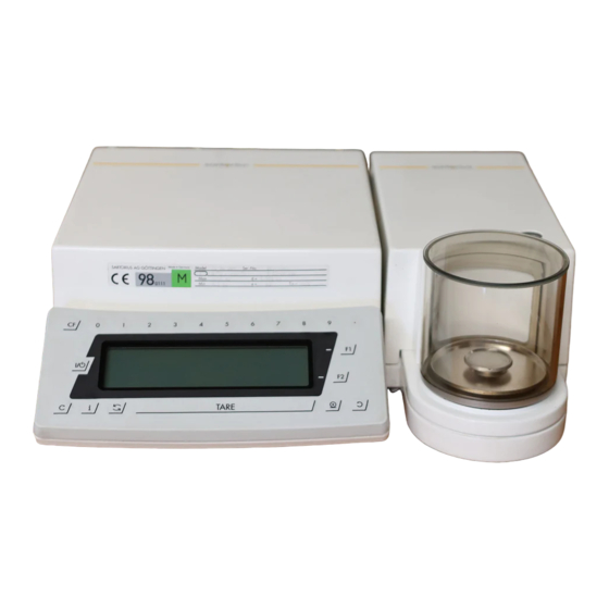
15 Key pad 8 Lug for attaching an anti-theft locking device 16 Metrological ID label ("stamp-/type approved“ models: verified for trade) 9 Male connector on weighing cell 17 Display unit 10 Terminal for equipotential bonding conductor Stand 1/94 SARTORIUS MC 5 Balance... -
Page 16: Installation Instructions
3. Mount the draft shield so that the periphery engages the projected rim. 4. Attach the cable so that both units are directly connected without the cable being kinked. 5. Level the weighing cell using the level indicator. SARTORIUS MC 5 Balance Stand 1/94... -
Page 17: Application Programs
GLP / GMP records/printouts Built-in Interface Port: RS-232 C-S / V24-V28, RS-423 /V 10; 7-bit; even, mark, odd or space parity; transmission speed: 150...19,200 baud; 1 or 2 stop bits; software/hardware handshake Stand 1/94 SARTORIUS MC 5 Balance... -
Page 18: Key Functions
- open toward the >> left << draft shield function key - open toward the >> right << View of the Display and Keypad: 0 - 9 keys (numeric keys) decimal point SARTORIUS MC 5 Balance Stand 1/94... -
Page 19: Accessing The Balance Operating Menu And Setting Menu Codes
- Reset the menu access switch back to "locked“ indicated by >> -L- <<.“ - If you do not want to save changes to the menu codes, exit from the menu by pressing key. Stand 1/94 SARTORIUS MC 5 Balance... -
Page 20: Displaying The Hardware And Software Version Of The Mc5 Microbalance
- The serial number of the particular MC5 microbalance is indicated in the display shown on the left. - Then press the key, and the balance will return to the standard weight display mode. SARTORIUS MC 5 Balance Stand 1/94... -
Page 21: Activating The Bpi Mode
CAS program for PCs in the BPI mode. After operating the microbalance with the PSION server or using the PC CAS program, make sure to reset the interface mode by software command to SBI = Sartorius Balance Interface: PSION = Close PC CAS = Log off Otherwise, peripheral devices will not run on the microbalance’s... -
Page 22: Standard Service Tools And Equipment - Repair Policy
Linearity <=± 0.004mg Calibration 5 g / E1 weight Off-center test weight ø = 8mm Off-center at the edge test area of the pan off-center <=± 0.007mg tolerance Preload test weight Preload -450...-550mV voltage SARTORIUS MC 5 Balance Stand 1/94... -
Page 23: Adjusting The Microbalance
Check and, only if absolutely necessary, adjust the following: 1. Reproducibility 2. Null indicator 3. Preload 4. Indifferent equilibrium 5. Off-center load 6. External linearity 7. External calibration 8. Internal linearity weight (overwrite) 9. Internal calibration weight (overwrite) Stand 1/94 SARTORIUS MC 5 Balance... -
Page 24: Reproducibility
If the standard deviation is >= 1 , you have to check and clean the weighing cell. If the reproducibility error cannot be eliminated by cleaning the weighing cell, the weighing system is defective, and the microbalance must be returned to the factory in Goettingen, Germany. SARTORIUS MC 5 Balance Stand 1/94... -
Page 25: Null Indicator
The preload weights (M 1.4 nuts and washers) are secured by thescrew fastener which is located on top of the null indicator flag.You can change the preload voltage by adding or removing the washers. Stand 1/94 SARTORIUS MC 5 Balance... -
Page 26: Indifferent Equilibrium
- Read off the display and repeat this procedure until the readout is within the tolerances listed below: Zero point error ±0.000005g Sensitivity error for 5g ±0.000005g - If the "!front-to-back“ indifferent equilibrium is out of tolerance, return the microbalance to Sartorius Service Headquarters in Goettingen, Germany. SARTORIUS MC 5 Balance Stand 1/94... -
Page 27: Off-Center Load (Eccentricity)
For the 1st step, measure the off-center loading error at 3 points. Following coarse adjustment, measure the off-center loading error at 5 points and perform fine adjustment, if necessary ( see top diagram). Stand 1/94 SARTORIUS MC 5 Balance... -
Page 28: Linearity
Because of the spread of the measured values, the allowable variation in the linearity for an individual weighing operation is approximately 2 times higher. If the deviations are greater than the allowable tolerances, you will need to adjust the linearity. SARTORIUS MC 5 Balance Stand 1/94... -
Page 29: Adjusting The Linearity
Adjusting the Linearity: Important Note: Whenever possible, linearize the microbalance only by using the PSION server or the Sartorius CAS program written for personal computers and laptops. - Set menu code >> 1-12-1 << - external linearization accessible - on the microbalance (see page 40 of the "Overview of the Balance Operating Program“... -
Page 30: External Calibration
5.0000xx (see Weight Certificate to enter the correct value). - Center the required weight (5g) on the pan and close the draft shield. - After the calibration weight has been stored, the microbalance will return to the standard weighing mode. SARTORIUS MC 5 Balance Stand 1/94... -
Page 31: Overwriting The Internal Linearity Weight
3 readings using a Sartorius external test weight (see Calibration Certificate for weights). Calculate the average for these 3 test readings first, then calculate the allowable deviation range as follows: add this average to the uncertainty of the test weight ±2 times the standard deviation of the... -
Page 32: Overwriting The Internal Calibration Weight
Do not overwrite the internal calibration weight unless you have done the following: run the internal linearization and calibration routines and then take 10 readings using a Sartorius external test weight (see Calibration Certificate for weights). Calculate the average for these 10 test readings first, then calculate the allowable deviation range as follows: add this average to the uncertainty of the test weight ±... -
Page 33: Internal Calibration
- If a printer is connected to the microbalance, a record of this process will be printed on hard copy (for GLP/GMP compliance), depending on the menu code setting (see page 2-31 in the MC5 instruction manual). Stand 1/94 SARTORIUS MC 5 Balance... -
Page 34: Description Of The Microbalance
(see page 4 Exploded-view diagram 1..No.107) Data output PCB (see page 4 Exploded-view diagram 1..No.105) The LCD of the display unit is attached to the following: Display PCB module (see page 4 Exploded-view diagram 1..No.111) SARTORIUS MC 5 Balance Stand 1/94... -
Page 35: Electronics
(display) unit St.28 10-pin To null indicator/system PCB St.27 7-pin weight servomotor PCB St.29 9-pin draft shield PCB Display Module: Similar to the MC1 technology on RC models; with numeric key functions from 0...9. Stand 1/94 SARTORIUS MC 5 Balance... -
Page 36: Power-On Routine And Error Messages
Error Messages On the MC 5, error messages are indicated by a code number. All codes for operating errors, including errors in the sequence of a function, have two-digit numbers. Error codes for hardware errors have three-digit numbers. - Page 37 Run calibration routine calibration range by setting the appropriate calibration menu code. Err 249 EPROM checksum error, Determine the internal calibration weight calibration weight. Err 253 Checksum error, Run the air density air density determination program. Stand 1/94 SARTORIUS MC 5 Balance...
-
Page 38: Draft Shield
- Important note: Make sure to insert the sensor cable (506) through the slot of the system holding plate (319) without pinching the cable. - Allow the microbalance to warm up briefly (wait approx. 30 minutes) so that it will be ready to operate again. SARTORIUS MC 5 Balance Stand 1/94... -
Page 39: Disassembling The Draft Shield Bearing
- Attach the cover plate (516), and mount the shield plate (204), the weighing pan (203) and the draft shield (202). - Allow the microbalance to warm up briefly (wait approx. 30 minutes) so that it will be ready to operate again. Stand 1/94 SARTORIUS MC 5 Balance... -
Page 40: Overview Of The Balance Operating Program
Kilograms 1-7-4 Carats 1-7-5 Pounds 1-7-6 Ounces 1-7-7 Troy ounces 1-7-8 Hon Kong taels 1-7-9 Singapore taels 1-7-10 Taiwanese taels 1-7-11 Grains 1-7-12 Pennyweights 1-7-13 mg Milligrams 1-7-14 Parts/pound 1-7-15 Chinese taels 1-7-16 Mommes SARTORIUS MC 5 Balance Stand 1/94... - Page 41 1-13-2 Access denied 14 Multiple Calibration Mode 1-14-1 1-14-2 15 Auto - Calibr. and Linearization 1-15-1 1-15-2 Cal. status only 1-15-3 1-15-4 Auto-cal. + lin.on 16 Air Density Determination 1-16-1 Accessible 1 16 2 Stand 1/94 SARTORIUS MC 5 Balance...
- Page 42 4 Clear Function with CF 2-4-1 Clear all keys 2-4-2 Clear F1 -> F2 2-4-3 Clear F1 or F2 5 Numeric Keys 2-5-1 Access denied 2-5-2 Accessible without +/- sign 2-5-3 Accessible with +/- sign SARTORIUS MC 5 Balance Stand 1/94...
- Page 43 1 % display accuracy 3-2-1 0.5 % display accuracy 3-2-1 0.2 % display accuracy 3-2-1 0.1 % display accuracy 3-2-1 0.05 % display accuracy 3-2-1 0.02 % display accuracy 3-2-1 0.01 % display accuracy 3-2-1 PolyRange function Stand 1/94 SARTORIUS MC 5 Balance...
- Page 44 3-4-10 0.05 % display accuracy 3-4-11 0.02 % display accuracy 3-4-12 0.01 % display accuracy 3-4-13 PolyRange function 5 Readout in Percent 3-5-1 Without decimal 3-5-2 1 decimal 3-5-4 2 decimals 3-5-4 3 decimals SARTORIUS MC 5 Balance Stand 1/94...
- Page 45 4-1-10 ± 10.0 % 2 Auto Output of OK Values 4-2-1 4-2-2 3 Activation of Port Lines 4-3-1 Within checkweighing range 4-3-2 Always on 4-3-3 At stability + in ch. range 4-3-4 At stability Stand 1/94 SARTORIUS MC 5 Balance...
- Page 46 1 display update 6-3-2 2 display updates 6-3-3 5 display updates 6-3-4 10 display updates 6-3-5 20 display updates 6-3-6 50 display updates 6-3-7 100 display updates 4 Auto Tare after Data Output 6-4-1 6-4-2 SARTORIUS MC 5 Balance Stand 1/94...
- Page 47 Residue in g 7-6-3 Residue in % 7-6-4 Residue in g + % 7 Backw. Rec. w / Difference 7-6-1 7-6-2 Difference in g 7-6-3 Difference in % 7-6-4 Difference in g + % Stand 1/94 SARTORIUS MC 5 Balance...
- Page 48 9 Display Accuracy w. / Draft Shield Auto Open. / Man. Adjus. 8-9-1 Highest accuracy 8-9-2 Rounding factor 2 8-9-3 Rounding factor 5 8-9-4 Rounding factor 10 8-9-5 Rounding factor 20 8-9-6 Rounding factor 50 8-9-7 Rounding factor 100 SARTORIUS MC 5 Balance Stand 1/94...
- Page 49 8 Additional Functions 10 GLP / GMP Printout / Record 8-10-1 8-10-2 Only for cal. functions 8-10-3 Always on 9 Reset Function 9-1-1 Active 9-1-2 Stand 1/94 SARTORIUS MC 5 Balance...
Need help?
Do you have a question about the MC 5 and is the answer not in the manual?
Questions and answers