Table of Contents
Advertisement
Quick Links
Advertisement
Chapters
Table of Contents

Related Manuals for Sartorius mc1


Summary of Contents for Sartorius mc1
- Page 2 WRC 6001-e94013 S a r t o r i u s R e s e a r c h S e r i e s Electronic Semi-Micro and Analytical Balances Installation and Operating Instructions...
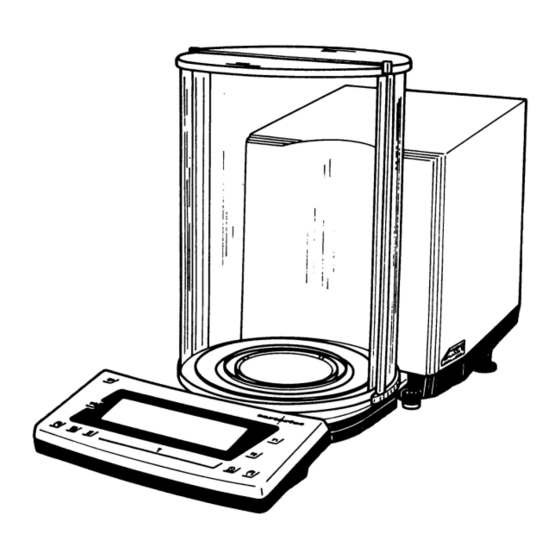
- Page 3 Terminal for connecting an equipotential bonding Large draft shield cover conductor Small draft shield cover Lug for attaching the antitheft locking device Exterior draft shield element, semi cylindrical Metrological label (only *D1-Models) (can be moved by hand) Manufacturer's label Interior draft shield door, semi cylindrical (can be Weight and Information display moved by motor control or by hand) - function key...
-
Page 4: Table Of Contents
Contents Page Page Warranty Calibration and Linearization Storage and Shipping Conditions Fully Automatic Calibration Transporting the Balance Internal Calibration External! Calibration Equipment Supplied Calibration Test Internal Linearization Installation instructions Ambient Conditions For additional functions if you want to Getting Started do more than "just weigh,"... -
Page 5: Warranty
With this Sartorius Balance, you have acquired a high-quality electronic weighing instrument that will ease your daily workload. Please read these Installation and operating instructions carefully before you be- gin to operate your new balance. In "Part l: Installation and Operating Instructions," it is assumed that you are us- ing the factory-set menu codes. -
Page 6: Storage And Shipping Conditions
Storage and Shipping Conditions Allowable storage temperature: +5 °C. ..+40 °C +41 °F...+104 °F The packaging has been designed to ensure that the balance will not be damaged even if it is dropped from a height of 80 cm (about 32 inches). After unpacking the balance, please check it immediately for any visible damage as a result of rough h and 1during shipment. -
Page 7: Equipment Supplied
Equipment Supplied The equipment supplied includes the components listed below: Balance — Power supply — Weighing pan — Shield disk — Protective ring — Interior weighing chamber draft shield — (depending on the balance model) 2 draft shield covers — Dust cover for the draft shield and balance housing —... -
Page 8: Installation Instructions
Installation Instructions Ambient Conditions Unfavourable ambient conditions may affect the weight readouts. Therefore, choose a suitable place to set u p your balance. lt should not be ex- posed to the following: Extreme heat radiation — Drafts — Extreme- vibrations —... -
Page 9: Getting Started
Getting Started Place the components listed below inside the weighing chamber one at a time in the Order given: - shield disk (8) - weighing pan (7) - protective ring (6) - interior weighing chamber draft shield (depending on the balance model) (5) Place the small draft shield cover (2) on top of the semi cylindrical interior draft shield door (4). -
Page 10: Connecting The Balance To Line Voltage
Standard you use, please contact your Sartorius Office or dealer. -
Page 11: Safety Precautions
Safety Precautions The power supply rated to Class 2 can be plugged into a wall outlet without tak- ing any additional safety precautions. The pole of the Output voltage is connected to the balance housing, which can be grounded for Operation. The interface (see "Interfacing Devices"... -
Page 12: Information On Weighing Electro Statically Charged Samples
Information on Weighing Electro statically Charged Samples Problems with static electricity can occur in environments with low humidity. To avoid these problems when you use your balance in such an area, wipe down the entire draft shield on both the inside and outside with a commercially available antistatic agent. -
Page 13: How To Operate The Balance
How to Operate the Balance After initially connecting the balance to line power (or after a relatively long power outage), allow for at least 2 hours' warmup. Working with the Research Series Balance requires a smooth, uninterrupted tech- nique. The weight display shows the following special codes for your information: The balance was disconnects from line power (power failure or outage;... -
Page 14: Turning The Display On And Off (Standby Mode)
Important Note lf the symbol flashes, this means that the balance wants to self-calibrate. You do not need to interrupt your weighing procedure, because the balance will wait until it detects that you have stopped weighing for one complete minute. Afterwards, the balance will perform fully automatic infernal calibration. -
Page 15: Opening And Closing The Draft Shield Door
Opening and Closing the Draft Shield Door If you are loading small objects, open the draft shield only as far as is absolutely necessary for your application. This reduces the amount of draft so your balance will stabilize faster than it normally would when the draft shield is wide-open. - Page 16 Press the key (22] to have the draft shield door closed by motor. While closing, the door moves slowly. The previously adjusted aperture angle is stored in the process. Now if you press the key (22) again, the draft shield door will open at a faster speed to the Position you selected.
-
Page 17: Weighing
Weighing Place your sample on the weighing pan (7) to determine the weight, and dose the draft shield door (for example, by pressing the key (22). Do not read off the weight indicated in the display (18) until the weight unit (in this case “g” or a dif- ferent unit selected - see "Part III: Balance Operating Menu"} appears as the sta- bility symbol. -
Page 18: Weighing Range Structure
Weighing Range Structure SuperRange - "SingleWide-Range Balance" (identified by S in the model designation RC...S) SuperRange models have an extraordinarily high resolution, i.e., the weighing range has a resolution ranging u p to a few million digits. There is one level of fine readability for the entire weighing range [for example: 0.01 mg). -
Page 19: Weighing In The Iq-Mode
Weighing in the IQ-Mode™ (Load-Dependent Readability) In the IQ-Mode™ (IQ = Intelligently quick), weighing is done with a load- dependent readability of 0.01 % (for different settings, see "Part III: Balance Op- erating Menu') throughout the entire weighing range of the balance. The display resolution of the last digit changes in increments of 1, 2, 5, 10, 20, etc. -
Page 20: Mass Unit Conversion By Toggling
Mass Unit Conversion by Toggling You can have the weight displayed in grams or milligrams. To select the three weighing ranges one after the other, press the toggle key (25] each time. In addition to grams and milligrams, this balance gives you a wide variety of other menu-definable international weight unit options. -
Page 21: Calibration And Linearization
Calibration and Linearization During calibration, the balance is adapted to changes in ambient conditions. You should recalibrate your balance each lime you set it up in a different area or when the ambient conditions change (fore example, temperature or barometric pressure). -
Page 22: Fully Automatic Calibration
Fully Automatic Calibration lf the symbol flashes, this means that the balance wants to self--calibrate. You do not need 1o interrupt your weighing procedure, because the balance will wait until it detects that you have stopped weighing for one complete minute. Afterwards, the balance will perform fully automatic internal calibration. -
Page 23: Internal Calibration
INTERNAL CALIBRATION Quick-CAL Function using the key: Unload the pan, close the draft shield and tare. When the balance displays a zero readout, press the key (20). "C" will now be displayed. The built-in calibration weights are internal~ applied by servomotor and removed at the end of calibration. lf external interference affects the calibration procedure, you may obtain a brief display of the error message "Err 02."... -
Page 24: External Calibration
EXTERNAL CALIBRATION Use only calibration weights that have tolerances equal or better than those of ac- curacy class E2 (for 200 g -> ±0.3 mg). Press the tare control (24) for a1 least 2 seconds until "C.l." and “CAL” are dis- played (next to the key). -
Page 25: Calibration Test
CALIBRATION TEST Rather substantial changes In barometric pressure and temperature may affect t he display response of these highly accurate Research Series balances. To ensure that you obtain the full accuracy of these balances, even when you use the entire weighing range, we have implemented a calibration lest function. It will help you decide whether o r not you need to recalibrate your balance (for exam- ple, to maintain the same accuracy during long-term weighing series). -
Page 26: Internal Linearization
INTERNAL LINEARIZATION Press the tare control {24) for at least 2 seconds until "C.l." and “CAL” are dis- played (next to the key). Select "internal linearization" by pressing the key (21} three times until "L.l." is displayed. Unload the balance, make sure the draft shield is closed and tare. "L.l."... -
Page 27: Data Interface
Data Interface lf you wish to record weight data using a Sartorius Data Printer or process them using "Data Control," plug the printer connector into the interface port (14} of the balance. You do not need to adjust any settings! Remove the protective cap from the data interface port. -
Page 28: Interfacing Devices With The Balance
Interfacing Devices with the Balance Please note that the interface port is electrically connected lo the protective grounding conductor of the balance housing. The interface cables supplied as Standard equipment are shielded, and both ends of each cable are electrically connected to the connector cases. -
Page 29: Below-Balance Weighing
Below-Balance Weighing A port for a below-balance weighing hanger is available on the bottom of the balance. To fasten the hanger, open the below-balance port by removing the two screws on the bottom of the balance and detaching the closing plate. Now you can attach a sample using a Suspension wire, for example. -
Page 30: Troubleshooting Guide
Troubleshooting Guide Problem … Causes … Solution No segments appear in the weight No line power available Check power supply — — display (19) The power supply is not plugged in Plug in the power supply — — The display shows “Err 54” or ”L” The weighing pan (7) is not in place Position the pan —... -
Page 31: Care And Maintenance
Care and Maintenance Before cleaning the balance, unplug the power supply from the wall outlet. Cleaning the Balance Housing and the Draft Shield Please do not use any aggressive cleaning agents (solvents or similar agents]. In- stead, use a piece of lint-free cloth which has been wet with a mild detergent. Clean the semi cylindrical elements of the draft shield with a commercially avail- able glass cleaning agent. -
Page 32: Safety Inspection
Ion g periods under unfa- — vourable conditions In this case, notify your nearest Sartorius Service Center or the International Ser- vice Support Department based in Goettingen, Germany. Only service technicians who have access to the required maintenance manuals are allowed to perform maintenance and repair work on the equipment. -
Page 33: Safety Certificate
Safety Certificate Pursuant to the German Directive for the Implementation of Regulations for Prevention of Accidents "Elektrische Anlagen und Betriebsmittel (VBG 4)" (Electrical Installations and Equipment] of April 1986, in conjunction with Article 10 of the Low-Voltage Directive 73/23/EEC issued on February IS, 1973, by the European Community it is hereby certified hat the equipment delivered, "Electronic Semi-Microbalance or Analytical Balance of the RC Series,"... - Page 35 All rights reserved. No part of this publication may be printed or translated in any form or by any means without the prior written permission of Sartorius AG. Sartorius AG reserves the right to make change to the technology, features, specification and design of the equipment without notice.
- Page 36 WRC 6002-e93042 S a r t o r i u s R e s e a r c h S e r i e s Product Data Sheet...
- Page 37 Dimensions (Scale Drawings)
-
Page 38: Specifications
Specifications Model RC 210S RC 210P RC 210D RC 250S Weighing range structure SuperRange PolyRange DualRange SuperRange Capacity/weighing range levels 60 / 110 / 210 52 / 210 Readability 0.01 0.01 / 0.02 / 0.05 0.01 / 0.1 Tare range (by subtraction) -210 -210 -210... - Page 39 Information bulletin 15/88) BalanceReaderSoftware YAK 10 PC-0002 for collecting data that are transmitted by your Sartorius Balance to a commercially available personal Computer. These data are read into spreadsheets and stored. The stored spreadsheets can be further processed using commercially available Standard Software (Excel, Lotus 1-2-3, etc.).
- Page 40 Density determination kit YDK 01 Draft shield cover with pipette opening YDS 01 RC Antistatic pan YWP 01 Weighing bowls Stainless steel bowl, 20 g 6003 Glass bowl, 20 g 6015 Stainless steel bowl with pouring spout, 300 ml 6407 Foot switch with T-connector and three functions YPE 01 RC...
- Page 41 All rights reserved. No part of this publication may be printed or translated in any form or by any means without the prior written permission of Sartorius AG. Sartorius AG reserves the right to make change to the technology, features, specification and design of the equipment without notice.
- Page 42 WRC 6003-e93042 S a r t o r i u s R e s e a r c h S e r i e s Balance Operating Menu...
- Page 43 Overview of the Balance Operating Menu Page How to Access the Menu Examples for Changing Menu Code Settings How to Undo All Menu Code Changes: Reset Function Balance Operating Parameters How to Adapt the Balance to Ambient Conditions Standard Weighing Mode - Manual Filling Mode Stability Range Stability Symbol Delay Tare Parameter...
-
Page 44: How To Access The Menu
How to Access the Menu The Sartorius MC1 Balance can do much more than "just weigh." It can "think" in various units of measure, adapt to unfavourable conditions and process weight data for a variety of applications. In the operating menu, you can define how your balance will adapt to ambient conditions and also how it will work to meet your special requirements. - Page 45 At this point, you'll probably want to know how to change the menu codes stored in your balance. Go right ahead and try to change a few of the menu code settings. That’s the best way to familiarize yourself with the performance capabilities and the versatility of the microcomputer in your Sartorius Balance. Don't worry! Even if you've selected the "wildest"...
- Page 46 Now for a little hands-on practice! It's your turn to try a setting - how about changing the weight unit in the second weighing range (use to select this range) from grams to carats (et), Code: 3 1 4. (In our example, the 1 weighing range "...
-
Page 47: Examples For Changing Menu Code Settings
Examples for Changing Menu Code Settings How to set code 3 1 4 for "ct" in the second weighing range Turn off the balance Turn it back on While all segments are displayed, briefly press the tare control If -L- is displayed, unlock the menu access switch Remove the protective cap located to the left of the AC jack on the rear panel of the balance, and move the switch in the direction of the arrow Change the left-hand number to “3”... - Page 48 That’s all there is to it! Now, if you press the key, you can read the weight in carats "ct": Of course, you'll be in the IQ-Mode™ , with a load-dependent readability of 0.01%, as defined by the factory-set menu code. You say you don't like it? You'd rather weigh in the unit "ct"...
- Page 49 Confirm the code setting Important Note: You must press the tare control in order to .confirm the code you have just set: This is indicated by the "o" after the code. Press to store your menu code setting Now you can read the weight in "ct" accurately down to the last digit. Congratulations! You've just finished the two examples we've given to help famil- iarize you with how to use the code setting function.
-
Page 50: How To Undo All Menu Code Changes: Reset Function
How to Undo All Menu Code Changes - Reset Function The reset function lets you undo all menu code changes, which means that you will obtain the original factory-set menu codes so that your balance will operate according to them. To use this function, you will need to select code 9 - - 1. How to set code: 9 –... - Page 51 Note: The actual menu code setting in the balance operating menu is identified by a small "o" after the last number. When you access the operating menu, the previously set numeric code will be displayed after you select the left and the middle numbers, which means the entire menu code setting is displayed.
-
Page 52: Balance Operating Parameters
Balance Operating Parameters How to Adapt the Balance to Ambient Conditions To adapt your balance to ambient conditions, you may need to change the response time (see the Product Data Sheet). Code Very stable conditions Stable conditions Unstable conditions Very unstable conditions Standard Weighing Mode - Manual Filling Mode You can optimally adapt your balance to meet either of these requirements. -
Page 53: Stability Symbol Delay
Stability Symbol Delay This setting allows your balance to compensate for individual interfering factors which slowly subside, such as turbulent air currents generated within the weighing chamber. Code No delay Short delay long delay Extremely long delay Tare Parameter You can define when the balance will perform the taring Operation: Code At any time not until the readout is stable... -
Page 54: Weighing In Three Ranges
Weighing in Three Ranges The toggle key lets you switch back and forth among three weighing ranges. lf the menu code is set for three ranges, press the key each time to toggle to a different range. How to Select the Number of Ranges Code Block the Two weighing ranges... - Page 55 Overview of the Weight Units: Symbol Code range range range Grams Grams Kilograms Carats Pounds Ounces Troy ounces Hong Kong taels Singapore taels Taiwanese taels Grains Pennyweights Milligrams Codes 1 7 1, 3 1 1 and 3 3 1 are reserved for programming special units to meet the needs of customized applications. The Standard, factory-set unit is grams.
-
Page 56: Iq-Mode
IQ-Mode™ (Load-dependent readability) In the IQ-mode™ , weighing is done with a menu-definable, load-dependent readability throughout the entire weighing range of your balance. In the process, the display resolution of the last weight digit changes in increments of 1, 2, 5, 10, 20, etc., in proportion to the weight of the sample. -
Page 57: Display Modes
Display Modes You can select the display mode that best meets your individual requirements. The menu code settings for all weighing ranges are listed on the next page. Final Readout Mode "- -" lf you are only interested in the final readout, you can select this mode by setting code 2 5 1. A special symbol "- -" will be displayed in any weighing range until the final stable readout appears in digits. - Page 58 Calibration und Linearization Functions Select the appropriate menu code to define the access Status for each of the following calibration and linearization functions, which are activated by holding down the tare control for a few seconds: – External calibration C.E. –...
- Page 59 Multiple Calibration Mode The calibration accuracy can be increased. The calibration values calculated from the average of the individual calibration procedures. You can use the "multiple calibration mode" for both infernal and external calibration. The number of calibration procedures is indicated in the 3rd place of the application display field (e.g., "C 1 5”). Important Note: lf "Err 04"...
- Page 60 Quick CAL with You can activate the "internal calibration" function anytime by a touch of the key (factory setting). That’s why we call it "Quick CAL" for short. You can also set a different menu code to change the function of the key from "internal calibration"...
-
Page 61: Utilities For Printouts Or Data Transfer
Sartorius MC1 Balances come Standard with an interface. You can plug a Sartorius Printer or a Computer into this interface port to print data on hard copy or transfer them to your Computer. Moreover, you can choose to Output data from your balance to this on-line device either automatically or by pressing the print key on the balance. - Page 62 Data Output at Defined Intervals You can reduce the volume of data in the "auto print" mode by defining the interval at which data will be Output automatically. This auto print interval is based on the number of times the display is updated. Auto print interval Code 1 display update...
-
Page 63: Menu Access Function
Additional Functions A number of additional menu codes enable you to assign or deny access to various functions. Menu Access Function You can define the function of the menu access switch by setting the code for the balance operating menu to "accessible." In this setting, "-C-"... -
Page 64: Analog Display: Bar Graph/Marker
Analog Display: Bar Graph/Marker In the factory setting, the analog display works as a bar graph: By changing the menu code, you can turn the analog display completely off or have it appear as a marker. When the marker is selected, two individual Segments will move within the display scale range to indicate the loading Status of your balance. -
Page 65: Fully Automatic Draft Shield Function
Fully Automatic Draft Shield Function You can define the fully automatic draft shield function to meet the most diverse requirements in order to shorten work procedures and make them easier. After you have pressed a function key (or after a control command has been received – see "Part V: Interface Description"), the draft shield will dose automatically and the balance will then perform the particular function activated by the key. - Page 66 Display Accuracy with the Draft Shield Automatically Opened or Manually Adjusted You can define the display accuracy for the automatically opened or manually adjusted draft shield by changing the increments, also called "scale intervals" (of the last numeral). The display increments possible are as follows: 1, 2, 5, 10, 20, 50, etc.
- Page 67 GLP/GMP Print or Record The Research Series Balance can record all completed calibration operations and print out data in compliance with the requirements of Good Laboratory Practice (GLP). The balance, interfaced with a Data Printer or a Computer, creates a document that records the date, time, serial number and model number which makes it possible to clearly trace data to the balance that generated it and the time at which it was generated.
- Page 68 The printout of the record can have the following lines: - - - - - - - - - - - - - - - - - - - - - - - - - - - - - - - MC1 – Sartorius...
- Page 69 The printout can have the following lines: - - - - - - - - - - - - - - - - - - - - - - - - - - - - - - - MC1 – Sartorius...
- Page 70 Data Printout/Record for Application Programs (menu code 814 3 only) For application programs, the reference data (parameters) can be included in the printout/record. Auto. output of reference data (parameters) Code Reference %/qty and reference weight Reference weight only lf the factory setting 7 1 1 is selected, printouts/records will not be Output. To have data printed out, perform the following: –...
- Page 71 The printout can have the following lines: - - - - - - - - - - - - - - - - - - - - - - - - - - - - - - - MC1 – Sartorius...
- Page 72 Setting the ID No./Time/Date — Turn off balance — Turn it back on — Briefly press when all segments are displayed — Select the identification number “id “, the time “ ti “or the Date “ dRt “ with the —...
-
Page 73: Reset Function
“Time” — Use to select hours, minutes, seconds or 12-hr/24-hr mode. — Use the key set “hours” and “minutes” — Use to set the “seconds” to zero according to your local time — Use to set the “12-hr/24-hr” display mode. In the 12-hr mode, the “A”... - Page 74 Brief Instructions for Setting a Menu Code Turn your balance off and then back on again. While all segments are displayed, briefly press the tare control. If “ – L “ is displayed, change to the “ – C “mode using the menu access switch. Select the desired code number as follows: —...
- Page 75 Quick-Reference Guide to All Menu Code Settings This list of menu parameters compiled from Part II gives you a quick-reference guide to the code settings. lf you need to change any of the factory settings, we recommend that you enter these we recommend that you enter these your Initials in the column headed by "Changes."...
- Page 76 Weighing in Three Ranges Selection Code Changes One range Two range Three range Weight Units range range range Code Changes Code Changes Code Changes Grams (o) Grams Kilograms Carats Pounds Ounces Troy ounces Hong Kong taels Singapore taels Taiwanese taels Grains Pennyweights Milligrams...
- Page 77 Calibration and Linearization Functions External calibration Code Changes Multiple calib. mode Code Changes Accessible Access denied Internal calibration Code Changes Auto calibration Code Changes Accessible Access denied Off (with cal. status) Auto calibration Calibration test Code Changes Auto cal. + linearization Accessible Access denied Auto cal.
- Page 78 Additional Functions Access to menu Code Changes Auto draft shield Code Changes Accessible Depends on switch Shut/perform function at stability/open Beep tone Code Changes Shut/perform function w/st. symbol delay/open Shut/perform func. after stability shut/perform func. w/st symbol delay Key functions Code Changes Accessible...
- Page 79 All rights reserved. No part of this publication may be printed or translated in any form or by any means without the prior written permission of Sartorius AG. Sartorius AG reserves the right to make change to the technology, features, specification and design of the equipment without notice.
- Page 80 WRC 6004-e93042 S a r t o r i u s R e s e a r c h S e r i e s Application Programs...
- Page 81 Overview Page Functions Common to All Programs Tare Memory Display/Print Tare - Net - Gross Weights Net Total Weighing in Percent Determination of the Residual Weight Moisture Analysis Sieve Analysis With Additional Requirements Over/Under Checkweighing Checking Net Weights - Weight Readout - Checking Net Weights - Readout in Percent - Checking Variations in Weight - Weight Readout - Checking Variations in Weight - Readout in Percent -...
- Page 82 In addition to the functions implemented strictly for weighing, Sartorius Balances of the MC1 generation offer you a variety of application programs to handle tough daily routine work in the laboratory as well as in industrial plants. lf you have not yet experienced how fast and accurately a Sartorius Balance can count parts or convert weights into percentages, now is a good opportunity to try it out.
-
Page 83: Functions Common To All Programs
Functions Common to All Programs keys are assigned different functions by the individual programs. The functions assigned to the keys are always identified on the display next to each key. clears the function of a program you are using and resets the program Clear Function Code Global –... - Page 84 Information and Printouts or Data Transfer The info key (“ “) has two functions: — one brief press: displays information and prints/transfers stored data — one long press: selects the reference percentage or reference sample quantity for weighing in percent or counting (for more information, see the descriptions of these pro- grams) Briefly press the key to select the information function: an "i"...
-
Page 85: Tare Memory
Tare Memory Press the key (identified by "TAR") to store a tare weight (this procedure is indicated by "Net" in the display). The balance is now automatically tared so you can weigh again starting with a zero readout. Display/Print Tare - Net - Gross Weights Code 2 2 2 Additional menu codes used in the example: Function... -
Page 86: Net Total
Net Total Code 2 2 2 Press (identified by "TAR") to store each component that you weigh in (this is indicated by "Net" in the display). The balance is tared automatically each time you store a weight. Therefore, you can weigh in the components one after the other starting with a zero readout. -
Page 87: Determination Of The Residual Weight
Determination of the Residual Weight in Percent Code 2 1 5 Additional menu codes used in the example: Function Code As an alternative, you can select this Output parameter: With data ID code Ref. % and weight Reference weight Application: quick determination of the dry weight of a sample Step/(key lD)/key Readout Data output/printout... -
Page 88: Moisture Analysis
Moisture Analysis in Percent Code 2 1 5 Additional menu codes used in the example: Function Code As an alternative, you can select this output parameter: With data ID code Ref. % + ref. wt. Reference weight Application: quick moisture analysis of a sample Step/(key lD)/key Readout Data output/printout... - Page 89 Sieve Analysis Code 2 1 5 Additional menu codes used in the example: Function Code As an alternative, you can select this Output parameter: With data lD code Ref. % + ref. weight Reference weight Tare memory Output individual tare wt. * Application: sieve analysis of granular substances Step/(key lD)/key Readout...
- Page 90 Weighing in Percent with Additional Requirements How to Change the Reference Percentage You can change the reference percentage to meet your individual requirements. The reference percentage setting is displayed above the unit symbol after you press To select the change function: Hold down for more than 2 seconds To change the setting:...
-
Page 91: Over/Under Checkweighing
For more information, see the "Interface Description" in Part V. You can use the Sartorius Three-Segment Checkweighing Display Unit, model YRD10Z, as a visual aid during checkweighing. -
Page 92: Checking Net Weights-Weight Readout
Checking Net Weights-Weight Readout Code 2 2 3 To store a weight readout as the target weight, press The target weight is shown in the analog display as a bar graph. The last segment of this bar graph ends exactly below the equal sign of the checkweighing indication. -
Page 93: Checking Net Weights - Readout In Percent
Checking Net Weights Code 2 2 3 - Readout in Percent - and Code 2 1 5 To store a readout - displayed as a weight or a percent - as the target value, press The target value is shown in the analog display as a bar graph. The last segment of this bar graph ends exactly below the equal sign of the checkweighing indication. -
Page 94: Checking Variations In Weight - Weight Readout
Checking Variations in Weight - Weight Readout - Code 2 2 4 To store a weight readout as the target weight, press The target weight is shown in the analog display as a bar graph. The last segment of this bar graph ends exactly below the equal sign of the checkweighing indication. -
Page 95: Checking Variations In Weight - Readout In Percent
Checking Variations in Weight Code 2 2 4 - Readout in percent - and Code 2 1 5 To store a readout - displayed as a weight or a percent - as the target value, press The target value is shown in the analog display as a bar graph. The last segment of this bar graph ends exactly below the equal sign of the checkweighing indication. - Page 96 Over/Under Checkweighing with Additional Requirements How to Change the Tolerance Limits You can change the over/under tolerance between 0.1 % and 10% Tolerance limits Code 0,1 % over/under deviation from the target 0,2 % over/under deviation from the target 0,5 % over/under deviation from the target 1,0 % over/under deviation from the target...
- Page 97 Activation of the Data Output Port Lines You can have different data output port lines - provided by the balance interface - activated according to your requirements by setting the appropriate menu code listed below. The checkweighing range is within approx. 30% of the lower tolerance limit and 170% of the upper tolerance limit. Active the port lines as follows Code Only within the checkweighing range...
-
Page 98: Counting
Counting A weight readout is stored as a reference sample quantity (factory setting: 10 pcs). To change this value, see the description on page 30. (The reference sample quantity is displayed as long as the reference sample weight has not yet been stored for counting.) While counting (piece count readout), you can press identified by - OPT - to Update the reference sample for optimising the accuracy (approx. - Page 99 Breaking Bulk/Portioning Code 2 1 4 A weight readout is Stored as the reference sample quantity (factory setting: 10 pcs), although it is shown with a negative sign. To change this value, see the description on page 21. While counting (piece count readout), you can Update the reference sample by pressing identified by - OPT - (approx.
- Page 100 Counting with Additional Requirements How to Change the Reference Sample Quantity: You can change the reference sample quantity as required. The reference sample quantity is displayed above the unit symbol after you press To select the change function: Hold down for more than 2 seconds To change the setting: identified by - ^-...
-
Page 101: Error Codes
Error Codes These error codes enable you to identify any operator errors that occur. Readout Meaning Reason/Solution Err IM The tare control is blocked when tare memory has The tare functions are blocked with respect to a value stored. each other. To release the tare control, clear the tare memory of the particular function key (press ( Err II... - Page 102 Brief Instructions for Setting Menu Code Turn your balance off and then back on again. While all segments are displayed, briefly press the tare control. lf "- L -" is displayed, change to the "- C - " mode using the menu access switch. Select the desired code number as follows: —...
- Page 103 Quick-Reference Guide to All Menu Code Settings This list of menu parameters compiled from Part IV gives you a quick-reference guide to the code settings. lf you need to change any of the factory settings, we recommend that you enter these changes along with the date and, if necessary, your Initials in the column headed by "Changes."...
- Page 104 Over/Under Tolerance Limits Automatic Output of Parameters Code Changes Code Changes 0,1 % dev. 0,2 % dev. Ref. %/qty. + ref wt 0,5 % dev. Ref. wt. only 1,0 % dev. 1,5 % dev. Data ID Code 2,0 % dev. Code Changes 2,5 % dev.
- Page 105 All rights reserved. No part of this publication may be printed or translated in any form or by any means without the prior written permission of Sartorius AG. Sartorius AG reserves the right to make change to the technology, features, specification and design of the equipment without notice.
- Page 106 WRC 6005-e93042 S a r t o r i u s R e s e a r c h S e r i e s Interface Description...
- Page 107 Contents Page General Information General Specifications Data Output Formats Data lnput Formats Computer-Controlled Operation of the Draft Shield Synchronization and Data Output Parameters Settings for the Interface Parameters Special Interface Functions Control Lines Pin Assignment Chart Cabling Diagrams Brief Instructions for Setting a Menu Code Quick-Reference Guide to All Menu Code Settings...
-
Page 108: General Information
General Information This description is written for users who wish to connect their Sartorius Balance to a Computer or a different peripheral device using a V24/V28-RS232C(-SD/423 interface. By using an on-line Computer, you can change, activate and monitor the functions of the balance and the application programs. -
Page 109: General Specifications
General Specifications Type of interface Serial point-to-point connector Operating mode Asynchronous, full-duplex Standard V28, RS232C, RS423 specification Handshake *) 2-wire interface: via software (XON/XOFF) 4-wire interface: via Hardware handshake lines Clear To Send (CTS) and Data Terminal Ready (DTR) Transmissions rates *) 150, 300, 600, 1200, 2400, 4800, 9600, 19200 baud Character coding 7-bit ASCII... -
Page 110: Data Output Formats
Data Output Formats Depending on the menu code setting: 7 2 1 = no data ID code or 7 2 2 = data ID code, data will be output with either 16 or 22 characters. For a data output of 22 characters, a 6-character ID, as defined in the application program selected, precedes the 16 characters. - Page 111 When data are Output without decimals, the decimal point is suppressed (except when a certain display mode is selected). – · · · · · · · · Data output example: +150.11775 g · Characters: Plus or minus sign or space –...
- Page 112 Special Codes are output only if the menu code 6 1 1, 6 1 4 or 6 1 5 is set (see "Part III: Data Output Parameters"). Special status-dependent codes The following Status codes are Output for "A B": * * : H * : Tare Overload...
- Page 113 Data Output with ID Code (Menu Code 7 2 2) When data with an ID code is Output, the ID code consisting of 6 characters precedes the data with a 16-character formal. During data Output, all characters are shifted to the right by 6 characters. character ·...
-
Page 114: Data Lnput Formats
Data lnput Formats Commands can be input via the balance interface port to control the balance and application program functions. Control commands are distinguished according to those with upper-case letters or special characters and those with lower-case letters. Format for Control Commands Control commands can include up to 13 characters. - Page 115 Control Commands with Upper-Case Letters or Special Characters Print Acoustic signal Self-test Tare Internal calibration Internal linearization The commands "P" through "=' do not affect the code settings of the balance operating menu. The command S causes the processor to reinitialize (turns the balance off and back on again). The balance will operate according to the commands available up until the processor is reinitialized.
- Page 116 Control Commands with Lower-Case Letters All functions that can be selected by pressing the appropriate keys on the balance can also be activated by commands. Standard: function key function key function key function key Info function Clear function Calibration test Each control command with lower-case letters (such as f, s, w and x) must be terminated by an underline (ASCII = 5F Hex).
-
Page 117: Computer-Controlled Operation Of The Draft Shield
Computer-Controlled Operation of the Draft Shield Control Commands for the Draft Shield Draft shield Status (polling) Open draft shield (aperture angle -170° ) Close draft shield Open draft shield as far as stored position (see also "Installation and Operating Instructions" in "Part l") Each control command with the lower-case letter "w"... - Page 118 The draft shield Status consists of control codes and the turning angle of the draft shield. The control codes are identified as XXX, and the turning angle is designated as YYY XX = Control Codes for the Draft Shield The decimal values of bits 0 through 6 are added for the following control codes and Output as a decimal number: Decimal value Binary value Control code...
- Page 119 YYY = Turning Angle of the Draft Shield The movements of the motorized draft shield door are output as a 3-place decimal number with a position readout. The readout 000 to approx. 170 corresponds to 0° (closed) to 170° (completely open). Turning Angle The draft shield door has opened by approx.
-
Page 120: Synchronization And Data Output Parameters
Output but not received. Handshake The balance interface (Sartorius Balance Interface = SBI) has a 23-byte transmit buffer and a 40-byte receive buffer. You can access the balance operating menu to define various handshake parameters: Software handshake: controlled by "XOFF" and "XON"... - Page 121 lf the device addressed does not understand the control command, the SB! receiving device continues to operate additionally with a hardware handshake after it has received another 6 characters. For data communication with a Software handshake, "XON" must be sent by a device when it is turned on in order to enable another on-line device to exchange data.
- Page 122 Activating a Data Output Process You can define the data Output parameter so that output is activated when a print command is received, or is activated automatically. You have two options for the automatic mode: data output can be either synchronous with the balance display or activated at defined intervals (to select the parameter, see "Part III: Utilities").
-
Page 123: Settings For The Interface Parameters
Settings for the interface Parameters Baud rate Code 150 Baud 300 Baud 600 Baud 1200 Baud 2400 Baud 4800 Baud 9600 Baud 19200 Baud Parity Code Mark parity Space parity Odd parity Even parity Number of Stop Bits Code 1 stop bit 2 stop bits Handshake Mode Code... -
Page 124: Special Interface Functions
Special Interface Functions Data lnput/Output to/from the Female Interface Connector You can plug an external switch for remote control into the female interface connector (such as foot switch YPE 01 RC with the three functions "open/close draft shield," "tare" and "print" [factory setting]). lf you change the menu code setting, you can interface both a checkweighing display (such as our color-coded YRD10Z for OVER/UNDER checkweighing) and our universal remote-control switch to your balance. -
Page 125: Control Lines
Control Lines For classification or filling in the ''over/under checkweighing" application program, you can use the voltage levels of four data Output port lines to control an external on-line display or control instrument. The voltage levels of the data Output ports will change according to various patterns, depending on the reference weight and on the lower and upper weight limits. -
Page 126: Pin Assignment Chart
Pin Assignment Chart Female Interface Connector: 25-position D-submini, DB25S with screw lock hardware for cable gland Male Connector Required: (please use connectors with the same specifications) 25-pin D-submini, DB25S, with shielded cable clamp assembly (Amp type 826 985-1 C) and fastening screws (male screws for female screw lock, Amp type 164 868-1) Pin Assignment: *) = To change the pin assignment, see "Data lnput/Output to/from the Female Interface Connector"... -
Page 127: Cabling Diagrams
Cabling Diagrams Diagram for interfacing a Computer or a different peripheral device to the balance using the RS 232 C/V24 Standard and interface cables up to 15 m (50 ft) long Type of cable: AWG 24 specification... - Page 128 Diagram for interfacing a peripheral device to the balance using the RS 423/V10 Standard and interface cables up to 300 m (984 ft) long Type of cable: AWG 24 specification *) The protective ground is on one side only.
-
Page 129: Brief Instructions For Setting A Menu Code
Brief Instructions for Setting a Menu Code Turn your balance off and then back on again. While all segments are displayed, briefly press the tare control. lf "- L -" is displayed, change to the "- C - " mode using the menu access switch. Select the desired code number as follows: –... -
Page 130: Quick-Reference Guide To All Menu Code Settings
Quick-Reference Guide to All Menu Code Settings This list of menu parameters compiled from Part V gives you a quick-reference guide to the code settings. lf you need to change any of the factory settings, we recommend that you enter these changes along with the date and, if necessary, your initials in the column headed by "Changes."... - Page 131 All rights reserved. No part of this publication may be printed or translated in any form or by any means without the prior written permission of Sartorius AG. Sartorius AG reserves the right to make change to the technology, features, specification and design of the equipment without notice.
- Page 132 WRC 6006-e90121 S a r t o r i u s R e s e a r c h S e r i e s Operating Instructions for Special Accessories (Options) Important Note File the instruction manual! that comes with the accessory equipment or kit, and enter the data of this accessory (such as a printer or a specific gravity determina- tion kit) in the table below for easy reference.
- Page 133 WRC 6007-e93042 S a r t o r i u s R e s e a r c h S e r i e s Electronic Semi-Micro- and Analytical Balances Index...
- Page 134 Index Part Page Part Page Data out put formats 5 ff. Accessories Data output parameters 15 ff. Acoustic Signal (see "beep tone") Ambient conditions Data transfer 20, 36 Analog display Date, setting the Antitheft locking device Determination of the Application programs residual weight Automatic calibration 20 ff.
- Page 135 Part Page Part Page ID. no., setting the Pin assignment chart Information (info function) Place of installation Interval, data output Point of use Installation instructions PolyRange IQ-mode Portioning Power-on mode Print on request IQ-Mode with the draft shield automatically opened Printouts 20 - 21 or manually adjusted...
- Page 136 All rights reserved. No part of this publication may be printed or translated in any form or by any means without the prior written permission of Sartorius AG. Sartorius AG reserves the right to make change to the technology, features, specification and design of the equipment without notice.
Need help?
Do you have a question about the mc1 and is the answer not in the manual?
Questions and answers