
Related Manuals for Barco DP K-32B Series


Summary of Contents for Barco DP K-32B Series
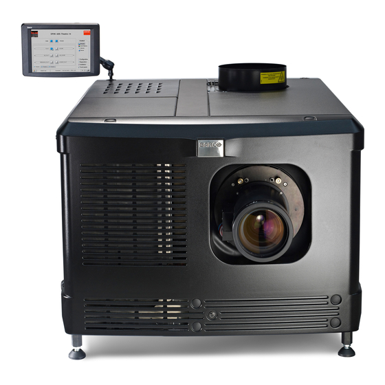
- Page 1 DPxK-32B User and Installation manual For DP2K-32B and DP4K-32B R59770491/08 17/09/2012...
- Page 2 Barco Inc. Media and Entertainment Division 11101 Trade Center Drive, Rancho Cordova, California 95670, USA Phone: +1 916 859-2500 Fax: +1 916 859-2515 Support: www.Barco.com/esupport Visit us at the web: www.barco.com Barco nv Entertainment Division Noordlaan 5, B-8520 Kuurne Phone: +32 56.36.82.11 Fax: +32 56.36.883.86...
- Page 3 Changes Barco provides this manual ’as is’ without warranty of any kind, either expressed or implied, including but not limited to the implied war- ranties or merchantability and fitness for a particular purpose. Barco may make improvements and/or changes to the product(s) and/or the program(s) described in this publication at any time without notice.
- Page 4 GNU-GPL code If you would like a copy of the GPL source code contained in this product shipped to you on CD, please contact Barco. The cost of preparing and mailing a CD will be charged. Guarantee and Compensation Barco provides a guarantee relating to perfect manufacturing as part of the legally stipulated terms of guarantee. On receipt, the purchaser must immediately inspect all delivered goods for damage incurred during transport, as well as for material and manufacturing faults Barco must be informed immediately in writing of any complaints.
- Page 5 中国大陆 RoHS 根据中国大陆 《电子信息产品污染控制管理办法》( 也称为中国大陆 RoHS),以下部份列出了本产品中可能包含的有毒有害物质或元素 的名称 和含量。 Projector 零部件名稱 有毒有害物質或元素 铅(Pb) 镉(Cd 多 溴 二 苯 醚 汞(Hg) 六价铬(Cr6+) 多溴联苯(PBB) (PBDE) 金屬機構件 塑膠機構件 电路板组件* 燈泡 電源模組 电源线 外部信号连接线 風扇 散熱模組 (金屬部 分) 讀卡器 喇叭 (電路板組件 除外) 附電池遙控器 (電 路板組件除外) *:...
-
Page 7: Table Of Contents
Table of contents TABLE OF CONTENTS 1. Safety ....................... .. 3 General considerations. - Page 8 Table of contents 11.3 Cleaning the lens ........................95 11.4 Cleaning the exterior of the projector .
-
Page 9: Safety
• Before operating this equipment please read this manual thoroughly and retain it for future reference. • Installation and preliminary adjustments should be performed by qualified Barco personnel or by authorized Barco service deal- ers. • All warnings on the projector and in the documentation manuals should be adhered to. -
Page 10: Important Safety Instructions
1. Safety Important safety instructions To prevent the risk of electrical shock • This projector should be operated from an AC power source. Ensure that the mains voltage and capacity matches the projector electrical ratings. If you are unable to install the AC requirements, contact your electrician. Do not defeat the purpose of the grounding. - Page 11 fire extinguishers. Never use water on an electrical fire. Always have service performed on this projector by authorized Barco service personnel. Always insist on genuine Barco replacement parts. Never use non-Barco replacement parts as they may degrade the safety of this projector.
- Page 12 If the product exhibits a distinct change in performance, indicating a need for service. • Replacement parts: When replacement parts are required, be sure the service technician has used original Barco replacement parts or authorized replacement parts which have the same characteristics as the Barco original part. Unauthorized substitu- tions may result in degraded performance and reliability, fire, electric shock or other hazards.
- Page 13 1. Safety AUTION Xenon compact arc lamps are highly pressurized. When ignited, the normal operating temperature of the bulb increases the pressure to a level at which the bulb may explode if not handled in strict accordance to the manufacturer’s instructions. The bulb is stable at room temperature, but may still explode if dropped or otherwise mishandled.
- Page 14 1. Safety R59770491 DPXK-32B 17/09/2012...
-
Page 15: General
Barco provides a guarantee relating to perfect manufacturing as part of the legally stipulated terms of guar- antee. Observing the specification mentioned in this chapter is critical for projector performance. Neglecting this can result in loss of warranty. -
Page 16: Unpacking The Projector
Projector weight Do not underestimate the weight of the Barco DPxK-32B. The projector weights about ±140 kg (±309 lb.) without lens. Be sure that the pedestal on which the projector has to be installed is capable of handling five (5) times the complete load of the system. - Page 17 2. General Image 2-1 Open banding 2. Open the box. Take out the small box between the outer and inner box containing the manuals. Remove the outer carton box Image 2-2 Remove outer carton 3. Remove the inner carton box. R59770491 DPXK-32B 17/09/2012...
- Page 18 2. General Image 2-3 Remove inner carton 4. Loosen the banding by pulling the free end of the banding loop in the clip. Take off the upper carton plate (1) Remove from the wooden pallet (2) Image 2-4 Remove wooden pallet 5.
-
Page 19: Initial Inspection
This check should confirm that there are no broken knobs or connectors, that the cabinet and panel surfaces are free of dents and scratches, and that the operating panel is not scratched or cracked. The Barco Sales and Service office should be notified as soon as possible if this is not the case. - Page 20 12.Registration of the projector. The DPxK-32B is DCI compliant and should be registered by Barco. Therefore, the digital certifi- cate inside the projector will be used to secure encryption key communication between the projector and the rest of the theatre system (server and theatre management system).
-
Page 21: Physical Installation
Image 3-1 Positioning at port window Barco offers a pedestal for the DPxK-32B digital projector. This universal pedestal allows a solid and easy setup of the projector. The universal pedestal has a separate compartment to install the UPS unit (if available) for the DPxK-32B digital projector. - Page 22 3. Physical installation 2. If a film projector is already present (projector will be off-center), try to optimize aim (see ref B image 3-2). Note: Unlike film projectors, it is best to keep the projector lens surface as parallel to the screen as possible, even if it is significantly above the screen center.
-
Page 23: Installation Of The Exhaust System
90° Inclined screen Image 3-4 Projector tilting Barco offers a pedestal for the DPxK-32B digital projector. This universal pedestal allows you to easily tilt the projector forward up to 6°. Installation of the exhaust system ARNING THE USE OF AN EXHAUST SYSTEM IS MANDATORY ! ARNING Never look into the exhaust output. - Page 24 3. Physical installation Image 3-5 Exhaust system Ensure good condition of the lamp house blower. Keep the blower inlet clean for unrestricted air flow. To ensure maximum lamp life, operate the lamp house blower and the exhaust system for at least ten minutes after extinguishing the lamp.
-
Page 25: Access To The Power Connection
3. Physical installation Image 3-6 Fan power connection Access to the power connection Necessary tools Flat screw driver 6 mm How to access 1. Remove the back cover. 2. Loosen both captive screws (1). Image 3-7 Power connection cover, captive screws 3. -
Page 26: Power Input Setup Of The Dpxk-32B
3. Physical installation Image 3-8 The terminal barrier strip and Ү/Δ configuration block is accessible. Power input setup of the DPxK-32B About the power input The projector power input can be configured for a power supply of 230/400V 3W+N+PE (Υ-connection) or for 208V 3W+PE (Δ-con- nection). -
Page 27: Connecting The Dpxk-32B With The Power Net
3. Physical installation Δ Image 3-10 Υ to Δ connection 2. Take off the mounted lins (A, B and C). Two links above each other or mounted between the upper and middle pin (A, B) and one link between the middle pin and lower pin (C). 3. - Page 28 3. Physical installation Necessary tools • Flat torque screw driver 4 mm • Adjustable wrench Necessary parts • (for 3W+N+PE, 230/400V) Certified power cable, minimum 4 mm² or AWG 10, 500V rated, cable diameter between 11 mm and 21 mm or •...
-
Page 29: Power Loop Through To The Projector Electronics
How to loop through the power 1. Plug in the short power cable (1) which was delivered with the projector. Warning: Always use the Barco short power cable which is delivered with the projector. Image 3-14 Power loop through connection 2. - Page 30 3. Physical installation Connect directly (A) or drag the cable behind the front cover so that the front cover can be removed without removing the UPS INLET cable (B). Image 3-15 UPS connection 3. Secure the UPS inlet socket with a fixation spring. Handle as follow: Squeeze the fixation spring together.
-
Page 31: Lamp & Lamp House
4. Lamp & Lamp House 4. LAMP & LAMP HOUSE About this chapter This chapter describes how to insert a lamp house in the projector and how to replace a lamp inside the lamp house and that for a motorized lamp house as for a non motorized lamp house. ARNING DO NOT PERMIT UNAUTHORIZED PERSONNEL TO PERFORM OR ATTEMPT ANY PHASE OF XENON LAMP HANDLING OR SERVICE. - Page 32 4. Lamp & Lamp House Image 4-1 Left: Xenon lamp wrapped in a protective cloth. Right: Xenon lamp captured in a protective container. AUTION Xenon compact arc lamps are highly pressurized. When ignited, the normal operating temperature of the bulb increases the pressure to a level at which the bulb may explode if not handled in strict accordance to the manufacturer’s instructions.
-
Page 33: Supported Xenon Lamps For The Xl Lamp House
Supported lamp types and their respective anode/cathode adapters for the XL Lamp House: Anode adapter Anode adaptation Lamp type / Cathode adapter Barco Order No. bushing Supplier R8436061K R859987K R9855950 3000W DHS OFR... -
Page 34: Removal Of The Lamp House
R859984K R8436111K R8436061K Image 4-5 The shortest cathode adapter R8436101K is no longer needed for xenon lamps supported by Barco. For that this adapter has become obsolete. Removal of the Lamp House ARNING This procedure may only be performed by qualified technical service personnel. -
Page 35: Removal Of The Xenon Lamp From Manual Xl Lamp House
4. Lamp & Lamp House a) Grip the Lamp House by the bottom handle and partially slide it out of the lamp compartment b) Grip the Lamp House by both handles and remove it completely from the projector. c) Place the Lamp House on a stable support. Caution: Be aware of the weight of the lamp assembly. - Page 36 4. Lamp & Lamp House ARNING Always wear clean leather gloves with wrist protectors when handling xenon lamps. Necessary tools • Two open-end wrenches of 22mm. • 5mm Allen wrench. • Lamp protective container or protective cloth with two binders. •...
- Page 37 4. Lamp & Lamp House Image 4-9 4. Support the xenon lamp inside the Lamp House with one hand while removing the UV blocker assembly from the lamp house. Supporting the xenon lamp with one hand to prevents it from bumping against the chassis of the Lamp House. Warning: Image 4-10 5.
- Page 38 4. Lamp & Lamp House Image 4-12 7. Place the xenon lamp in its protective container or wrap the xenon lamp in a protective cloth and secure with two binders. Image 4-13 Left: Xenon lamp wrapped in a protective cloth. Right: Xenon lamp captured in a protective container. 8.
-
Page 39: Installation Of The Xenon Lamp In Manual Xl Lamp House
4. Lamp & Lamp House Image 4-15 10.Remove the anode adapter from the xenon lamp by releasing the hexagon socket head set screw (reference 13 image 4-16) of the lamp adapter as illustrated. Use for that a 2.5mm Allen wrench. Image 4-16 Reinstall the UV blocker assembly and the side cover in case you do not intend to install another xenon lamp immediately in the Lamp House. - Page 40 4. Lamp & Lamp House ARNING This procedure may only be performed by qualified technical service personnel. AUTION Xenon compact arc lamps are highly pressurized. When ignited, the normal operating temperature of the bulb increases the pressure to a level at which the bulb may explode if not handled in strict accordance to the manufacturer’s instructions.
- Page 41 4. Lamp & Lamp House 2. Requires the xenon lamp an anode adapter? Tip: See supported xenon bulb lamps to know if your lamp requires an anode adapter. If yes, install the appropriate lamp anode adapter on the anode of the xenon lamp. Fasten the set screw (reference 13 image 4-18) of the anode adapter with a torque of 2.5Nm (1.84 lbf*ft).
- Page 42 4. Lamp & Lamp House 25 Nm Image 4-20 5. Check the cathode connection inside the lamp house. Use an 22 mm open-end wrench to hold the first nut while fastening the second nut on the rod with a torque of 25Nm (18.4 lbf*ft) using a torque wrench with 22 mm hexagon socket. Ensure that there is a flat washer at both sides of the wire lug.
- Page 43 4. Lamp & Lamp House Image 4-22 8. Slide the anode connector in its position on the Lamp House as illustrated. Caution: Avoid any tension on the anode wire, so there is no mechanical stress on the lamp. Image 4-23 9.
- Page 44 4. Lamp & Lamp House Image 4-25 11. Install the side cover of the Lamp House and fasten the three quarter turn screws (reference 4 image 4-26) of the cover. Note: Please ensure that the quarter turn screws turning wires are flush with the cover or interference will occur while inserting the Lamp House into the projector.
-
Page 45: Check If Anode Support Must Be Provided With A Plain Washer
4. Lamp & Lamp House A realignment of the xenon lamp in its reflector is required after the installation of the xenon lamp in the Lamp House. Check if anode support must be provided with a plain washer Necessary tools •... -
Page 46: Installation Of The Lamp House
4. Lamp & Lamp House Image 4-29 Installation of the Lamp House ARNING This procedure may only be performed by qualified technical service personnel. AUTION Due to its high internal pressure, the lamp may explode in either hot or cold states if improperly handled. -
Page 47: Resetting The Lamp Parameters
4. Lamp & Lamp House 3. Push the Lamp House fully into the slots. 4. Secure the Lamp House by fastening the two retaining screws (reference 1 image 4-31) at the base of the Lamp House. 5. Reinstall the cover of the Lamp House compartment. Image 4-31 Resetting the lamp parameters AUTION... - Page 48 4. Lamp & Lamp House Image 4-32 Reset lamp info, new lamp A Reset lamp parameters selection window opens (2). 2. To get new lamps, click on From new list (3). The lamp article and serial number opens (4). 3. Fill out the article number of the new lamp (5a) click on Select (5b) to display a list of possible article numbers (6).
- Page 49 4. Lamp & Lamp House Image 4-33 Reset lamp info, used lamp A Reset lamp parameters window opens (2). 2. To get history of the used lamps, click from history (3). The Reset lamp history selection window opens (4). 3. Click on Select (5) to display a list of possible lamps (6). 4.
-
Page 50: Realignment Of The Lamp In Its Reflector (Manual Lamp House)
4. Lamp & Lamp House 5. The lamp parameters can be edited by the user under personnel maintenance and responsibility. If you want to change these parameters, check the check box in front of Edit lamp parameters (11). The current parameter fields become active (12). 6. - Page 51 4. Lamp & Lamp House Image 4-35 Realignment points 6. Switch of the projector. 7. Reinstall the lamp cover. R59770491 DPXK-32B 17/09/2012...
- Page 52 4. Lamp & Lamp House R59770491 DPXK-32B 17/09/2012...
-
Page 53: Lenses & Lens Holder
• Scheimpflug adjustment Available lenses Which lenses are available for my projector? The table below is subject to changes and was last updated on 01/06/2012. Consult my.barco.com for the most recent information about available lenses. Product Number 2K zoom range... - Page 54 5. Lenses & lens holder Image 5-1 Image 5-2 Image 5-3 R9855958 R9855942 R9855943 Image 5-4 Image 5-5 Image 5-6 R9855963 R9855945 R9855964 Image 5-7 Image 5-8 Image 5-9 R9855946 R9855947 R9856294 Image 5-10 Image 5-11 R9856297 R9856300 R59770491 DPXK-32B 17/09/2012...
-
Page 55: Lens Selection
2. Login on my.barco.com. If you are not yet registered click on Sign up for my.barco.com and follow the instructions. With the created login and password, it is possible to enter the my.barco.com. When your login is correct, the my.barco.com start page is displayed. - Page 56 5. Lenses & lens holder 3. Place the lens holder in the “unlocked” position by moving the lens lock handle (1) towards the lens power supply socket (2). Image 5-13 Unlock lens holder 4. Ensure that the lens holder stands in the On-Axis position (horizontal and vertical mid position). Note: The lens holder is placed default in the On-Axis position at factory.
-
Page 57: Lens Removal
5. Lenses & lens holder Image 5-15 Fix lens AUTION Never transport the projector with a Lens mounted in the Lens Holder. Always remove the Lens before transporting the projector. Neglecting this can damage the Lens Holder and Prism. Lens removal How to remove a lens? 1. -
Page 58: Lens Shift, Zoom & Focus
5. Lenses & lens holder Image 5-17 Remove lens It’s recommended to place the Lens caps of the original Lens packaging, back on both sides of the removed Lens to protect the optics of the Lens. It’s recommended to place the foam rubber of the original projector packaging, back in the Lens opening to prevent intrusion of dust. -
Page 59: Scheimpflug Adjustment
5. Lenses & lens holder Image 5-19 If no, use the zoom barrel on the lens to zoom in or out. How to focus? 1. Use the “+” and “-” focus keys on the local keypad to focus the image on the screen. Image 5-20 Scheimpflug adjustment What has to be done ? - Page 60 5. Lenses & lens holder Scheimpflug adjustment points Image 5-22 Scheimpflug adjustments Indication on drawing Function Locking nut 1, 2 and 3 Scheimpflug adjustment nuts A, B, C and D Set screws a, b, c and d lock nuts 1, 2 and 3 are adjustment points. 4 is a locking point and NOT used during Scheimpflug adjustment.
- Page 61 5. Lenses & lens holder Image 5-24 Center focusing 6. Sharpen bottom left corner of the screen by adjusting nut 1. Image 5-25 Left bottom focusing 7. Sharpen bottom right corner of the screen by adjusting nut 2. R59770491 DPXK-32B 17/09/2012...
- Page 62 5. Lenses & lens holder Image 5-26 Right bottom focusing 8. Sharpen top right corner of the screen by adjusting nut 3 Image 5-27 Corner focusing 9. Repeat from step 6 until the projected focus pattern is as sharp as possible in the center, left, right, top and bottom of the screen. How to fix the Scheimpflug Start the fixation as follows (steps must be followed strictly) : 1.
- Page 63 5. Lenses & lens holder 1/3 to 1/2 Image 5-28 4. Fasten lock nut d. 5. Tighten nut 4 until the offset of the image movement created in step 3 is canceled. Tip: The amount of image movement in step 3 will determine how tight the nut in step 5 will need to be turned to return the image to its original position R59770491 DPXK-32B 17/09/2012...
- Page 64 5. Lenses & lens holder R59770491 DPXK-32B 17/09/2012...
-
Page 65: Input & Communication
6. Input & communication 6. INPUT & COMMUNICATION Overview • Introduction • Local keypad of the DPxK-32B • Communication ports of the DPxK-32B • Source input ports of the DPxK-32B • LED indications on the Integrated Cinema Processor module Introduction General The input &... -
Page 66: Local Keypad Of The Dpxk-32B
6. Input & communication Local keypad of the DPxK-32B Identification of the keys Image 6-2 Local keypad Marker area for macro name Numeric keyboard Standby key Dowser open/close switch Test pattern toggle switch Lens shift up/down, left/right Lens focus Lens zoom Numeric keys All the numeric keys (2) of the local keypad have a blue backlight during normal operation. -
Page 67: Communication Ports Of The Dpxk-32B
6. Input & communication Communication ports of the DPxK-32B Location of the communication ports STAT STAT STAT STAT CINEMA CONT POWER SMPTE 292/424 IN SYNC OK SYNC OK RS232 IN 3D INTERFACE PERIPHERAL PORT 10 / 100 / 1000 BASE-T DVI INPUT GENERAL PURPOSE IN/OUT DVI A... -
Page 68: Source Input Ports Of The Dpxk-32B
6. Input & communication Can be used to connect external 3D devices to the projector. All signals necessary for 3D projection can be provided via this con- nector. PERIPHERAL PORT For future use. Source input ports of the DPxK-32B Location of the source input ports STAT STAT STAT... -
Page 69: Led Indications On The Integrated Cinema Processor Module
6. Input & communication Input Source Vertical rate Scan type Color space Sampling Color depth standard Single DVI VESA (640x480) 72 Progressive 4:4:4 8 bit Single DVI VESA (800x600) 60 Progressive 4:4:4 8 bit Single DVI VESA (800x600) 72 Progressive 4:4:4 8 bit Progressive... - Page 70 6. Input & communication ALTERNATIVE port selection. When on, LED 6 will be out. USB, for future use. R59770491 DPXK-32B 17/09/2012...
-
Page 71: Communicator Touch Panel
7. Communicator Touch Panel 7. COMMUNICATOR TOUCH PANEL Overview • Introduction • Installation of the touch panel interface Introduction Communicator Touch Panel for digital cinema projectors The Communicator Touch Panel is designed for multi-user command and control, the Communicator enables users to learn quickly and operate efficiently - using an elegant and flexible touch panel interface. -
Page 72: Installation Of The Touch Panel Interface
7. Communicator Touch Panel Touch screen Communication panel Knob to operate central swivel clamp Base of swivel arm Power input 12 VDC, 1.5A RS232 port (sub-D) Ethernet port (RJ45) AUTION For more information about the use of the Communicator Touch Panel, consult its user guide. Installation of the touch panel interface Necessary tools •... - Page 73 7. Communicator Touch Panel Image 7-5 Touch panel mounted Image 7-4 Mount touch panel 3. Place the touch panel interface on the mounting plate of the swivel arm and fasten the two wing nuts (W) as illustrated. Image 7-6 Mount touch panel 4.
- Page 74 7. Communicator Touch Panel Image 7-8 Connections R59770491 DPXK-32B 17/09/2012...
-
Page 75: Starting Up
8. Starting up 8. STARTING UP About this chapter This chapter contains the switch ON and switch OFF procedures of the DPxK-32B. These procedures enumerate all the important points which have to be checked prior to switching ON the projector. This is to ensure a safe start up of the projector. Overview •... - Page 76 8. Starting up R59770491 DPXK-32B 17/09/2012...
-
Page 77: Projector Registration
Overview The current projector is DCI compliant and should be registered by Barco. Therefore, the digital certificate inside the projector will be used to secure encryption key communication between the projector and the rest of the theatre system (server and theatre man- agement system). -
Page 78: Registration Of New Projector
The procedure below gives an overview of all possible steps which can be displayed. How to register 1. Go to Barco’s Partnerzone on https://my.barco.com. 2. Login into the partnerzone. If you are not yet registered, click on Sign in here and follow the instructions. With the created login and password, it is possible to enter the partnerzone where you can upload the certificate. - Page 79 9. Projector registration Image 9-3 Lenses: click on the drop down box and select the lens of the projector when a M25 lens or select Other lens when no M25 lens is used. When other lens is selected, an extra input field appears to fill out the lens type. Anamorphic lens: check when an anamorphic lens is available.
- Page 80 9. Projector registration If the location is not in the list, click Add new and continue to next step. 7. Fill out all fields with an asterisk for Location, Contact person and Support contact. Click Next >>. Image 9-5 Add new location The new location is added to the list of locations and is selected.
- Page 81 9. Projector registration Image 9-7 Add new installer The new installer is added to the list of installers and is selected. Click Next >> to continue to next step. The owner input form appears. 10.If the owner is in the list, select the owner and click Next >> to finalize the registration. If the owner is not in the list, click Add new and continue with next step.
- Page 82 9. Projector registration Image 9-9 Add new owner The new owner is added to the list of owners and is selected. Click Next >> to finalize the registration. The registration is completed. An E-mail will be sent to the person who is logged in. R59770491 DPXK-32B 17/09/2012...
-
Page 83: Update Registration Of An Existing Projector
How to update 1. First get a new certificate file. See "Download the certificate file", page 71. 2. Go to Barco’s Partnerzone on https://secure.barco.com/digitalcinema/. 3. Login into the partnerzone. Click Register DC projector and select Update DC projector. - Page 84 9. Projector registration The update page is displayed with your registered projectors. Image 9-11 Select projector to update 4. Select the projector for which the registration must be updated. The installation address is displayed in Selection Click >> Next to continue. 5.
-
Page 85: Removal And Installation Of The Projector Covers
10. Removal and installation of the projector covers 10. REMOVAL AND INSTALLATION OF THE PROJECTOR COVERS ARNING All procedures in this chapter may only be performed by “qualified service technicians” . ARNING Disconnect the power to the circuit mains terminals and unplug the power cord at UPS INLET, unless otherwise specified in the procedure. -
Page 86: Removal Of The Lamp Cover
10. Removal and installation of the projector covers 10.1 Removal of the lamp cover Necessary tools Flat screwdriver How to remove 1. Release both captive screws on top of the lamp cover. Image 10-2 Lamp cover, fasting screws 2. Push both lock to each other to release the locks and pull at the same time the bottom side of the cover away form the projector. Image 10-3 Lamp cover, locks 3. -
Page 87: Removal Of The Rear Cover
10. Removal and installation of the projector covers Image 10-4 Lamp cover, removal 10.2 Removal of the rear cover Necessary tools Flat screwdriver How to remove 1. Release both captive screws almost at the bottom of the rear cover using a flat screw driver (1). R59770491 DPXK-32B 17/09/2012... -
Page 88: Removal Of The Input Cover
10. Removal and installation of the projector covers Image 10-5 Rear housing removal 2. Remove the rear cover of the projector doing the following: a) gently pull out the top covers of the rear cover (2). b) then move the rear cover away from the projector. 10.3 Removal of the input cover Necessary tools Flat screwdriver... - Page 89 10. Removal and installation of the projector covers Image 10-6 Input cover, fixation 2. Remove the input cover as follow: a) Pull the bottom side of the cover to you until the cover is unlocked. b) Slide the full cover away from the projector. R59770491 DPXK-32B 17/09/2012...
-
Page 90: Removal Of The
10. Removal and installation of the projector covers Image 10-7 Input cover removal 10.4 Removal of the front cover Necessary tools Flat screwdriver How to remove 1. Check if the lens is removed. 2. Remove the rubber dust ring from the lens holder. R59770491 DPXK-32B 17/09/2012... - Page 91 10. Removal and installation of the projector covers Image 10-8 Release cover removal 3. Release the captive screw at the middle bottom of the front cover. 4. Remove the front cover as follow: a) standing in front of the projector, pull the top side of the cover to you until it is unlocked. b) slide the cover away from the projector.
-
Page 92: Removal Of The Side Cover
10. Removal and installation of the projector covers 10.5 Removal of the side cover Necessary tools Flat screwdriver How to remove 1. Release both captive screws on top of the side cover. Image 10-10 Captive screws 2. Push both lock to each other to release the locks and pull at the same time the bottom side of the cover away form the projector. Image 10-11 Unlock side cover 3. -
Page 93: Installation Of The
10. Removal and installation of the projector covers Image 10-12 Side cover 10.6 Installation of the front cover Necessary tools Flat screwdriver How to install 1. Ensure that no lens is mounted. 2. Execute the next steps to install the front cover: a) Hook the bottom side of the cover to the projector. -
Page 94: Installation Of The Input Cover
10. Removal and installation of the projector covers Image 10-14 Secure front cover 4. Reinstall the rubber dust ring around the lens holder. 10.7 Installation of the input cover Necessary tools Flat screwdriver How to install 1. Place the top side of the cover on its place. Image 10-15 Mount input cover 2. -
Page 95: Installation Of The Lamp Cover
10. Removal and installation of the projector covers Image 10-16 Secure input cover 3. Secure the cover by fastening the captive screw. 10.8 Installation of the lamp cover Necessary tools Flat screwdriver How to install 1. Place the top side of the cover on its place. R59770491 DPXK-32B 17/09/2012... - Page 96 10. Removal and installation of the projector covers Image 10-17 Mount lamp cover Close the cover as follow: a) Gently move the bottom side of the cover towards the projector b) Push both lock to each other and push at the same time the cover against the projector frame. c) Release both locks so that they lock in their receivers.
-
Page 97: Installation Of The Rear Cover
10. Removal and installation of the projector covers 10.9 Installation of the rear cover Necessary tools Flat screwdriver How to install 1. Install the rear cover of the projector doing the following: a) Bring the rear cover towards its final position. b) Gently push the locking studs into the receivers (1). - Page 98 10. Removal and installation of the projector covers Image 10-20 2. Secure the cover by fasting both captive screws. Image 10-21 Lock side cover R59770491 DPXK-32B 17/09/2012...
-
Page 99: Maintenance
11. Maintenance 11. MAINTENANCE About this chapter This chapter describes how to remove the dust filters Overview • Remove and clean the front dust filter • Remove and clean both bottom dust filters • Cleaning the lens • Cleaning the exterior of the projector •... - Page 100 11. Maintenance Image 11-1 Front dust filter Clean the dust filter 1. Remove most contamination with a vacuum cleaner in an other room or outside. 2. Blow remaining dust away with compressed air in an other room or outside. Mount the dust filter 1.
-
Page 101: Remove And Clean Both Bottom Dust Filters
11. Maintenance 11.2 Remove and clean both bottom dust filters How to remove 1. Remove the side cover. 2. Slide out the bottom front dust filter. Image 11-3 Bottom front dust filter 3. Slide out the bottom back dust filter. Image 11-4 Bottom back dust filter Clean the dust filter... -
Page 102: Cleaning The Exterior Of The Projector
11. Maintenance 2. Wipe lenses in a one single direction. Warning: Do not wipe back and forwards across the lens surface as this tends to grind dirt into the coating. 3. Do not leave the cleaning cloth in either an open room or lab coat pocket, as doing so can contaminate the cloth. 4. -
Page 103: Cooling Liquid Refill
11. Maintenance 11.6 Cooling liquid refill ARNING This procedure may only be performed by qualified technical service personnel. Order info cooling liquid B1909086K : bottle of 1 liter cooling liquid. Necessary parts Cooling liquid How to refill 1. Remove the side cover, see "Removal of the side cover", page 86. 2. - Page 104 11. Maintenance Image 11-7 Keypad The color of the backlight of the numeric keys 1 to 6 of the local keypad changes from blue to yellow. 4. Enter pin code within 5 seconds. In case no keys are pressed, the color of the backlight of the numeric keys 1 to 6 changes back to blue. In case of an incorrect code entry, the color of the backlight of the numeric keys changes to red for 1 second and then back to blue.
-
Page 105: Convergence
12. Convergence 12. CONVERGENCE About this chapter This chapter describes how to prepare the projector for convergence adjustment and how to adjust the convergence. Overview • Open the sealed compartment • Close the sealed compartment • Convergence controls • Red on blue convergence •... -
Page 106: Close The Sealed Compartment
12. Convergence Image 12-2 Sealed cover, remove A security warning will be displayed on the projector. Execute the procedure “Authorization to clear security warning on the projector”. 12.2 Close the sealed compartment Necessary tools 3 mm Allen wrench How to close the sealed compartment 1. -
Page 107: Convergence Controls
12. Convergence Image 12-4 Sealed cover, fixation 12.3 Convergence controls Definitions-Abbreviations • X: Horizontal direction on the screen, with origin in the centre of the screen and + to the right • Y: Vertical direction on the screen, with origin in the centre of the screen and + to the top •... -
Page 108: Red On Blue Convergence
12. Convergence Convergence Test pattern For the manual correction of the DMD convergence, a typical convergence test pattern is generated. For a 4K projector, use the 4K test pattern. Image 12-6 Convergence test pattern Work Instructions: • GREEN and RED DMD’s are to be adjusted with reference to the BLUE dmd. •... -
Page 109: Green On Blue Convergence
12. Convergence 4. To translate RED horizontally in the X - direction, turn [3] anti-clockwise. 5. For clockwise rotations of RED, turning [1] anti-clockwise would generally suffice. If much rotation is required, [2] may also be turned in the opposite direction. Slight corrections to Y may be required after rotation. 6. - Page 110 12. Convergence Green Image 12-8 Green on blue convergence R59770491 DPXK-32B 17/09/2012...
-
Page 111: Specifications
A. Specifications A. SPECIFICATIONS About this chapter This chapter gives an overview of the specification of the projector as well as the dimensions, the center of gravity and the dimensions of the optional pedestal. Overview • Specifications of the DP2K-32B •... -
Page 112: Specifications Of The Dp4K-32B
A. Specifications A.2 Specifications of the DP4K-32B Overview Digital MicroMirror Device™ 3 x 1.38" DC4K dark metal devices Native resolution 4,096 x 2,160 pixels Housing Hermetically sealed DMDs and optical assembly Lamp 3kW - 7kW (Xenon lamp) Light Output 33,000 lumens (6.5 kW lamp) Screen size Up to 32m / 105 ft wide Contrast ratio... -
Page 113: Dimensions Of The Dpxk-32B
A. Specifications A.3 Dimensions of the DPxK-32B Overview Dimensions are given mm. 207.5 37.5 41.5 381.5 min. 31 Image A-1 Dimensions in mm R59770491 DPXK-32B 17/09/2012... -
Page 114: Dimensions Of The Universal Pedestal
A. Specifications A.4 Dimensions of the universal pedestal Dimensions 876,3 Image A-2 Dimensions given in millimeters. R59770491 DPXK-32B 17/09/2012... -
Page 115: Pin Configurations
B. Pin configurations B. PIN CONFIGURATIONS Overview • About General Purpose Inputs & Outputs (GPIO) • Pin configurations of the communication ports • Pin configurations of the inputs B.1 About General Purpose Inputs & Outputs (GPIO) General Purpose inputs Eight (8) opto-isolated general purpose inputs are available. These inputs are used to trigger the execution of macro files. For more explanation about the association of a macro to a GPI, consult the user guide of the Communicator touch panel. -
Page 116: Pin Configurations Of The Communication Ports
B. Pin configurations • Generate Falling Edge – generate a falling edge on the external GPO port if the present state of the output is high. If the present state of the external GPO is low, no edge will be generated. •... -
Page 117: Pin Configurations Of The Inputs
B. Pin configurations General Purpose In/Out GPOUT 8 P GPOUT 8 N reserved reserved reserved reserved reserved Ethernet port 10/100 Base-T — RJ45 port 1000 Base-T — RJ45 port Pair Color Description Description white/green TXD+ TX0+ green TXD- TX0- white/orange RXD+ RX0+ —... - Page 118 B. Pin configurations R59770491 DPXK-32B 17/09/2012...
-
Page 119: Index
Index INDEX Access power connection Focus Adaptation bushing Adapters Anode Adaptors General Cathode General considerations Anode support General Purpose I/O Plain washer GPIO USHIO Authorization Security warning Clear Important safety instructions Initial inspection Input Input & communication 59–63 Certificate file Communication ports Download Introduction... - Page 120 Index Lamp Restricted access Maintenance Mechanical check Safety 3–7 Battery explosion Notice on safety Electrical shock Fire hazard Personal injury Projector damage Owner’s record Servicing Scheimpflug Sealed compartment 99–100 Close Open Pedestal Dimensions Shift Physical installation Source input ports Specifications 105–106 Pin configuration 110–111...
- Page 121 Revision Sheet Barco nv Entertainment Division/Documentation Noordlaan 5, B-8520 Kuurne Phone: +32 56.36.82.11, Fax: +32 56.36.88.24 Support: www.Barco.com/esupport, Web: www.barco.com From: Date: Please correct the following points in this documentation (R59770491/08): page wrong correct R59770491 DP K-32B 17/09/2012...
Need help?
Do you have a question about the DP K-32B Series and is the answer not in the manual?
Questions and answers