Table of Contents
Advertisement
Quick Links
Advertisement
Table of Contents

Related Manuals for ICP DAS USA I-2533CS-FD


Summary of Contents for ICP DAS USA I-2533CS-FD
- Page 1 I-2533CS-FD User Manual Version 1.1.0, Jan. 2021 Service and usage information for I-2533CS-FD I-2533CS-FD ( CAN/CAN FD to Single-mode Fiber Bridge ) User Manual (version 1.1.0) Page: 1 Copyright © 2020 ICP DAS Co., Ltd. All Rights Reserved. E-mail: service@icpdas.com...
- Page 2 If you have any problem, please feel free to contact us. You can count on us for quick response. Email: service@icpdas.com I-2533CS-FD ( CAN/CAN FD to Single-mode Fiber Bridge ) User Manual (version 1.1.0) Page: 2 Copyright © 2020 ICP DAS Co., Ltd. All Rights Reserved. E-mail: service@icpdas.com...
-
Page 3: Table Of Contents
Revision History ..................40 6.2. Dimension ....................41 6.3. CAN Status Register ................. 42 I-2533CS-FD ( CAN/CAN FD to Single-mode Fiber Bridge ) User Manual (version 1.1.0) Page: 3 Copyright © 2020 ICP DAS Co., Ltd. All Rights Reserved. E-mail: service@icpdas.com... - Page 4 6.4. CAN Error Counter Register ..............43 I-2533CS-FD ( CAN/CAN FD to Single-mode Fiber Bridge ) User Manual (version 1.1.0) Page: 4 Copyright © 2020 ICP DAS Co., Ltd. All Rights Reserved. E-mail: service@icpdas.com...
-
Page 5: Introduction
CAN/CAN FD message filter. When users use the I-2533CS-FD on two CAN/CAN FD network with different CAN baud rate, it may be useful to reduce the bus loading of the network which has low baud rate. - Page 6 I-2533CS-FD ( CAN/CAN FD to Single-mode Fiber Bridge ) User Manual (version 1.1.0) Page: 6 Copyright © 2020 ICP DAS Co., Ltd. All Rights Reserved. E-mail: service@icpdas.com...
-
Page 7: Specifications
1 x USB (Mini-B) Compatibility USB 2.0 High Speed (480Mbps) Software Driver Built-in Windows 7/8.1/10 I-2533CS-FD ( CAN/CAN FD to Single-mode Fiber Bridge ) User Manual (version 1.1.0) Page: 7 Copyright © 2020 ICP DAS Co., Ltd. All Rights Reserved. E-mail: service@icpdas.com... - Page 8 Operating Temp. -30 ~ 80 ℃ Storage Temp. Humidity 10 ~ 90% RH, non-condensing I-2533CS-FD ( CAN/CAN FD to Single-mode Fiber Bridge ) User Manual (version 1.1.0) Page: 8 Copyright © 2020 ICP DAS Co., Ltd. All Rights Reserved. E-mail: service@icpdas.com...
-
Page 9: Features
Built-in switchable 120 ohm terminal resistor for CAN Bus Dip switch for CAN/CAN FD baud rate configuration I-2533CS-FD ( CAN/CAN FD to Single-mode Fiber Bridge ) User Manual (version 1.1.0) Page: 9 Copyright © 2020 ICP DAS Co., Ltd. All Rights Reserved. E-mail: service@icpdas.com... -
Page 10: Technical Data
The following figure is the block diagram illustrating the functions of the I-2533CS-FD. Figure 2-1-1 Block Diagram of I-2533CS-FD I-2533CS-FD ( CAN/CAN FD to Single-mode Fiber Bridge ) User Manual (version 1.1.0) Page: 10 Copyright © 2020 ICP DAS Co., Ltd. All Rights Reserved. E-mail: service@icpdas.com... -
Page 11: Appearance
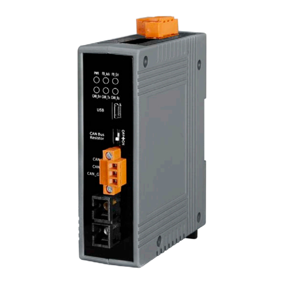
2.2. Appearance Figure 2-2-1 Appearance of I-2533CS-FD I-2533CS-FD ( CAN/CAN FD to Single-mode Fiber Bridge ) User Manual (version 1.1.0) Page: 11 Copyright © 2020 ICP DAS Co., Ltd. All Rights Reserved. E-mail: service@icpdas.com... -
Page 12: Pin Assignment
Power +Vs Voltage Source Input. +10V ~ +30V Power Ground. F.G. Frame Ground. I-2533CS-FD ( CAN/CAN FD to Single-mode Fiber Bridge ) User Manual (version 1.1.0) Page: 12 Copyright © 2020 ICP DAS Co., Ltd. All Rights Reserved. E-mail: service@icpdas.com... - Page 13 Wiring of CAN_GND and F.G. is not necessary; users can modify the configuration of wiring according to real applications. I-2533CS-FD ( CAN/CAN FD to Single-mode Fiber Bridge ) User Manual (version 1.1.0) Page: 13 Copyright © 2020 ICP DAS Co., Ltd. All Rights Reserved. E-mail: service@icpdas.com...
-
Page 14: 10-Pin Dip Switch
When users would like to set the CAN/CAN FD baud rate, module’s group id or update the firmware of the I-2533CS-FD, Users can use the 10-pin dip switch on the upper of the power connector to achieve these purposes. Users can find it on the top of the power connector. - Page 15 ■ Firmware Into firmware upgrade mode. upgrade mode OFF: Into normal operating mode. I-2533CS-FD ( CAN/CAN FD to Single-mode Fiber Bridge ) User Manual (version 1.1.0) Page: 15 Copyright © 2020 ICP DAS Co., Ltd. All Rights Reserved. E-mail: service@icpdas.com...
-
Page 16: Led Indicator
2.5. LED Indicator There are 6 LEDs on the I-2533CS-FD. One for power indication, two for fiber indication and three for CAN bus indication. The LED assignment and description are shown as follows. Figure 2-5-1 LED Assignment of I-2533CS-FD Table 2-5-1 LED Description... -
Page 17: Terminal Resistor Setup
The DIP switch for terminal resistor is on the upper of the CAN connector. Figure 2-6-2 Location of Terminal resistor DIP Switch I-2533CS-FD ( CAN/CAN FD to Single-mode Fiber Bridge ) User Manual (version 1.1.0) Page: 17 Copyright © 2020 ICP DAS Co., Ltd. All Rights Reserved. E-mail: service@icpdas.com... - Page 18 If your application is like the structure as follows, the terminal resistor is not needed. Figure 2-6-5 Application 2 I-2533CS-FD ( CAN/CAN FD to Single-mode Fiber Bridge ) User Manual (version 1.1.0) Page: 18 Copyright © 2020 ICP DAS Co., Ltd. All Rights Reserved. E-mail: service@icpdas.com...
-
Page 19: Module Group Id
2.7. Module Group ID The CAN port with the same “Group ID” setting can communicate with each other via fiber optics. This setting is used for I-2533CS-FD to communicate with the others modules on star topology application. Users can decide the value from 0 to 3 via pin 8 ~ 9 on 10-pin dip switch. The dip switch for “Group ID”... - Page 20 For example, there are three CAN networks, Network A, Network B and Network C, and each of them uses one I-2533CS-FD. The Group IDs of the I-2533CS-FDs are 1, 2, and 3 respectively. The Network A can exchange the data with Network C because the Group IDs of the I-2533CS-FDs are in the same group (the second rule in the above table).
-
Page 21: Wire Connection
The wire connection of the I-2533CS-FD is displayed below. Figure 2-8-1 Wire Connection for I-2533CS-FD I-2533CS-FD ( CAN/CAN FD to Single-mode Fiber Bridge ) User Manual (version 1.1.0) Page: 21 Copyright © 2020 ICP DAS Co., Ltd. All Rights Reserved. E-mail: service@icpdas.com... -
Page 22: Network Deployment
< 470 < 410 ~1.3 (AWG16) < 980 < 900 < 780 < 670 I-2533CS-FD ( CAN/CAN FD to Single-mode Fiber Bridge ) User Manual (version 1.1.0) Page: 22 Copyright © 2020 ICP DAS Co., Ltd. All Rights Reserved. E-mail: service@icpdas.com... -
Page 23: Fiber Selection & Fiber Length
3.2. Fiber Selection & Fiber Length The specification of fiber cable used to connect the I-2533CS-FD is shown as following table. Table 3-2-1 Specification of Fiber Diameter [μm] Operating Type (Core/Cladding) Wavelength [nm] 8.3/125, 8.7/125, Single mode 1310 9/125 or 10/125 The I-2533CS-FD allows maximum 30km fiber length for each kind of CAN baud theoretically. -
Page 24: Software Utility
After installing the .Net Framework components, the software will continue to install the Utility tool. 1. Click the “Next” button to continue. I-2533CS-FD ( CAN/CAN FD to Single-mode Fiber Bridge ) User Manual (version 1.1.0) Page: 24 Copyright © 2020 ICP DAS Co., Ltd. All Rights Reserved. E-mail: service@icpdas.com... - Page 25 2. Select the installation path of the I-2533CS-FD Utility and click the “Next” button. 3. Confirm the installation. Click the “Next” button to start the installation I-2533CS-FD ( CAN/CAN FD to Single-mode Fiber Bridge ) User Manual (version 1.1.0) Page: 25...
- Page 26 4. Installation complete. Click the “Close” button to exit I-2533CS-FD ( CAN/CAN FD to Single-mode Fiber Bridge ) User Manual (version 1.1.0) Page: 26 Copyright © 2020 ICP DAS Co., Ltd. All Rights Reserved. E-mail: service@icpdas.com...
-
Page 27: Setting Up The I-2533Cs-Fd
Utility and the I-2533CS-FD. Here is the example for the I-2533CS-FD configuration. Step 1: Connect the PC available USB port with the USB port of the I-2533CS-FD. Users can find the communication cable (CA-USB10) in the product box. -
Page 28: Start To Use I-2533Cs-Fd Utility Tool
[Advanced Settings] This field is used to configure the CAN ID filter of the module. I-2533CS-FD ( CAN/CAN FD to Single-mode Fiber Bridge ) User Manual (version 1.1.0) Page: 28 Copyright © 2020 ICP DAS Co., Ltd. All Rights Reserved. E-mail: service@icpdas.com... -
Page 29: Connect To The Module
4.3.1. Connect to the module Press the “Refresh” button to scan and list all the necessary I-2533CS-FD modules on “Module Name” location. Then select the necessary I-2533CS-FD module and press “Connect” button to start to connect with it. I-2533CS-FD ( CAN/CAN FD to Single-mode Fiber Bridge ) User Manual (version 1.1.0) Page: 29 Copyright ©... -
Page 30: Get Current Module Settings
“Data phase bit rate”: Current CAN FD data phase bit rate the I-2533CS-FD module used. I-2533CS-FD ( CAN/CAN FD to Single-mode Fiber Bridge ) User Manual (version 1.1.0) Page: 30 Copyright © 2020 ICP DAS Co., Ltd. All Rights Reserved. E-mail: service@icpdas.com... -
Page 31: Configure User-Defined Can Baudrate
CAN/CAN FD arbitration/data phase bit rate sample point. Suggested range: 75.00 ~ 87.50 % I-2533CS-FD ( CAN/CAN FD to Single-mode Fiber Bridge ) User Manual (version 1.1.0) Page: 31 Copyright © 2020 ICP DAS Co., Ltd. All Rights Reserved. E-mail: service@icpdas.com... -
Page 32: Configure Other Parameters
Both error counters are below the Error_Warning limit of 96 At least one of error counter has reached the Error_Warning limit of I-2533CS-FD ( CAN/CAN FD to Single-mode Fiber Bridge ) User Manual (version 1.1.0) Page: 32 Copyright © 2020 ICP DAS Co., Ltd. All Rights Reserved. E-mail: service@icpdas.com... - Page 33 CAN received CAN message frame per second. [Reset Module] command: Reset the module. I-2533CS-FD ( CAN/CAN FD to Single-mode Fiber Bridge ) User Manual (version 1.1.0) Page: 33 Copyright © 2020 ICP DAS Co., Ltd. All Rights Reserved. E-mail: service@icpdas.com...
-
Page 34: Configure Can Id Filter
4.3.5. Configure CAN ID Filter By using the I-2533CS-FD Utiltiy tool, user can configure the CAN ID filter of the module. The “Reject Remote Frame” is used to reject remote standard/extended CAN frame. And the “Standard ID/Extended ID” field are used to set accepted standard/extended CAN IDs. - Page 35 <7> “Clear Table” button: Delete all CAN IDs from “Standard/Extended ID Fiter” frame. I-2533CS-FD ( CAN/CAN FD to Single-mode Fiber Bridge ) User Manual (version 1.1.0) Page: 35 Copyright © 2020 ICP DAS Co., Ltd. All Rights Reserved. E-mail: service@icpdas.com...
-
Page 36: Firmware Upgrade
5. Firmware Upgrade Please refer to the following steps to upgrade the firmware of I-2533CS-FD module. Step 1: Power off the I-2533CS-FD. Step 2: Set the I-2533CS-FD’s pin 10 of 10-pin dip switch to ‘ON’ position. Switch 10-pin dip switch... - Page 37 Step 5: At this time, the I-2533CS-FD module will be simulated as a “USB Mass Storage Device”, and one more “USB Disk” window, will pop up on the PC side. Then users can upgrade the firmware of the I-2533CS-FD module via this USB disk.
- Page 38 Step 8: Select USB port and the necessary USB Disk of PC Step 9: Press the the “Browser…” button and select the firmware file (*.fw). I-2533CS-FD ( CAN/CAN FD to Single-mode Fiber Bridge ) User Manual (version 1.1.0) Page: 38...
- Page 39 Step 11: Set the 10-pin dip switch to the necessary position and reboot the module.Then press the “Exit” button to exit. I-2533CS-FD ( CAN/CAN FD to Single-mode Fiber Bridge ) User Manual (version 1.1.0) Page: 39 Copyright © 2020 ICP DAS Co., Ltd. All Rights Reserved. E-mail: service@icpdas.com...
-
Page 40: Appendix
Initial issue Upgrade CAN FD data bit rate to 10000 1.1.0 2021/01/25 kbps I-2533CS-FD ( CAN/CAN FD to Single-mode Fiber Bridge ) User Manual (version 1.1.0) Page: 40 Copyright © 2020 ICP DAS Co., Ltd. All Rights Reserved. E-mail: service@icpdas.com... -
Page 41: Dimension
6.2. Dimension I-2533CS-FD ( CAN/CAN FD to Single-mode Fiber Bridge ) User Manual (version 1.1.0) Page: 41 Copyright © 2020 ICP DAS Co., Ltd. All Rights Reserved. E-mail: service@icpdas.com... -
Page 42: Can Status Register
The CAN module is not in busoff state. The CAN controller is in busoff state. 31:8 Reserved I-2533CS-FD ( CAN/CAN FD to Single-mode Fiber Bridge ) User Manual (version 1.1.0) Page: 42 Copyright © 2020 ICP DAS Co., Ltd. All Rights Reserved. E-mail: service@icpdas.com... - Page 43 At error level. The receive counter has reached the error passive level of 128 31:16 Reserved I-2533CS-FD ( CAN/CAN FD to Single-mode Fiber Bridge ) User Manual (version 1.1.0) Page: 43 Copyright © 2020 ICP DAS Co., Ltd. All Rights Reserved. E-mail: service@icpdas.com...
Need help?
Do you have a question about the I-2533CS-FD and is the answer not in the manual?
Questions and answers