
Related Manuals for ICP DAS USA WF-2572M


Summary of Contents for ICP DAS USA WF-2572M
- Page 1 WF-2572/WF-2572M Ethernet to Wi-Fi Bridge User Manual v1.10 www.icpdas.com WF-2572 Series, Ethernet to Wi-Fi Bridge (V1.10, 2019/08/30) 1...
- Page 2 Technical Support _______________________________________________ If you have any problems, feel free to contact us via e-mail at service@icpdas.com Document Revision Version Date Note 1.00 2018/09/30 Release version 1.10 2018/08/30 Add WF-2572M of feature WF-2572 Series, Ethernet to Wi-Fi Bridge (V1.10, 2019/08/30) 2...
-
Page 3: Table Of Contents
HARDWARE ............................7 ............................7 PECIFICATIONS ........................ 8 WF-2572 S ERIES PPEARANCE Front Panel of WF-2572 ........................8 2.2.1 Front Panel of WF-2572M........................9 2.2.2 Top Panel ............................10 2.2.3 LED Indicator ........................... 11 2.2.4 ........................12 OWER WIRE CONNECTION ........................12... - Page 4 Test Architecture ..........................24 4.5.1 Setting step ............................24 4.5.2 TECHNICAL SUPPORT........................26 WF-2572 Series, Ethernet to Wi-Fi Bridge (V1.10, 2019/08/30) 4...
-
Page 5: Introduction
Wi-Fi to wire internet without complex settings. The WF- 2572/WF-2572M also supports dual bands (2.4/5 GHz). The 2.4 GHz is more crowded than 5 GHz. Therefore, the devices on 2.4 GHz suffer much more interference than the ones on 5 GHz. -
Page 6: Feature
Plug-and-Play Ethernet to Wi-Fi connectivity USB-based configuration No driver installation required Built-in Watchdog Metal case(WF-2572M) Extended operating temperature range (-25°C ~ +75°C) Utility Configuration by USB interface Support setting of Wi-Fi Infrastructure and Limit-AP mode Figure 1-2. -
Page 7: Hardware
2. Hardware 2.1 Specifications Item WF-2572 WF-2572M RF Specification Standard IEEE 802.11 a/b/g 2.4 GHz: CH1~11 Frequency 5 GHz: CH36、40、44、48 Operation mode Limit-AP / Infrastructure Encryption Open/WPA/WPA2 Omni-Directional Antenna 3 dBi @ 2.4 GHz 5.5 dBi @ 5 GHz Transmission Range... -
Page 8: Wf-2572 Series Appearance
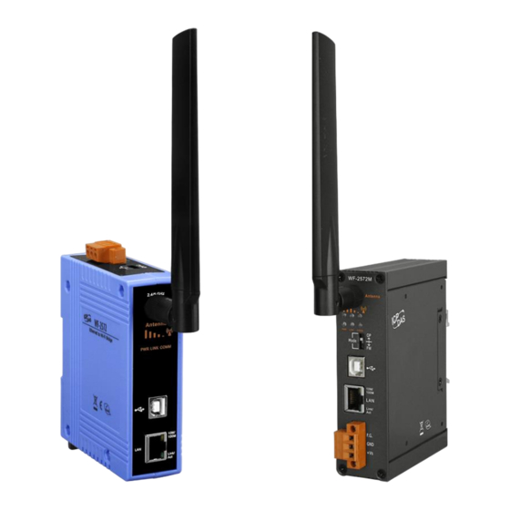
WF-2572 Series Appearance 2.2.1 Front Panel of WF-2572 The WF-2572 front panel contains the antenna, USB connector, Ethernet connector and LEDs. RP SMA Connector Signal Strength LED Indicator System Status LED Indicator USB/Ethernet Connector Figure 2-1. Front Panel of the WF-2572 WF-2572 Series, Ethernet to Wi-Fi Bridge (V1.10, 2019/08/30) 8... -
Page 9: Front Panel Of Wf-2572M
2.2.2Front Panel of WF-2572M The WF-2572M front panel contains the antenna, USB connector, Ethernet connector Power connector, operating mode selector switch and LEDs. RP SMA Connector Signal Strength LED Indicator System Status LED Indicator USB/Ethernet Connector Operating mode selector switch Power Connector Figure 2-2. -
Page 10: Top Panel
2.2.3 Top Panel The WF-2572 top panel contains the power connector and operating mode selector switch. FW mode: Firmware update mode OP mode: Firmware operation mode 11 Power Connector Operating mode selector switch Figure 2-3. Top Panel of WF-2572 Table 2-2. -
Page 11: Led Indicator
LED Indicator 2.2.4 The LED Indicator can be divided into two types. The one is signal strength indicator. The other is system status indicator. The description of the LED indicator as shown in Table 2-3. Table 2-3. The description of LED indicator LED Status Description Limit-AP mode... -
Page 12: Power Wire Connection
Power wire connection The power wire connection of WF-2572 has shown in Figure 2-4. Figure 2-4. Power wire connection of WF-2572 Watchdog Timer Setting A watchdog timer (WDT) is a device that performs a specific operation after a certain period of time if something goes wrong and the system does not recover on its own. A watchdog timer can perform a warm boot (restarting the system) after a certain number of milliseconds. - Page 13 can update the firmware of the WF-2572 via USB interface and it will become a “USB Mass Storage Device” and shows a folder automatically. Figure 2-6. FW update position of Dip-Switch Figure 2-7. USB Mass Storage Device Users just need to execute “Firmware_Update_Tool.exe” and follow the below steps to complete the firmware updating process.
-
Page 14: Firmware Operation Mode
The Firmware_Update_Tool can be downloaded from ftp://ftp.icpdas.com/pub/cd/usbcd/napdos/wifi/WF-2572/software/tool/ 2.5.2 Firmware Operation Mode As shown in Figure 2-9, Users need to set the dip-switch to the “OP” position and reset the power, which the WF-2572 can run in the operation mode. In this mode, user can use the WF- 2572 with a computer or other devices that have Ethernet interface for wireless connection. -
Page 15: Dimensions Of Wf-2572M
Figure 2-11. Top / Bottom side dimension of the WF-2572 2.6.2 Dimensions of WF-2572M Front View Left View Figure 2-12. Front / Left side dimension of the WF-2572M Right View Rear View Figure 2-13. Right / Rear side dimension of the WF-2572M... -
Page 16: Software
3. Software This chapter explains how to use the WF-2572 Utility to carry on the WF-2572 wireless communication configuration. 3.1 Wireless Configuration Tool – WF-2572 Utility WF-2572 utility is a Microsoft Windows application that compatibles with Microsoft Windows XP, 7 and 10. The WF-2572 Utility can be downloaded from ftp://ftp.icpdas.com/pub/cd/usbcd/napdos/wifi/wf-2572/software/utility/ 3.2 WF-2572 Utility... -
Page 17: Wi-Fi Parameter
3.3.1 Wi-Fi Parameter The Wi-Fi parameter can be divided into six types. The description of Wi-Fi parameter has shown in Table 3-1. Table 3-1. Description of Wi-Fi Parameter Wi-Fi Parameter Description Mode The Wi-Fi role of WF-2572. The Wi-Fi role consists of Station (Infrastructure) and AP (Limit-AP). -
Page 18: Ip Setting
Note: The PC and device must be in the same IP segment. Figure 3-2. device MAC search Figure 3-3 Success message 3.3.3 IP Setting The IP setting only support with the “Limit-AP” mode. Figure 3-4. Device IP Setting 4. Application Setting Users can use two WF-2572s or one WF-2572 module with the computer that supports wireless network connection structure in the application. -
Page 19: System Architecture Of Limit-Ap Mode
WF-2572 or other APs. The device can access Wi-Fi network after connecting to Wi-Fi AP. 2.4/5 GHz Ethernet Ethernet Wi-Fi AP WF-2572 Ethernet Device (Infrastructure mode) Ethernet Ethernet Ethernet Device WF-2572 WF-2572 (Limit-AP mode) (Infrastructure mode) Figure 4-1. System Architecture on Infrastructure Mode 4.2 System Architecture of Limit-AP Mode The system architecture of infrastructure mode shows in Figure 4-2. -
Page 20: Hardware Installation
4.3 Hardware Installation The associated hardware configuration is shown as following steps. Step1. Checking the WF-2572 operation mode It needs to set the DIP switch to the "OP" position (operating mode). As resetting the power, it will cause the device to operate in the operation mode. Figure 4-3 “OP”... -
Page 21: Setting Step
4.4.2 Setting step The WF-2572 has three steps. The setting step shows as following: Set WF-2572 to “Infrastructure” mode and Wi-Fi parameter Step1. 1. Change “Mode” to “Infrastructure” 2. Set AP SSID 3. Set authentication of Wi-Fi 4. Set password of Wi-Fi 5. -
Page 22: Query Device Mac By Using Wf-2572 Utility
Step3. Internet connection test ) + R will show you the “RUN” box where you can type commands 1. The Windows( to either pull up a program. The command line windows will be opening after typing “cmd” at the “RUN” box. 2. - Page 23 Figure 4-8. Computer’s MAC 2. Device: PLC or other Ethernet devices Step1. Connect the Ethernet cable between computer and PLC It needs to remove the Ethernet cable between device (PLC or other Ethernet devices) and WF-2572. After that, you can connect the Ethernet to the computer. Step2.
-
Page 24: Limit-Ap Mode
4.5 Limit-AP Mode 4.5.1 Test Architecture The test architecture has shown in Figure 4-10. Both of WF-2572 connects to the computer by Ethernet. One of the WF-2572 sets to the Limit-AP mode. The other WF-2572 sets to the Infrastructure mode. 2.4/5 GHz Ethernet Ethernet... - Page 25 Figure 4-11. Setting Wi-Fi Parameter Step2. The WF-2572’s Infrastructure setting can refer to chapter 4.4. Step3. Setting PC’s IP 1. As shown in Figure 4-12, the PC’s is “192.168.255.10” and “192.168.255.11”. Figure 4-12. Setting PC’s IP Step4. Internet Connection ) + R will show you the “RUN” box where you can type commands 1.
- Page 26 2. Please execute following command on the command line window. Command 1: ping 192.168.255.10 Command 2: ping 192.168.255.11 3. As shown in Figure 4-13, the internet access is working fine that it should show a similar reaction as following figures. Figure 4-13.
Need help?
Do you have a question about the WF-2572M and is the answer not in the manual?
Questions and answers