Advertisement
Quick Links
Packing List
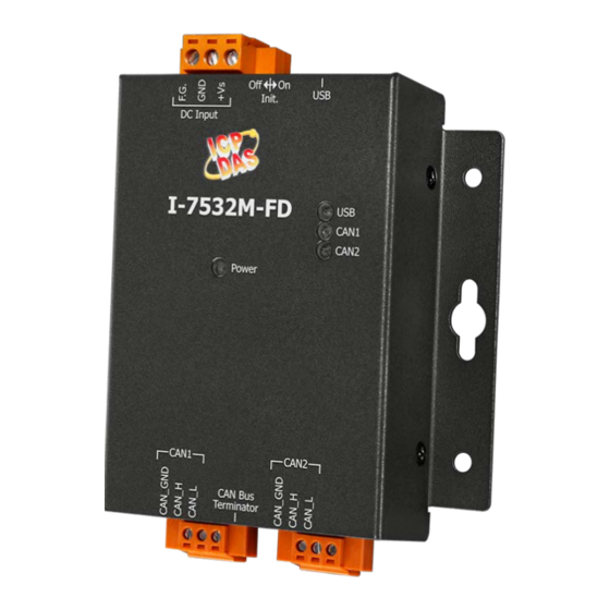
In addition to this guide, the package includes the following items:
I-7532M-FD
Technical Support
service@icpdas.com
www.icpdas.com
For Desktop Web
I-7532M-FD Quick Start
Screw Driver
Resources
How to search for drivers, manuals and
spec information on ICP DAS website.
For Mobile Web
Model Name
Model Name
v1.0, Oct 2020
USB Cable
(CA-USB10)
P1
Advertisement

Related Manuals for ICP DAS USA I-7532M-FD


Summary of Contents for ICP DAS USA I-7532M-FD
- Page 1 I-7532M-FD Quick Start v1.0, Oct 2020 Packing List In addition to this guide, the package includes the following items: USB Cable I-7532M-FD Screw Driver (CA-USB10) Resources How to search for drivers, manuals and Technical Support spec information on ICP DAS website.
-
Page 2: Hardware Installation
--------------------------------------------------------------------- Hardware Installation Before using I-7532M-FD device, some things must be done. Step 1: Prepare one I-7532M-FD Step 2: Determine if the terminal resistor is needed or not Check the application structure, and determine if the terminal resistor is needed or not. You can find it at the position as follows. - Page 3 Generally, if your application is as follows, we recommend you to enable the terminal resistor. If your application is like the structure as follows, the terminal resistor is not needed.
- Page 4 Step 3: Connect the CAN port, USB and power line of the I-7532M-FD. The pin assignment and wire connection are as follows. When finished, run your application with the I-7532M-FD.
-
Page 5: Utility Tool
Step 2: Setting up I-7532M-FD module 1. Connect the PC available USB port with the USB port of the I-7532M-FD. Users can find the communication cable (CA-USB10) in the product box. 2. Power On the module and execute the I-7532-FD Utility tool. - Page 6 Step 3: Connect and get module’s configuration Press the “Refresh” button to scan and list all the necessary I-7532M-FD modules on “Module Name” location. Then select the necessary I-7532M-FD module and press “Get Device Config.” button to start to connect and get device configuration.
- Page 7 [CAN Controller] Set the CAN port into CAN or CAN FD mode. When setting the CAN port into CAN FD mode, the CAN port can process CAN/CAN FD frames, otherwise this port just can process CAN frame. [CAN FD Spec.] Set the CAN FD frame of the CAN port follows ISO or Non-ISO specification.
- Page 8 Press the “Add”, “Delete” button to add/delete a range of standard/extended CAN ID into filter frame. Step 6: Setting CAN forwarding rules Detail information about how to configure CAN mapping, merging, splitting rules, please refer to section “3. Software Utility” of I-7532M-FD user’s manual.
Need help?
Do you have a question about the I-7532M-FD and is the answer not in the manual?
Questions and answers