Table of Contents
Advertisement
Quick Links
Advertisement
Table of Contents

Related Manuals for ICP DAS USA I-7532M-FD


Summary of Contents for ICP DAS USA I-7532M-FD
- Page 1 I-7532M-FD User Manual Version 1.0.0, Oct. 2020 Service and usage information for I-7532M-FD I-7532M-FD ( 2-port CAN/CAN FD Bridge ) User Manual (version 1.0.0) Page: 1 Copyright © 2020 ICP DAS Co., Ltd. All Rights Reserved. E-mail: service@icpdas.com...
- Page 2 If you have any problem, please feel free to contact us. You can count on us for quick response. Email: service@icpdas.com I-7532M-FD ( 2-port CAN/CAN FD Bridge ) User Manual (version 1.0.0) Page: 2 Copyright © 2020 ICP DAS Co., Ltd. All Rights Reserved. E-mail: service@icpdas.com...
-
Page 3: Table Of Contents
Firmware Upgrade ................... 43 Appendix ......................47 5.1. Revision History ..................47 5.2. Dimension ....................48 I-7532M-FD ( 2-port CAN/CAN FD Bridge ) User Manual (version 1.0.0) Page: 3 Copyright © 2020 ICP DAS Co., Ltd. All Rights Reserved. E-mail: service@icpdas.com... -
Page 4: Introduction
1. Introduction I-7532M-FD is a local CAN/CAN FD (CAN with Flexible Data-Rate) bridge used to establish a connection between two CAN/CAN FD networks. It can increase the bus loading capacity, extend communication distance, connect CAN/CAN FD networks with different baud rate and support messages transform between CAN and CAN FD networks. - Page 5 I-7532M-FD ( 2-port CAN/CAN FD Bridge ) User Manual (version 1.0.0) Page: 5 Copyright © 2020 ICP DAS Co., Ltd. All Rights Reserved. E-mail: service@icpdas.com...
-
Page 6: Specifications
-25 ~ 75 ℃ Operating Temp. -30 ~ 80 ℃ Storage Temp. Humidity 10 ~ 90% RH, non-condensing I-7532M-FD ( 2-port CAN/CAN FD Bridge ) User Manual (version 1.0.0) Page: 6 Copyright © 2020 ICP DAS Co., Ltd. All Rights Reserved. E-mail: service@icpdas.com... -
Page 7: Features
Messaging traffic of each port up to 10,000 fps. The baud rate of each port can be different for highly flexibility. Built-in switchable 120 ohm terminal resistor for CAN network. I-7532M-FD ( 2-port CAN/CAN FD Bridge ) User Manual (version 1.0.0) Page: 7... -
Page 8: Technical Data
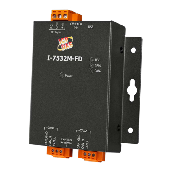
2. Technical data 2.1. Appearance Figure 2-1-1 Appearance of I-7532M-FD I-7532M-FD ( 2-port CAN/CAN FD Bridge ) User Manual (version 1.0.0) Page: 8 Copyright © 2020 ICP DAS Co., Ltd. All Rights Reserved. E-mail: service@icpdas.com... -
Page 9: Pin Assignment
2.2. Pin Assignment The pin assignments of CAN port and power connector of I-7532M-FD is shown in the following tables. Table 2-2-1 Pin Assignment Port Schematic diagram Description 1. CAN_GND CAN ground of CAN port 2. CAN_H CAN_High bus line of CAN port. -
Page 10: Led Indicator
2.3. LED Indicator There are 4 LEDs on the I-7532M-FD. One for power indication, one for usb indication and two for CAN bus indication. The LED assignment and description are shown as follows. Table 2-3-1 LED Description LED Name Status... -
Page 11: Terminal Resistor Setup
108Ω~132Ω). The bus topology and the positions of these terminal resistors are shown as following figure. Figure 2-4-1 CAN bus network topology Each I-7532M-FD includes two build-in 120Ω terminal resistor, users can decider to enabl it or not. The DIP switch for terminal resistor is on the upper of the CAN connector. - Page 12 Figure 2-4-4 Application 1 If your application is like the structure as follows, the terminal resistor is not needed. Figure 2-4-5 Application 2 I-7532M-FD ( 2-port CAN/CAN FD Bridge ) User Manual (version 1.0.0) Page: 12 Copyright © 2020 ICP DAS Co., Ltd. All Rights Reserved. E-mail: service@icpdas.com...
-
Page 13: Wire Connection
2.5. Wire Connection The wire connection of the I-7532M-FD is displayed below. Figure 2-5-1 Wire Connection for I-7532M-FD I-7532M-FD ( 2-port CAN/CAN FD Bridge ) User Manual (version 1.0.0) Page: 13 Copyright © 2020 ICP DAS Co., Ltd. All Rights Reserved. E-mail: service@icpdas.com... -
Page 14: Driving Capability
2.6. Driving Capability Before introducing the driving capability of the I-7532M-FD, some characteristics of copper cable must be assumed. The AC parameters are 120Ω impedance and 5ms/, line delay, and the DC parameter follows the table show below. Table 2-6-1 Recommended DC parameter for CAN Bus Line Wire Cross-Section [mm Resistance [Ω/km]... -
Page 15: Software Utility
3. Software Utility When users want to use user-defined CAN/CAN FD baud rate, CAN/CAN FD message filter and CAN mapping, merging, splitting rule function on the I-7532M-FD, the I-7532M-FD Utility tool may be needed. 3.1. Install the I-7532-FD Utility Step 1: Get the I-7532-FD Utility The software is located at: http://www.icpdas.com/en/download/show.php?num=3019&model=I-7532M-FD... - Page 16 2. Select the installation path of the I-7532-FD Utility and click the “Next” button. 3. Confirm the installation. Click the “Next” button to start the installation I-7532M-FD ( 2-port CAN/CAN FD Bridge ) User Manual (version 1.0.0) Page: 16 Copyright © 2020 ICP DAS Co., Ltd. All Rights Reserved. E-mail: service@icpdas.com...
- Page 17 4. Installation complete. Click the “Close” button to exit I-7532M-FD ( 2-port CAN/CAN FD Bridge ) User Manual (version 1.0.0) Page: 17 Copyright © 2020 ICP DAS Co., Ltd. All Rights Reserved. E-mail: service@icpdas.com...
-
Page 18: Setting Up The I-7532M-Fd
Utility and the I-7532M-FD. Here is the example for the I-7532M-FD configuration. Step 1: Connect the PC available USB port with the USB port of the I-7532M-FD. Users can find the communication cable (CA-USB10) in the product box. -
Page 19: Start To Use I-7532-Fd Utility Tool
3.3. Start to use I-7532-FD Utility tool Figure 3-3-1 Main frame of the I-7532M-FD Utility tool [Basic] This field is used to connect to the module and get device information, get device configuration, configure device, load device configuration from file and save device configuration to file. - Page 20 This field is used to check the CAN status of the device. This field is useful for user to check and analysis the device CAN network status (including no error, CAN bus off, error passive, error warning status and transmit/receive error counter information) . I-7532M-FD ( 2-port CAN/CAN FD Bridge ) User Manual (version 1.0.0) Page: 20...
-
Page 21: Get Device Configuration
3.3.1. Get Device Configuration Press the “Refresh” button to scan and list all the necessary I-7532M-FD modules on “Module Name” location. Then select the necessary I-7532M-FD module and press “Get Device Config.” button to start to connect and get device configuration. -
Page 22: Can Bus Configuration
CAN FD frame format as specified by the ISO11898-1. For “Non-ISO” specification setting, the module uses the CAN FD frame format as specified by Bosch CAN FD Specification V1.0. I-7532M-FD ( 2-port CAN/CAN FD Bridge ) User Manual (version 1.0.0) Page: 22... - Page 23 Can set “Rx CAN => CAN”, “Rx CAN FD => CAN”, “Rx CAN => CAN FD” and “Rx CAN FD => CAN FD”. When setting “Rx CAN => CAN” or “Rx CAN FD => CAN FD”, CAN or CAN FD I-7532M-FD ( 2-port CAN/CAN FD Bridge ) User Manual (version 1.0.0) Page: 23...
- Page 24 0 ~ 8) will be no changed and transform to CAN FD frame. Can set CAN FD frame with “BRS” (bit rate switch) or not. I-7532M-FD ( 2-port CAN/CAN FD Bridge ) User Manual (version 1.0.0) Page: 24...
-
Page 25: Forwarding Rule Examples
Frame on CAN network (port 2) port Driection CAN type Frame type Frame format Datalen Data 0x111 standard data 00-11-22-33-44-55-66-77 I-7532M-FD ( 2-port CAN/CAN FD Bridge ) User Manual (version 1.0.0) Page: 25 Copyright © 2020 ICP DAS Co., Ltd. All Rights Reserved. E-mail: service@icpdas.com... - Page 26 CAN type Frame type Frame format Datalen Data 00-11-22-33-44-55-66-77- CAN FD 0x111 standard Data+BRS 88-99-AA-BB-CC-DD-EE-FF I-7532M-FD ( 2-port CAN/CAN FD Bridge ) User Manual (version 1.0.0) Page: 26 Copyright © 2020 ICP DAS Co., Ltd. All Rights Reserved. E-mail: service@icpdas.com...
-
Page 27: Can Filter Configuration
[Reject Remote Frame] block: Click the “Reject Remote Standard/Extended Frame” item to select whether to reject remote standard/extended CAN frame or not I-7532M-FD ( 2-port CAN/CAN FD Bridge ) User Manual (version 1.0.0) Page: 27 Copyright © 2020 ICP DAS Co., Ltd. All Rights Reserved. E-mail: service@icpdas.com... - Page 28 [Standard ID/Extended ID] block: Press the “Add”, “Delete” button to add/delete a range of standard/extended CAN ID into filter frame. I-7532M-FD ( 2-port CAN/CAN FD Bridge ) User Manual (version 1.0.0) Page: 28 Copyright © 2020 ICP DAS Co., Ltd. All Rights Reserved. E-mail: service@icpdas.com...
-
Page 29: Can Mapping Rule Configuration
[F_Type] Standard or extended frame type 0: standard frame, 1: extended frame. *: no check. I-7532M-FD ( 2-port CAN/CAN FD Bridge ) User Manual (version 1.0.0) Page: 29 Copyright © 2020 ICP DAS Co., Ltd. All Rights Reserved. E-mail: service@icpdas.com... - Page 30 ID field of CAN/CAN FD frame *: no check. [Data(hex)] Data field of CAN/CAN FD frame *: no check. I-7532M-FD ( 2-port CAN/CAN FD Bridge ) User Manual (version 1.0.0) Page: 30 Copyright © 2020 ICP DAS Co., Ltd. All Rights Reserved. E-mail: service@icpdas.com...
- Page 31 In “Source ” field, checked items will be compared with the set value. In “Destination” field, checked items will be modified with the set value. I-7532M-FD ( 2-port CAN/CAN FD Bridge ) User Manual (version 1.0.0) Page: 31...
-
Page 32: Mapping Rule Examples
Frame on CAN network (port 2) port Driection CAN type Frame type Frame format Datalen Data 0x222 standard data 00-11-22-33-44-55-66-77 I-7532M-FD ( 2-port CAN/CAN FD Bridge ) User Manual (version 1.0.0) Page: 32 Copyright © 2020 ICP DAS Co., Ltd. All Rights Reserved. E-mail: service@icpdas.com... - Page 33 Driection Frame type Datalen Data type format CAN FD 0x00000002 extended data + BRS 00-11-22-33-44-55-66-77 I-7532M-FD ( 2-port CAN/CAN FD Bridge ) User Manual (version 1.0.0) Page: 33 Copyright © 2020 ICP DAS Co., Ltd. All Rights Reserved. E-mail: service@icpdas.com...
-
Page 34: Can Merging Rule Configuration
“Add” button to add a new rule or press the “Modify” button to modify the selected rule. I-7532M-FD ( 2-port CAN/CAN FD Bridge ) User Manual (version 1.0.0) Page: 34... - Page 35 The “Stuff Byte” value will be stuffed into CAN FD frame data field when the sum of all CAN frames data length is less than the CAN FD frame “DL” value. I-7532M-FD ( 2-port CAN/CAN FD Bridge ) User Manual (version 1.0.0) Page: 35 Copyright ©...
-
Page 36: Merging Rule Examples
Frame type Frame format Datalen Data 00-01-02-03-04-05-06-07- CAN FD 0x111 standard Data + BRS 08-09-0A-0B-0C-0D-0E-0F- 10-11-12-13-14-15-16-17 I-7532M-FD ( 2-port CAN/CAN FD Bridge ) User Manual (version 1.0.0) Page: 36 Copyright © 2020 ICP DAS Co., Ltd. All Rights Reserved. E-mail: service@icpdas.com... - Page 37 Frame format Datalen Data 00-01-02-03-04-05-06-07- 08-09-0A-0B-0C-0D-0E-0F- CAN FD 0x111 standard Data + BRS 10-11-12-13-14-15-16-17- FF-FF-FF-FF-FF-FF-FF-FF I-7532M-FD ( 2-port CAN/CAN FD Bridge ) User Manual (version 1.0.0) Page: 37 Copyright © 2020 ICP DAS Co., Ltd. All Rights Reserved. E-mail: service@icpdas.com...
-
Page 38: Can Splitting Rule Configuration
User can press the “Add” button to add a new rule or press the “Modify” button to modify the selected rule. I-7532M-FD ( 2-port CAN/CAN FD Bridge ) User Manual (version 1.0.0) Page: 38... - Page 39 CAN frames can not large than the CAN FD frame “DL” value. In the same splitting rule, each CAN frames IDs are different to each other. I-7532M-FD ( 2-port CAN/CAN FD Bridge ) User Manual (version 1.0.0) Page: 39...
-
Page 40: Splitting Rule Examples
00-01-02-03-04-05-06-07 0x002 standard data 08-09-0A-0B-0C-0D-0E-0F 0x003 standard data 10-11-12-13-14-15-16-17 0x004 standard data 18-19-1A-1B-1C-1D-1E-1F I-7532M-FD ( 2-port CAN/CAN FD Bridge ) User Manual (version 1.0.0) Page: 40 Copyright © 2020 ICP DAS Co., Ltd. All Rights Reserved. E-mail: service@icpdas.com... - Page 41 Frame format Datalen Data 0x001 standard data 00-01-02-03-04-05 0x002 standard data 06-07-08-09-0A-0B 0x003 standard data 0C-0D-0E-0F I-7532M-FD ( 2-port CAN/CAN FD Bridge ) User Manual (version 1.0.0) Page: 41 Copyright © 2020 ICP DAS Co., Ltd. All Rights Reserved. E-mail: service@icpdas.com...
-
Page 42: Can Status Information
[RxEC] Receive error counter of the device CAN port. Current value of the receive error counter. I-7532M-FD ( 2-port CAN/CAN FD Bridge ) User Manual (version 1.0.0) Page: 42 Copyright © 2020 ICP DAS Co., Ltd. All Rights Reserved. E-mail: service@icpdas.com... -
Page 43: Firmware Upgrade
Step 1: Power off the I-7532M-FD. Step 2: Set the Init. dip switch to ‘ON’ position. Step 3: Power on the I-7532M-FD, the red and green leds of USB, CAN1 and CAN2 will polling to flash per 200 milliseconds. Step 4: Connect the PC available USB port with the USB port of the I-7532M-FD. Users can find the communication cable (CA-USB10) in the product box. - Page 44 Step 7: Execute the “Firmware Update Tool”. Step 8: Select USB port and the necessary USB Disk of PC I-7532M-FD ( 2-port CAN/CAN FD Bridge ) User Manual (version 1.0.0) Page: 44 Copyright © 2020 ICP DAS Co., Ltd. All Rights Reserved. E-mail: service@icpdas.com...
- Page 45 Step 10: Press the “Firmware Update” button to update the firmware. After successfully to update the firmware, the “Firmware Update Success! Please Reboot Module!” information will be display on the “3. Firmware Update” frame. I-7532M-FD ( 2-port CAN/CAN FD Bridge ) User Manual (version 1.0.0) Page: 45...
- Page 46 Step 11: Set the Init. dip switch to the “Off” position and reboot the module.Then press the “Exit” button to exit. I-7532M-FD ( 2-port CAN/CAN FD Bridge ) User Manual (version 1.0.0) Page: 46 Copyright © 2020 ICP DAS Co., Ltd. All Rights Reserved. E-mail: service@icpdas.com...
-
Page 47: Appendix
This chapter provides revision history information to this document. The table below shows the revision history. Revision Date Description 1.0.0 2020/10/05 Initial issue I-7532M-FD ( 2-port CAN/CAN FD Bridge ) User Manual (version 1.0.0) Page: 47 Copyright © 2020 ICP DAS Co., Ltd. All Rights Reserved. E-mail: service@icpdas.com... -
Page 48: Dimension
5.2. Dimension I-7532M-FD ( 2-port CAN/CAN FD Bridge ) User Manual (version 1.0.0) Page: 48 Copyright © 2020 ICP DAS Co., Ltd. All Rights Reserved. E-mail: service@icpdas.com...
Need help?
Do you have a question about the I-7532M-FD and is the answer not in the manual?
Questions and answers