Table of Contents
Advertisement
Quick Links
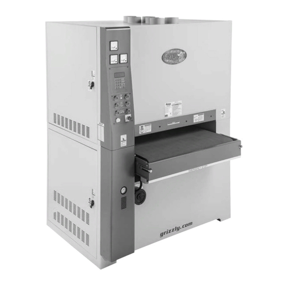
MODEL G0866
37" WIDE BELT SANDER
w/INDUSTRIAL ROLLER
OWNER'S MANUAL
(For models manufactured since 11/18)
COPYRIGHT © MARCH, 2021 BY GRIZZLY INDUSTRIAL, INC.
WARNING: NO PORTION OF THIS MANUAL MAY BE REPRODUCED IN ANY SHAPE
OR FORM WITHOUT THE WRITTEN APPROVAL OF GRIZZLY INDUSTRIAL, INC.
#CS20266 PRINTED IN TAIWAN
V1.03.21
Advertisement
Table of Contents

Related Manuals for Grizzly G0866


Summary of Contents for Grizzly G0866
- Page 1 (For models manufactured since 11/18) COPYRIGHT © MARCH, 2021 BY GRIZZLY INDUSTRIAL, INC. WARNING: NO PORTION OF THIS MANUAL MAY BE REPRODUCED IN ANY SHAPE OR FORM WITHOUT THE WRITTEN APPROVAL OF GRIZZLY INDUSTRIAL, INC. #CS20266 PRINTED IN TAIWAN V1.03.21...
- Page 2 This manual provides critical safety instructions on the proper setup, operation, maintenance, and service of this machine/tool. Save this document, refer to it often, and use it to instruct other operators. Failure to read, understand and follow the instructions in this manual may result in fire or serious personal injury—including amputation, electrocution, or death.
-
Page 3: Table Of Contents
Table of Contents INTRODUCTION ..........2 SECTION 7: SERVICE ........45 Contact Info............ 2 Troubleshooting ........... 45 Manual Accuracy ........... 2 Calibrating Digital Display ......48 Identification ........... 3 Adjusting Belt Tracking Limit Switches ..48 Controls & Components ......... 4 Adjusting Oscillation Timing &... -
Page 4: Introduction
ID label (see below). This information is required for us to provide proper tech support, and it helps us determine if updated documenta- tion is available for your machine. Manufacture Date Serial Number Model G0866 (Mfd. Since 11/18) -
Page 5: Identification
Gauge & Air Jet Belt Belt Tension Tension Limit Switch Platen Knob Height Dial Belt Tracking Drum Height Limit Switch Adjustment Oscillation Bolt Lock Post Airflow & Speed Release Controls Drum Height Lever Locking Bolt Model G0866 (Mfd. Since 11/18) -
Page 6: Controls & Components
K. Conveyor Belt Stop Button: Turns feed motor OFF when pressed. Emergency Stop Button: Turns all machine functions OFF when pressed; engages emer- gency brake to stop rotation of sanding drums. Twist clockwise to reset in order to start sander again. Model G0866 (Mfd. Since 11/18) - Page 7 Rotate clock- wise to lower table; rotate counterclockwise to raise table. One full rotation moves the table approximately 0.20". Q. Conveyor Table: Supports workpiece dur- ing operations; can be raised and lowered according to workpiece thickness. Model G0866 (Mfd. Since 11/18)
- Page 8 AD. Belt Limit Switches: Stop sanding drum ply of 75 PSI with a " air hose. Regulates motor if sanding belt tension or tracking is incoming air pressure for sanding belt oscilla- incorrect. tion when handle is in open position. Model G0866 (Mfd. Since 11/18)
-
Page 9: Machine Data Sheet
MACHINE DATA SHEET Customer Service #: (570) 546-9663 · To Order Call: (800) 523-4777 · Fax #: (800) 438-5901 MODEL G0866 37" 15 HP WIDE‐BELT SANDER WITH INDUSTRIAL ROLLER Product Dimensions: Weight................................3417 lbs. Width (side-to-side) x Depth (front-to-back) x Height................59 x 65 x 75 in. - Page 10 The information contained herein is deemed accurate as of 3/29/2021 and represents our most recent product specifications. Model G0866 PAGE 2 OF 3 Due to our ongoing improvement efforts, this information may not accurately describe items previously purchased. Model G0866 (Mfd. Since 11/18)
- Page 11 The information contained herein is deemed accurate as of 3/29/2021 and represents our most recent product specifications. Model G0866 PAGE 3 OF 3 Due to our ongoing improvement efforts, this information may not accurately describe items previously purchased. Model G0866 (Mfd. Since 11/18)
-
Page 12: Section 1: Safety
Never operate under the influence of drugs or injury or blindness from flying particles. Everyday alcohol, when tired, or when distracted. eyeglasses are NOT approved safety glasses. -10- Model G0866 (Mfd. Since 11/18) - Page 13 Make sure they are properly installed, you experience difficulties performing the intend- undamaged, and working correctly BEFORE ed operation, stop using the machine! Contact our operating machine. Technical Support at (570) 546-9663. -11- Model G0866 (Mfd. Since 11/18)
-
Page 14: Additional Safety For Wide Belt Sanders
If normal safety pre- respect. Failure to do so could result in cautions are overlooked or ignored, seri- serious personal injury, damage to equip- ous personal injury may occur. ment, or poor work results. -12- Model G0866 (Mfd. Since 11/18) -
Page 15: Section 2: Power Supply
Nominal Voltage ......440V, 480V sure it is connected to a power supply circuit that Cycle ............60 Hz meets the specified circuit requirements. Phase ............ 3-Phase Power Supply Circuit ......50 Amps -13- Model G0866 (Mfd. Since 11/18) - Page 16 Locking Disconnect Switch Power Source Machine Conduit Conduit Ground Ground Figure 11. Model G7978 15 HP Rotary Phase Converter. Figure 10. Typical setup of a permanently connected machine. -14- Model G0866 (Mfd. Since 11/18)
-
Page 17: Converting Voltage To 440V
(see Figure 13) and connect it to to 440V 440V terminal. 220V Terminal 440V Terminal The Model G0866 is prewired to operate on 220V power, but it can be converted for 440V operation using the optional conversion kit (Model G440VG0866), which contains two replacement "1" Wire overload relays. - Page 18 REAR MAIN MOTOR (440V) MOTOR (220V) Figure 16. Main motors wired for 220V. Figure 18. Table elevation motor junction box. (Motor Rewired for 440V) To Electrical Box -16- Model G0866 (Mfd. Since 11/18) (Motor Rewired for 440V) To Electrical Box...
- Page 19 16. Close table elevation motor junction box. FEED MOTOR (440V) FEED MOTOR (220V) Figure 23. Feed motor wired for 440V. 20. Close feed motor junction box. 21. Close electrical box and lower left access door. -17- Model G0866 (Mfd. Since 11/18)
-
Page 20: Section 3: Setup
IMPORTANT: Save all packaging materials until you are completely satisfied with the machine and have resolved any issues between Grizzly or the shipping agent. You MUST have the original pack- aging to file a freight claim. It is also extremely helpful if you need to return your machine later. -
Page 21: Inventory
O. Hex Wrench Set (1.5–10mm) ..... 1 ing or they are pre-installed at the factory. Flexible Grease Gun Extension ....1 Q. Door Keys ........... 2 R. Tool Box (Not Pictured) ......1 Figure 24. Loose item inventory. -19- Model G0866 (Mfd. Since 11/18) -
Page 22: Cleanup
Figure 25. T23692 Orange Power Degreaser. Repeat Steps 2–3 as necessary until clean, then coat all unpainted surfaces with a quality metal protectant to prevent rust. -20- Model G0866 (Mfd. Since 11/18) -
Page 23: Site Considerations
Wall = Electrical Connection = Min. 30" for Maintenance Keep Outfeed Area Unobstructed 65" 121" Keep Loading Area Unobstructed Figure 26. Minimum working clearances. -21- Model G0866 (Mfd. Since 11/18) -
Page 24: Lifting & Placing
Move machine to its prepared location while it is still attached to shipping pallet. Forklift Fork Figure 28. Example of lifting machine with forklift example. Lift sander off pallet, remove pallet, then slowly lower sander into position. -22- Model G0866 (Mfd. Since 11/18) -
Page 25: Leveling
(see Figure 29). Flat Washer Machine Base Leveling Bolts Lag Shield Anchor Concrete Drilled Hole Figure 30. Popular method for anchoring machinery to a concrete floor. Figure 29. Leveling bolt locations. Close access panels. -23- Model G0866 (Mfd. Since 11/18) -
Page 26: Assembly
(if applicable). Increase Assembly of the Model G0866 consists of install- Lock Unlock ing the air line and the sanding belt, and verifying the factory-set pressure roller settings. - Page 27 Fork side against table saw fence to cut opposite side of workpiece parallel. IMPORTANT: 2x4 MUST have uniform thick- ness for following steps to be completed Figure 34. Sanding belt placement components. correctly. -25- Model G0866 (Mfd. Since 11/18)
-
Page 28: Dust Collection
Reduce your risk by wearing a respirator and capturing the dust with a dust-collection system. Minimum CFM for Model G0866: 3600 CFM Figure 36. 2x4 positioned to check pressure Do not confuse this CFM recommendation with roller height. -
Page 29: Power Connection
3-Phase power as it could damage or decrease the life of sensitive electrical components. NOTICE The Model G0866 is prewired for 220V. If Incoming Power you plan to operate machine at 440V, you Strain Relief must refer to instructions on Page 15. - Page 30 "R" and connected to the power source. "S" terminals (see Figure 43). R and S Terminals Figure 41. Connecting power to machine. Figure 43. Location of "R" and "S" terminals. -28- Model G0866 (Mfd. Since 11/18)
-
Page 31: Test Run
Operating an improperly set up machine may result in malfunction or unexpect- ed results that can lead to serious injury, Table Down death, or machine/property damage. Figure 45. Table controls. -29- Model G0866 (Mfd. Since 11/18) - Page 32 Congratulations! The Test Run ing belt start button. The machine should not is complete. start. — If the machine does not start, the safety feature of the Emergency Stop button is working correctly. Proceed to next step. -30- Model G0866 (Mfd. Since 11/18)
-
Page 33: Section 4: Operations
13. Repeats Steps 9–12 as needed, turns all ects. Regardless of the content in this sec- motors OFF, disconnects machine from tion, Grizzly Industrial will not be held liable power, then turns OFF air compressor once for accidents caused by lack of training. -
Page 34: Sanding Workpieces
Platen on Page 36 for more information about is facing table. On the contrary, a workpiece platen positions. supported on bowed side will rock during sanding, and could cause kickback or severe injury. -32- Model G0866 (Mfd. Since 11/18) - Page 35 DOC for the *0.003" *0.005" 0.002" Down 0.5mm platen setting (up, even, or down). 0.001" *0.003" 0.001" Down 1mm *These numbers assume the platen is raised up during the sanding pass. -33- Model G0866 (Mfd. Since 11/18)
-
Page 36: Sanding Tips
(aka "Butt Feeding"). • Feed boards into the machine at different points on the conveyor to maximize sandpa- per life and prevent uneven belt wear. -34- Model G0866 (Mfd. Since 11/18) -
Page 37: Installing/Changing Sanding Belts
180-Grit ............. 1 Detensioned Tension Position Position The Model G0866 only accepts 37" wide by 75" long sanding belts. For additional sanding Figure 51. Sanding belt tension knob positions. belt selections beyond those included with the machine, refer to Accessories on Page 39. -
Page 38: Adjusting Platen
Due to the cushioned- 11. Close upper left access door. construction, the platen is less likely to leave belt- splice or chatter marks. -36- Model G0866 (Mfd. Since 11/18) -
Page 39: Changing Feed Rate
Turn knob clockwise to increase feed rate. Turn knob counterclockwise to decrease feed rate. If workpiece has straight notches across it, graphite cloth and felt have worn out and Note: Turn knob in ⁄ " increments. need to be replaced. -37- Model G0866 (Mfd. Since 11/18) -
Page 40: Reading Amp Load Meters
Keep amp draw within GREEN load range shown on the AMP LOAD CHART. If you operate machine in RED load range, motor damage may occur and will not be covered under warranty. -38- Model G0866 (Mfd. Since 11/18) -
Page 41: Section 5: Accessories
H8846—60-Grit cause machine to malfunction, resulting in H8847—80-Grit serious personal injury or machine damage. H8848—100-Grit To reduce this risk, only install accessories H8849—120-Grit recommended for this machine by Grizzly. H8850—150-Grit H8835—60-Grit (3-Pk.) H8836—80-Grit (3-Pk.) NOTICE H8837—100-Grit (3-Pk.) H8838—120-Grit (3-Pk.) Refer to our website or latest catalog for H8839—150-Grit (3-Pk.) - Page 42 Figure 64. Model T26419 Syn-O-Gen Synthetic Grease. Figure 62. Model H4228 Anti-Fatigue Mat. www.grizzly.com 1-800-523-4777 order online at or call -40- Model G0866 (Mfd. Since 11/18)
-
Page 43: Section 6: Maintenance
To reduce risk of shock or accidental startup, always disconnect machine from power before adjustments, Cleaning the Model G0866 is relatively easy. maintenance, or service. Vacuum excess wood chips and sawdust, and wipe off the remaining dust with a dry cloth. If any... - Page 44 Figure 65. Location of conveyor belt roller axle grease fitting. Leadscrew (1 of 4) Motor Belt (1 of 2) Figure 67. Location of table elevation leadscrews, chain, and sprockets. Figure 66. Locations of upper left/right sanding belt roller axle grease fittings. -42- Model G0866 (Mfd. Since 11/18)
-
Page 45: Emptying Dust And Water Traps
(see Figure 70). To empty these, turn air pressure OFF, allow pressure to bleed out, then unscrew and empty bowls. Dust Trap Bowl (1 of 2) Figure 70. Location of dust cups. -43- Model G0866 (Mfd. Since 11/18) -
Page 46: Cleaning Sanding Belt
Figure 71. PRO-STIK cleaning pad in use. To clean sanding belt: Set table to thickness of cleaning pad. Run pad through sander two or three times. DO NOT take too deep of a cut—belt should barely touch cleaning pad. -44- Model G0866 (Mfd. Since 11/18) -
Page 47: Section 7: Service
9. Motor or motor bearings at fault. 9. Replace motor. Table moves up 1. Power connections wired out of phase. 1. Correct phase polarity (Page 28). when it should move down and down when it should move -45- Model G0866 (Mfd. Since 11/18) - Page 48 5. Replace graphite or felt pad (Page 51). 5. Graphite or felt pad worn/damaged. 6. Using amp load meter to establish material 6. Use alternate methods to establish material removal amount (Page 34). removal amount. -46- Model G0866 (Mfd. Since 11/18)
- Page 49 2. Water filter/trap drain cock left open. 2. Ensure water filter/trap drain cock is tight. 3. Air line ruptured or air leaking at a connection 3. Locate source of sound and determine likely cause point. based on visual evidence. -47- Model G0866 (Mfd. Since 11/18)
-
Page 50: Calibrating Digital Display
Figure 72. Digital display calibration keys. approximately ⁄ " apart. Tighten bolt and repeat adjustment with other side and other sanding belt if necessary. Start machine and make sure it is working properly. -48- Model G0866 (Mfd. Since 11/18) -
Page 51: Adjusting Oscillation Timing & Speed
Remove sanding belt and turn belt tension knob to tensioned position. These adjustments should be made with care, as current sanding belt oscillation and timing settings can only be observed when doors are open and sanding belts are moving. -49- Model G0866 (Mfd. Since 11/18) - Page 52 Tighten down knob when satisfied. Figure 78. Speed adjustment components. Turn speed adjustment knob clockwise to decrease oscillation speed and counterclock- wise to increase. Tighten lock nut to secure speed adjustment. -50- Model G0866 (Mfd. Since 11/18)
-
Page 53: Servicing Platen
Install sanding belt, stop block, and lock post release lever, then close left access door. Stop Block Figure 79. Lock post release lever and stop block locations. -51- Model G0866 (Mfd. Since 11/18) -
Page 54: Checking/Replacing Brake Pads
Air Valve Open (in Down Position) Figure 82. Location of disc brake assembly and rotor. Air Supply Disconnected Figure 84. Air supply disconnected, and air valve opened for brake service. Open lower right access panel. -52- Model G0866 (Mfd. Since 11/18) - Page 55 Air Line Lock Nut Front Figure 86. Brake pad measurement. Brake Guard Note: Rear motor brake assembly has two air Figure 90. Location of front brake guard, cap connections to disconnect. screws, and gasket. -53- Model G0866 (Mfd. Since 11/18)
- Page 56 12. Install new outer brake pad then secure with bushing, spring, mounting plate, and flat head screw. Make sure to re-install compo- nents in same order and orientation as they were removed (see Figure 93). -54- Model G0866 (Mfd. Since 11/18)
-
Page 57: Checking/Adjusting Table Parallelism
Adjust table elevation until it is approximately 6" below sanding belt. Figure 94. Table elevation leadscrew flanges Take precise measurement of wood block located on underside of table. (approx. 4" long) and record measurement. -55- Model G0866 (Mfd. Since 11/18) - Page 58 0.015" between the right and left sides. Rotating left will lower table and rotating right with raise table. Tip: It may help to rotate elevation leadscrew flange with a vise grip if it is difficult to move. -56- Model G0866 (Mfd. Since 11/18)
- Page 59 13. Check table parallelism (refer to Checking Table Parallelism on Page 55) and, if nec- essary, repeat Steps 2–12 until all corners of table are the same distance from upper frame. 14. Remove wood block and close lower access panels. -57- Model G0866 (Mfd. Since 11/18)
-
Page 60: Checking/Adjusting Pressure Rollers
Open upper right access door and remove V-belts from main motors and sanding drums (refer to Changing V-Belts on Page 60 for more information). Right Side Infeed Outfeed Figure 102. Locations of pressure roller adjust- ment components. -58- Model G0866 (Mfd. Since 11/18) -
Page 61: Checking/Adjusting V-Belt Tension
Open-End Wrench 12mm ........1 Figure 104). To check/adjust V-belt tension: V-Belt Jam Nut DISCONNECT MACHINE FROM POWER! Jam Nut Open lower left and right access panels. V-Belt Adjustment Adjustment Figure 104. V-belt tension adjustment components. -59- Model G0866 (Mfd. Since 11/18) -
Page 62: Changing V-Belts
Changing Table Elevation V-Belt Tools Needed Open-End Wrench 12mm ........1 To change table elevation V-belt: DISCONNECT MACHINE FROM POWER! Table Pulley Open lower left access panel. Motor Pulley Figure 106. Location of table and motor pulleys. -60- Model G0866 (Mfd. Since 11/18) - Page 63 Prepare two 12" long wood blocks of equal Roller Centering thickness and place them under rubber roll- Washer ers for support. Figure 109. Location of centering washer cap screws and square frame end Phillips head screws. -61- Model G0866 (Mfd. Since 11/18)
-
Page 64: Adjusting Conveyor Belt Tension
Pulleys (1 of 2 Shown) Figure 113. Location of conveyor belt adjust- ment bolts (1 of 2 shown). Tool Needed: Open-End Wrench 19mm ........1 Motor Pulleys Figure 112. Location of drum and motor pulleys. -62- Model G0866 (Mfd. Since 11/18) -
Page 65: Adjusting Conveyor Belt Tracking
(1 of 2 shown). Repeat Steps 1–2, as necessary, until con- veyor belt is properly tracking. Note: The edge of the conveyor belt should just touch the guide wheels as shown in Figure 115. -63- Model G0866 (Mfd. Since 11/18) -
Page 66: Replacing Conveyor Belt
17. With assistant, install gearbox and mounting bracket. 18. Install EMERGENCY STOP! panel assembly and limit switch. 19. Refer to Adjusting Conveyor Belt Tracking on Page 63 to adjust belt tracking. Figure 116. Example of marking leadscrew for re-assembly. -64- Model G0866 (Mfd. Since 11/18) -
Page 67: Conveyor Belt Removal Sequence
Conveyor Belt Removal Sequence WARNING DISCONNECT POWER! Table Guide Tracking Adjustment Bolts Figure 117. Conveyor belt removal sequence. -65- Model G0866 (Mfd. Since 11/18) -
Page 68: Pneumatic System Diagram
Pneumatic System Diagram Cylinder Switch Piston Cylinder Diaphragm Manifold Fork Regulator Manifold Solenoid Brake -66- Model G0866 (Mfd. Since 11/18) -
Page 69: Pneumatic System Component Photos
Figure 121. Regulator. Brakes. From Cylinder Switch To Diaphragm From Manifold #1 From Manifold #1 Figure 119. Fork. Figure 122. Piston and cylinder. To Manifold #1 From Manifold #1 From Fork Figure 120. Diaphragm. -67- Model G0866 (Mfd. Since 11/18) -
Page 70: Section 8: Wiring
Technical Support at (570) 546-9663. The photos and diagrams included in this section are best viewed in color. You can view these pages in color at www.grizzly.com. -68- Model G0866 (Mfd. Since 11/18) -
Page 71: Component Locations
Air Pressure Limit Switch (Page 79) Table Elevation Sensors (Page 78) Sanding Belt Tracking Limit Switches Sanding Belt Tension Limit Switches (Page 78) (Page 78) Conveyor Feed Motor (Page 76) READ ELECTRICAL SAFETY -69- Model G0866 (Mfd. Since 11/18) ON PAGE 68! -
Page 72: Electrical Overview
Feed Motor Sanding Drum Motor DISCONNECT SWITCH (as recommended ) Ground EMERGENCY 3-PHASE STOP! Plate 220 VAC Limit Switch Table Elevation Limit Switches Sanding Belt Tracking/ Tension Limit Switches READ ELECTRICAL SAFETY -70- Model G0866 (Mfd. Since 11/18) ON PAGE 68! -
Page 73: Electrical System Wiring Schematic
Electrical System Wiring Schematic READ ELECTRICAL SAFETY -71- Model G0866 (Mfd. Since 11/18) ON PAGE 68! -
Page 74: Electrical Box
Electrical Box Amperage Gauges Transformer Fuses Contactors Contactors Relay Power Supply Terminals Relays Terminal Bars Figure 123. Inside electrical box. READ ELECTRICAL SAFETY -72- Model G0866 (Mfd. Since 11/18) ON PAGE 68! -
Page 75: Electrical Box Wiring Schematic (220V)
Electrical Box Wiring Schematic (220V) 220V Terminal Figure 124. Location of 220V power supply terminal on transformer. READ ELECTRICAL SAFETY -73- Model G0866 (Mfd. Since 11/18) ON PAGE 68! -
Page 76: Electrical Box Wiring Schematic (440V)
Electrical Box Wiring Schematic (440V) 440V Terminal Figure 125. Location of 440V voltage conversion terminal on transformer. READ ELECTRICAL SAFETY -74- Model G0866 (Mfd. Since 11/18) ON PAGE 68! -
Page 77: Main Motor Wiring
(Motor Rewired for 440V) To Electrical Box Motor Junction Box 2 Access Panel Motor Junction Box 1 Figure 127. Main motor junction box. Figure 126. Motor junction box locations. READ ELECTRICAL SAFETY -75- Model G0866 (Mfd. Since 11/18) ON PAGE 68! - Page 78 To Electrical Box Figure 128. Table elevation motor junction box. Figure 129. Feed motor junction box. To Electrical Box (Motor Rewired for 440V) FEED MOTOR (440V) FEED MOTOR (220V) READ ELECTRICAL SAFETY -76- Model G0866 (Mfd. Since 11/18) ON PAGE 68!
-
Page 79: Control Panel & Meters Wiring
Control Panel & Meters Wiring Figure 130. Back of 1st amp meter. Figure 131. Back of control panel. READ ELECTRICAL SAFETY -77- Model G0866 (Mfd. Since 11/18) ON PAGE 68! -
Page 80: Limit Switches & Sensors Wiring
Limit Switches Conveyer Feed Speed Belt Tracking Sensor Limit Switch Figure 132. Belt tension and tracking limit Figure 133. Table elevation limit switches and switches. conveyer feed speed sensor. READ ELECTRICAL SAFETY -78- Model G0866 (Mfd. Since 11/18) ON PAGE 68! -
Page 81: Air Pressure Limit Switch Wiring
Figure 134. EMERGENCY STOP! plate limit Figure 135. Table elevation proximity switch. switch. Air Pressure Limit Switch Wiring To Electrical Box Air Pressure Limit Switch Figure 136. Air pressure limit switch wiring. READ ELECTRICAL SAFETY -79- Model G0866 (Mfd. Since 11/18) ON PAGE 68! -
Page 82: Section 9: Parts
SECTION 9: PARTS We do our best to stock replacement parts when possible, but we cannot guarantee that all parts shown are available for purchase. Call (800) 523-4777 or visit www.grizzly.com/parts to check for availability. Tool Box & Accessories REF PART #... -
Page 83: Sanding Motor System
1312 1112 1111 1302-2 1302 1117 1303 1304 1313 1305 1301 1301-1 1310 1311 1306 1123 1310 1307 1122 1308 1121 BUY PARTS ONLINE AT GRIZZLY.COM! -81- Model G0866 (Mfd. Since 11/18) Scan QR code to visit our Parts Store. - Page 84 CAP SCREW 1/4-20 X 1/2 1126 P08661126 LIMIT SWITCH MOUJEN ME-8111 1313 P08661313 BRAKE GASKET 1 X 110 100 1127 P08661127 LIMIT SWITCH PLATE BUY PARTS ONLINE AT GRIZZLY.COM! -82- Model G0866 (Mfd. Since 11/18) Scan QR code to visit our Parts Store.
- Page 85 2339 2301 2317 2302 2303 2322 2303 2327 2304 2332 2326 2341 2324 2327 2323 2333 2305 2316 2325 2328 2327 BUY PARTS ONLINE AT GRIZZLY.COM! -83- Model G0866 (Mfd. Since 11/18) Scan QR code to visit our Parts Store.
- Page 86 LOCK WASHER 5/16 2318 P08662318 LOCK WASHER 5/16 2410 P08662410 HEX BOLT 5/16-18 X 3/4 2319 P08662319 HEX BOLT 5/16-18 X 3/4 BUY PARTS ONLINE AT GRIZZLY.COM! -84- Model G0866 (Mfd. Since 11/18) Scan QR code to visit our Parts Store.
-
Page 87: Conveyor System
ELEVATION LIMIT BLOCK 3132 P08663132 CAP SCREW 3/8-16 X 3/4 3206 P08663206 CAP SCREW 1/4-20 X 1-1/2 3133 P08663133 INFEED ROLLER BRACKET (LEFT) BUY PARTS ONLINE AT GRIZZLY.COM! -85- Model G0866 (Mfd. Since 11/18) Scan QR code to visit our Parts Store. -
Page 88: Feed Roller
P08664313 PISTON BRACKET (MIDDLE) 4205 P08664205 SET SCREW 1/4-20 X 1/2 4314 P08664314 FIXED BRACKET (LEFT) 4206 P08664206 HEX NUT 1/4-20 BUY PARTS ONLINE AT GRIZZLY.COM! -86- Model G0866 (Mfd. Since 11/18) Scan QR code to visit our Parts Store. -
Page 89: Sanding Drum
5119 5120 5106 5207 5113 5110 5111 5104 5116 5208 5103 5102 5104 5105 5106 5109 5107 5101 5108 5110 5111 BUY PARTS ONLINE AT GRIZZLY.COM! -87- Model G0866 (Mfd. Since 11/18) Scan QR code to visit our Parts Store. - Page 90 HEX BOLT 1/2-12 X 1 5204 P08665204 BALL BEARING 6206-2RS 5322 P08665322 LOCK WASHER 3/8 5205 P08665205 MIDDLE SANDING DRUM PULLEY BUY PARTS ONLINE AT GRIZZLY.COM! -88- Model G0866 (Mfd. Since 11/18) Scan QR code to visit our Parts Store.
-
Page 91: Upper Roller System
6131 6132 6130 6121 6131 6127 6122 6130 6133 6324 6140 6126 6124 6123 6124 6322 6134 6135 6136 6125-1 6125 BUY PARTS ONLINE AT GRIZZLY.COM! -89- Model G0866 (Mfd. Since 11/18) Scan QR code to visit our Parts Store. - Page 92 P08666133 CAP SCREW 10-24 X 3/4 6335 P08666335 PLATEN PRESSURE INDICATOR 6134 P08666134 HEX NUT 10-24 6336 P08666336 HEX NUT 1/4-20 BUY PARTS ONLINE AT GRIZZLY.COM! -90- Model G0866 (Mfd. Since 11/18) Scan QR code to visit our Parts Store.
-
Page 93: Cabinet Assembly
HEX BOLT M6-1 X 16 7107 P08667107 CAP SCREW 5/16-18 X 3/4 7116 P08667116 DOOR (LEFT) LOWER FRAME 7108 P08667108 FLAT WASHER 5/16 BUY PARTS ONLINE AT GRIZZLY.COM! -91- Model G0866 (Mfd. Since 11/18) Scan QR code to visit our Parts Store. -
Page 94: Main Wiring Panel & Controls
LR3D-325 LR3D-08 8133 8128 Relay Relay 8105 RESET RESET 8137 STOP STOP 8132 8129 8138 8139 8130 8107A 8140 8108 8131 BUY PARTS ONLINE AT GRIZZLY.COM! -92- Model G0866 (Mfd. Since 11/18) Scan QR code to visit our Parts Store. - Page 95 8143-1 P08668143-1 OL RELAY SCHN 440V 18.4A LR3D-325 8120 P08668120 LOCK WASHER 1/4 8143-2 P08668143-2 OL RELAY SCHN 3.7A LR3D-08 8121 P08668121 HEX BOLT 1/4-20 X 1/2 BUY PARTS ONLINE AT GRIZZLY.COM! -93- Model G0866 (Mfd. Since 11/18) Scan QR code to visit our Parts Store.
-
Page 96: Belt Oscillation System
9117 9129 9111 9107 9103 9125 9102 9106 9111 9113 9114 9105 9110 9101 9112 9109 9108 9128 9139 9127 9140 BUY PARTS ONLINE AT GRIZZLY.COM! -94- Model G0866 (Mfd. Since 11/18) Scan QR code to visit our Parts Store. - Page 97 CONNECTOR 1/4N X 3/8T 9142 P08669142 AIR MANIFOLD 4-PORT 9121 P08669121 CONNECTOR 1/4N X 1/8T 90° 9143 P08669143 AIR SWITCH 1/8 BUY PARTS ONLINE AT GRIZZLY.COM! -95- Model G0866 (Mfd. Since 11/18) Scan QR code to visit our Parts Store.
-
Page 98: Labels & Cosmetics
PREWIRED 220V LABEL 9217 P08669217 SWITCH DISPLAY NOTICE LABEL FOR GRIZZLY MACHINES ONLY! DO NOT REPRODUCE OR CHANGE THIS ARTWORK WITHOUT WRITTEN APPROVAL! Grizzly will not accept labels changed without approval. 9208 P08669208 RESPIRATOR/GLASSES LABEL 9218 P08669218 TOUCH-UP PAINT, GRIZZLY PUTTY artwork changes are required, contact us immediately at manuals@grizzly.com. -
Page 99: Warranty & Returns
WARRANTY & RETURNS Grizzly Industrial, Inc. warrants every product it sells for a period of 1 year to the original purchaser from the date of purchase. This warranty does not apply to defects due directly or indirectly to misuse, abuse, negligence, accidents, repairs or alterations or lack of maintenance.
Need help?
Do you have a question about the G0866 and is the answer not in the manual?
Questions and answers