Table of Contents
Advertisement
Quick Links
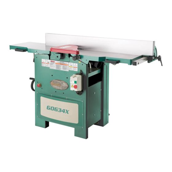
MODEL G0634X
12" JOINTER/PLANER
W/V-HELICAL CUTTERHEAD
OWNER'S MANUAL
(For models manufactured since 11/20)
COPYRIGHT © APRIL, 2007 BY GRIZZLY INDUSTRIAL, INC., REVISED APRIL, 2022 (CS)
WARNING: NO PORTION OF THIS MANUAL MAY BE REPRODUCED IN ANY SHAPE
OR FORM WITHOUT THE WRITTEN APPROVAL OF GRIZZLY INDUSTRIAL, INC.
#BL8977 PRINTED IN TAIWAN
V5.04.22
***Keep for Future Reference***
Advertisement
Table of Contents

Related Manuals for Grizzly G0634X


Summary of Contents for Grizzly G0634X
- Page 1 OWNER'S MANUAL (For models manufactured since 11/20) COPYRIGHT © APRIL, 2007 BY GRIZZLY INDUSTRIAL, INC., REVISED APRIL, 2022 (CS) WARNING: NO PORTION OF THIS MANUAL MAY BE REPRODUCED IN ANY SHAPE OR FORM WITHOUT THE WRITTEN APPROVAL OF GRIZZLY INDUSTRIAL, INC.
- Page 2 This manual provides critical safety instructions on the proper setup, operation, maintenance, and service of this machine/tool. Save this document, refer to it often, and use it to instruct other operators. Failure to read, understand and follow the instructions in this manual may result in fire or serious personal injury—including amputation, electrocution, or death.
-
Page 3: Table Of Contents
Table of Contents INTRODUCTION ..........2 SECTION 5: ACCESSORIES ......36 Contact Info ........... 2 SECTION 6: MAINTENANCE ......37 Manual Accuracy ........... 2 Schedule ............37 Main Identification .......... 3 Cleaning & Protecting ........37 Controls & Components ......... 4 Lubrication ........... -
Page 4: Introduction
ID label (see below). This information is required for us to provide proper tech support, and it helps us determine if updated documentation is available for your machine. Manufacture Date Serial Number Model G0634X (Mfd. Since 11/20) -
Page 5: Main Identification
⁄ d) Always use hold-down/push blocks for jointing material narrower than 3 inches, or planing material thinner than 3 inches. e) Never perform jointing or planing cuts on pieces shorter than 12 inches in length. Model G0634X (Mfd. Since 11/20) -
Page 6: Controls & Components
G. Outfeed Table Height Lock: Secures B. ON Button: Starts motor. (Only if Emergency outfeed table height adjustment (requires Stop button is not in depressed position). 6mm hex wrench). C. OFF Button: Stops motor when pressed. Model G0634X (Mfd. Since 11/20) - Page 7 N. Table Lock Levers: Loosen and pull out to swing jointer tables into UP position when converting jointer to planer. Figure 5. Location of 45° fence stop. 45° Fence Stop: Allows fence to be quickly positioned at 45° when adjusting tilt setting. Model G0634X (Mfd. Since 11/20)
- Page 8 Figure 9. Location of jointer/planer selection lever. P. Jointer/Planer Selection Lever: Moves UP to engage feed rollers for planer operation. Moves DOWN to disengage feed rollers for jointer operation. Model G0634X (Mfd. Since 11/20)
-
Page 9: Machine Data Sheet
Bevel Jointing ..............................0 - 45 deg. Maximum Width of Cut .............................12 in. Maximum Depth of Cut ............................1/8 in. Number of Cuts Per Minute ............................20,136 Minimum Stock Length .............................12 in. Minimum Stock Thickness ............................1/4 in. Model G0634X Page 1 of 3 Model G0634X (Mfd. Since 11/20) - Page 10 Other Specifications: Country of Origin ................................Taiwan Warranty ................................... 1 Year Approximate Assembly & Setup Time ........................30 Minutes Serial Number Location ..............................ID Label ISO 9001 Factory ..................................Yes Page 2 of 3 Model G0634X Model G0634X (Mfd. Since 11/20)
-
Page 11: Section 1: Safety
Never operate under the influence of drugs or injury or blindness from flying particles. Everyday alcohol, when tired, or when distracted. eyeglasses are NOT approved safety glasses. Model G0634X (Mfd. Since 11/20) - Page 12 Make sure they are properly installed, you experience difficulties performing the intend- undamaged, and working correctly BEFORE ed operation, stop using the machine! Contact our operating machine. Technical Support at (570) 546-9663. -10- Model G0634X (Mfd. Since 11/20)
-
Page 13: Additional Safety For Jointers
Straight knives should never project MAXIMUM CUTTING DEPTH. To reduce risk of more than ⁄ " (0.125") from cutterhead body. kickback, never cut deeper than ⁄ " per pass. -11- Model G0634X (Mfd. Since 11/20) -
Page 14: Additional Safety For Planers
GRAIN DIRECTION. Planing across grain is hard on planer and may cause kickback. Plane in same direction or at a slight angle with wood grain. -12- Model G0634X (Mfd. Since 11/20) -
Page 15: Section 2: Power Supply
To reduce the risk of these hazards, avoid over- loading the machine during operation and make sure it is connected to a power supply circuit that meets the specified circuit requirements. -13- Model G0634X (Mfd. Since 11/20) - Page 16 Minimum Gauge Size ......10 AWG service personnel, and it must comply with Maximum Length (Shorter is Better)..50 ft. all local codes and ordinances. -14- Model G0634X (Mfd. Since 11/20)
-
Page 17: Section 3: Setup
IMPORTANT: Save all packaging materials until you are completely satisfied with the machine and have resolved any issues between Grizzly or the shipping agent. You MUST have the original pack- aging to file a freight claim. It is also extremely helpful if you need to return your machine later. -
Page 18: Inventory
C. Cutterhead Guard Assembly ...... 1 H. Carbide Inserts 15 x 15 x 2.5mm ....5 D. Hex Wrenches 2.5, 3, 4mm ....1 Ea. Flat Hd T20 Torx Screws M6-1 x 16 ..10 -16- Model G0634X (Mfd. Since 11/20) -
Page 19: Cleanup
Figure 13. T23692 Orange Power Degreaser. Repeat Steps 2–3 as necessary until clean, then coat all unpainted surfaces with a quality metal protectant to prevent rust. -17- Model G0634X (Mfd. Since 11/20) -
Page 20: Site Considerations
Wall Min. 30" for Maintenance 60" 63" Feed Dust Feed Direction Port Direction Jointer Operation Planer Operation = Electrical Connection Figure 14. Minimum working clearances. -18- Model G0634X (Mfd. Since 11/20) -
Page 21: Lifting & Placing
The Model G0634X comes fully assembled except for installation of the cutterhead guard. If you are unsure how to lift this machine, consult The cutterhead guard helps to protect hands and a qualified professional. -
Page 22: Dust Collection
— If guard drags across table, raise it until it does not drag, then tighten shaft lock. — If guard does not snap back, remove it and repeat Steps 1–3. Figure 19. Example of dust hose attached to jointer dust port. -20- Model G0634X (Mfd. Since 11/20) -
Page 23: Power Connection
Press Emergency Stop button in. Wiring Diagram on Page 53 . Make sure jointer tables are folded down and locked in place (see Page 32). Connect machine to power by inserting power cord plug into matching receptacle. -21- Model G0634X (Mfd. Since 11/20) -
Page 24: Recommended Adjustments
A small amount of black belt dust at the bottom erly and must be replaced before further of the belt housing is normal during the life of the using machine. machine and does not indicate premature belt failure is in progress. -22- Model G0634X (Mfd. Since 11/20) -
Page 25: Section 4: Operations
Read books/magazines or get formal training before beginning any proj- ects. Regardless of the content in this sec- tion, Grizzly Industrial will not be held liable for accidents caused by lack of training. -23- Model G0634X (Mfd. Since 11/20) - Page 26 Operator continues process until desired ⁄ ". However, as long as slightly less than thickness is achieved, then turns machine you move handwheel in same direction dur- OFF. ing operation, backlash will not be a factor. -24- Model G0634X (Mfd. Since 11/20)
-
Page 27: Stock Inspection & Requirements
Excess moisture can also hasten rust and corrosion. INCORRECT • Scrape all glue off of boards before planing. Against Grain • Keep work area clear. Figure 22. Correct and incorrect grain alignment to cutterhead (jointer). -25- Model G0634X (Mfd. Since 11/20) -
Page 28: Wood Types
Hemlock left, right, and middle when feeding narrower White Pine lumber into planer. Inserts will remain sharp Basswood much longer. Eastern White Pine Balsa Figure 26. Janka Hardness Rating for some common wood species. -26- Model G0634X (Mfd. Since 11/20) -
Page 29: Setting Jointer Depth Of Cut
Figure 27. Location of jointer depth-of-cut scale Depth Scale and infeed table height adjustment controls. Pointer DO NOT exceed the recommended depth of cut per pass, or kickback and serious injury may occur. Figure 28. Location of jointer depth-of-cut scale. -27- Model G0634X (Mfd. Since 11/20) -
Page 30: Squaring Stock For Jointing
Surface Plane on Jointer—Concave face of workpiece is surface planed flat with jointer. Previously Jointed Edge -28- Model G0634X (Mfd. Since 11/20) -
Page 31: Surface Planing On Jointer
Repeat Step 6 until entire surface is flat. Tip: When squaring up stock, cut opposite side of workpiece with a planer instead of the jointer to ensure boths sides are parallel. Removed Surface Figure 29. Example surface planing operation. -29- Model G0634X (Mfd. Since 11/20) -
Page 32: Edge Jointing
0", and practice feeding piece will not be parallel with each other. workpiece across tables as described. This will help you prepare for actual operations. -30- Model G0634X (Mfd. Since 11/20) -
Page 33: Bevel Cutting On Jointer
NOTICE If you are not experienced with a jointer, set depth of cut to 0", and practice feeding workpiece across tables as described. This will help you prepare for actual operations. -31- Model G0634X (Mfd. Since 11/20) -
Page 34: Jointer/Planer Conversion
Figure 34. Conversion The Model G0634X is ready for jointer operations after it is first setup. To use the machine as a plan- er, you must convert it from a jointer to a planer. -
Page 35: Planing Tips
Note: When installing fence, carefully insert ator injury or damage to planer. protective flap through bracket, so rear of cutterhead is covered when fence is adjusted. • Always true cupped or warped stock on a jointer before planing. -33- Model G0634X (Mfd. Since 11/20) -
Page 36: Common Planing Problems
Solution: Reduce outfeed roller pressure; reduce excess after planing is completed. feed rate. -34- Model G0634X (Mfd. Since 11/20) -
Page 37: Setting Planer Depth Of Cut
⁄ ". A series of light cuts will give better end results and put less stress on the planer than trying to take off too much material in a single pass. -35- Model G0634X (Mfd. Since 11/20) -
Page 38: Section 5: Accessories
V-belts to replace the stock V-belts ® To reduce this risk, only install accessories on your Model G0634X. recommended for this machine by Grizzly. NOTICE Refer to our website or latest catalog for additional recommended accessories. T32014—Carbide Inserts (10 Pack) -
Page 39: Section 6: Maintenance
To reduce risk of shock or accidental startup, always disconnect machine from power before adjustments, Cleaning the Model G0634X is relatively easy. maintenance, or service. Vacuum excess wood chips and sawdust, and wipe off the remaining dust with a dry cloth. If any... - Page 40 Use a small amount of ISO 68 machine oil or spray lubricant to lubri- cate the bushing (see Figure 42). Figure 44. Location of leadscrew access panel. Figure 42. Location of elevation shaft bushing. -38- Model G0634X (Mfd. Since 11/20)
- Page 41 Figures 47–48). Wipe off excess oil and sawdust with a cloth. Figure 45. Front fence lubrication locations. Figure 47. Jointer infeed table lubrication locations. Figure 46. Rear fence lubrication location. Figure 48. Jointer outfeed table lubrication locations. -39- Model G0634X (Mfd. Since 11/20)
-
Page 42: Section 7: Service
2. V-belts are damaged. 2. Replace V-belts (Page 42). 3. Motor fan is hitting the cover. 3. Adjust fan cover mounting position, tighten fan, or shim fan cover. -40- Model G0634X (Mfd. Since 11/20) - Page 43 3. Surface plane one face so there is a good surface to length. position against the fence. 4. Insufficient number of passes. 4. It may take 3 to 5 passes to achieve a perfect edge, depending on condition of board and depth of cut. -41- Model G0634X (Mfd. Since 11/20)
-
Page 44: Tensioning/Replacing V-Belts
Cutterhead V-Belts Pulley Cover Motor Access Panel Motor Access Panel Removed Belt Figure 51. Location of cutterhead pulley cover Tension and motor access panel. Knob Figure 49. Location of V-belts and belt tension knob. -42- Model G0634X (Mfd. Since 11/20) -
Page 45: Adjusting Pulley Alignment
10. Reinstall motor access panel from Step 2 on. Note: After first 16 hours of belt life, re-ten- sion belts, as they will stretch and seat during this time. -43- Model G0634X (Mfd. Since 11/20) -
Page 46: Setting Outfeed Table Height
6. Repeat Step 2 and, if necessary, repeat Figure 57. Using straightedge to align outfeed Step 4 until pulleys are aligned. table height with carbide insert at TDC. 7. Reinstall all components removed during Step 1. -44- Model G0634X (Mfd. Since 11/20) -
Page 47: Checking Jointer Table Parallelism
— If outfeed table height is not equal across outfeed table is parallel with cutterhead. table in any of the positions, then outfeed table is not parallel with cutterhead. Correct outfeed table parallelism, then correct infeed table parallelism. -45- Model G0634X (Mfd. Since 11/20) - Page 48 Adjusting Table Parallelism instructions on Page 47. Place straightedge halfway across infeed table and halfway over outfeed table, and adjust infeed table even with outfeed table, as shown in Figure 61. -46- Model G0634X (Mfd. Since 11/20)
- Page 49 Repeat Step 3 with each of the remaining straightedge positions and adjust table front to back using shims as many times as neces- sary until infeed table is parallel with outfeed table. Re-install cutterhead guard. -47- Model G0634X (Mfd. Since 11/20)
-
Page 50: Checking Planer Table Parallelism
Not-Parallel Not-Parallel Adjust set screws to raise or lower front or Table back of table so it is parallel to cutterhead. Figure 68. Front-to-back parallelism. Tighten (4) cap screws on cylinder liner. -48- Model G0634X (Mfd. Since 11/20) -
Page 51: Replacing Carbide Inserts
Dirt or dust trapped between insert and cutterhead will slightly raise insert, Repeat Steps 3–5 until lever engages, then and make noticeable marks on workpieces secure lock nut. next time you plane. -49- Model G0634X (Mfd. Since 11/20) -
Page 52: Calibrating Depth Scale
90°. Tighten lock nut. Depth Scale Pointer Setting 45° Fence Stop Loosen fence tilt knob and position fence against 45° stop bolt. Depth Scale Figure 73. Depth scale adjusted to “0” position. -50- Model G0634X (Mfd. Since 11/20) -
Page 53: Adjusting Gibs
Hex Wrench 8mm ..........1 To adjust table gibs: Using adjustable wrench, loosen infeed table gib nut under rear of table (see Figure 76). Gib Set Screw Gib Nut Figure 76. Infeed table gib control. -51- Model G0634X (Mfd. Since 11/20) -
Page 54: Adjusting Roller Spring Tension
Tension DO NOT operate planer if anti-kickback Screws fingers are not operating correctly. Failure to heed this warning could result in serious personal injury. Figure 78. Spring tension screws. -52- Model G0634X (Mfd. Since 11/20) -
Page 55: Section 8: Wiring
Technical Support at (570) 546-9663. The photos and diagrams included in this section are best viewed in color. You can view these pages in color at www.grizzly.com. -53- Model G0634X (Mfd. Since 11/20) -
Page 56: Wiring Diagram
MA-18 NC21 LIMIT NC22 SWITCH NO14 T1/2 T2/4 T3/6 EMERGENCY STOP BUTTON Ground Start Capacitor 400uF 220 VAC 125VAC L6-30 PLUG (as recommended) 220V MOTOR Capacitor 50uF 350VAC READ ELECTRICAL SAFETY -54- Model G0634X (Mfd. Since 11/20) ON PAGE 53! -
Page 57: Electrical Component Photos
Electrical Component Photos Figure 81. Start capacitor. Figure 79. Magnetic switch. Figure 82. Run capacitor. Figure 80. Emergency Stop button. Figure 83. Jointer table limit switch. READ ELECTRICAL SAFETY -55- Model G0634X (Mfd. Since 11/20) ON PAGE 53! -
Page 58: Section 9: Parts
SECTION 9: PARTS We do our best to stock replacement parts when possible, but we cannot guarantee that all parts shown are available for purchase. Call (800) 523-4777 or visit www.grizzly.com/parts to check for availability. Stand 29-5 29-3 29-1 12-3... -
Page 59: Stand Parts List
KNOB BOLT 1/4-20 X 1/2, 6-LOBE, D7/8 P0634X019 DEPTH SCALE P0634X051 CABLE CLAMP P0634X020 LIMIT SWITCH CORD P0634X052 HEX NUT 10-24 -57- BUY PARTS ONLINE AT GRIZZLY.COM! Model G0634X (Mfd. Since 11/20) Scan QR code to visit our Parts Store. -
Page 60: Jointer Table
P0634X708 RIVET 4 X 7 PUSH, NYLON P0634X124 CAP SCREW 3/8-16 X 1-1/4 P0634X710 WAVY WASHER 12MM P0634X125 HEX NUT 5/16-18 -58- BUY PARTS ONLINE AT GRIZZLY.COM! Model G0634X (Mfd. Since 11/20) Scan QR code to visit our Parts Store. -
Page 61: Cutterhead & Motor
SET SCREW M5-.8 X 6 P0634X218 SUPPORT P0634X243 FLANGE SCREW 10-24 X 1/2 P0634X219 ANTI-KICKBACK FINGER P0634X244 HEX NUT 10-24 P0634X220 SPACER -59- BUY PARTS ONLINE AT GRIZZLY.COM! Model G0634X (Mfd. Since 11/20) Scan QR code to visit our Parts Store. -
Page 62: Drive Assembly
CAP SCREW 5/16-18 X 2-1/2 P0634X319 SPROCKET 19T P0634X340 PLASTIC KNOB P0634X320 INT RETAINING RING 22MM P0634X341 SPACER 8.6 X 15 X 18.6MM -60- BUY PARTS ONLINE AT GRIZZLY.COM! Model G0634X (Mfd. Since 11/20) Scan QR code to visit our Parts Store. -
Page 63: Planer Table
P0634X417 ROLL PIN P0634X437 HANDLE P0634X418 THRUST BEARING NTB1528 +2AS P0634X438 HANDLE SCREW 3/8-16 X 3-3/8 P0634X419 INT RETAINING RING 19MM -61- BUY PARTS ONLINE AT GRIZZLY.COM! Model G0634X (Mfd. Since 11/20) Scan QR code to visit our Parts Store. -
Page 64: Limit Switch
P0634X514 LIMIT SWITCH P0634X506 SWITCH ACTIVATION ROD #3 P0634X515 LIMIT SWITCH CONTROL CORD P0634X507 LOCK NUT 5/16-18 P0634X517 LOCK WASHER 5/16 -62- BUY PARTS ONLINE AT GRIZZLY.COM! Model G0634X (Mfd. Since 11/20) Scan QR code to visit our Parts Store. -
Page 65: Fence
HEX BOLT 3/8-16 X 1-1/2 P0634X616 HEX NUT 5/16-18 P0634X644 FLAT WASHER 1/4 P0634X617 SET SCREW 5/16-18 X 1 P0634X645 HEX BOLT 1/4-20 X 1/2 -63- BUY PARTS ONLINE AT GRIZZLY.COM! Model G0634X (Mfd. Since 11/20) Scan QR code to visit our Parts Store. -
Page 66: Labels & Cosmetics
Safety labels help reduce the risk of serious injury caused by machine hazards. If any label comes off or becomes unreadable, the owner of this machine MUST replace it in the original location before resuming operations. For replacements, contact (800) 523-4777 or www.grizzly.com. -64- BUY PARTS ONLINE AT GRIZZLY.COM! -
Page 67: Warranty & Returns
WARRANTY & RETURNS Grizzly Industrial, Inc. warrants every product it sells for a period of 1 year to the original purchaser from the date of purchase. This warranty does not apply to defects due directly or indirectly to misuse, abuse, negligence, accidents, repairs or alterations or lack of maintenance.
Need help?
Do you have a question about the G0634X and is the answer not in the manual?
Questions and answers